

Page 1
INSTALLATION INSTRUCTIONS - SLING SHEET 1 OF 2
SAVE THESE INSTRUCTIONS
READ THOROUGHLY BEFORE INSTALLATION
WARNING!
the
environments for which the product is specifically marked.
WARNING!
wash hands after installing, handling, cleaning, or otherwise touching this product.
WARNING!
replacing light engine or otherwise servicing luminares. Disregarding this warning could result in electrical shock and possible injury to the individual
installing or servicing this equipment. Installation and servicing should be done by qualified personnel.
CAUTION!
position. Luminaire label shows electrical and environmental requirements and restrictions.
NOTE!
All electrical work must be done by a qualified electrician.
Turn off electric power to all affected circuits and allow to cool before installation or servicing.
A regularly scheduled maintenance program should be established to retain optimum light output and reduce heat retention. Dusting with a soft, clean,
dry cloth is normally sufficient for the optical system. Any accumulation of dust or dirt should be removed regularly.
Carefully read these instructions before installing product. If you do not understand these instructions, before starting any work, contact your Hubbell
Lighting distributor or techsupport@hubbell-ltg.com or (864) 678-1000
Give instructions to facility owner/manager for future reference.
Fixtures must be grounded and installed in accordance with the National Electrical Code and all local codes. Failure to do so may increase
RISK OF PERSONAL INJURY, PROPERTY DAMAGE, FIRE AND DEATH.
This product contains chemicals known to the State of California to cause cancer, birth defects, and/or other reproductive harm. Thoroughly
Dangerous voltage exist within the unit and all precautions usually observed in handling high voltage equipment should be observed when
Follow ALL luminaire recommendations, product markings, instructions, restrictions and warnings regarding luminaire operation and burning
This luminare is designed for outdoor lighting applications with ambient temperatures not exceeding 40°C (104°F).
Install and use so fixture failures do not cause a hazard and use only in
TOOLS REQUIRED:
PHILLIPS HEAD SCREWDRIVER
-
T-20 TORX BIT
-
ANY ADDITIONAL TOOLS NEEDED FOR APPROPRIATE WALL FASTENERS
-
PARTS REQUIRED:
- SILICONE CAULK
- 1/4" WALL ANCHORS & FASTENERS APPROPRIATE FOR CONSTRUCTION TYPE
Turn off power to electrical connections.
••••
Wiring must be performed by a qualified electrician.
••••
Make electrical connections according to the local and National Electrical Codes.
•
There are three wires coming out of this fixture:
Black Wire - Line Voltage
White Wire - Neutral
Green Wire - Ground
Connect these wires to the supply wires using the wire nuts or other electrical connectors (not
supplied).
93081542 Rev. B
701 Millennium Boulevard Greenville, SC 29607 (864) 678-1000
www.hubbelloutdoor.com
Page 2
INSTALLATION INSTRUCTIONS - SLING SHEET 2 OF 2
SAVE THESE INSTRUCTIONS
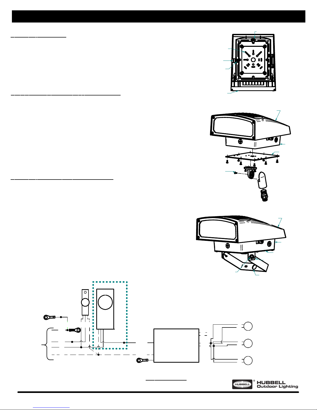
Mounting of Sling Fixture
Open the Back Box by loosening the Locking Screw.
1.
Verify and remove only necessary Gasket material where Back Box will mount.
2.
Knock-out Back Box material for necessary mounting location.
3.
Mount Back Box to Junction Box securely, using hardware supplied by others.
4.
Connect electrical connections with fixture wiring.
5.
Seal Back Box to Housing by pushing on front of Housing while tightening Locking
6.
Screw to ensure that screw is fully seated in the Housing Recess. Ensure wiring
remains within Back Box and wires do not get pinched.
Apply Caulk or other Sealant (supplied by others) around the top and both sides of
7.
the Back Box where it meets the mounting surface.
Mounting of Sling Fixture with Knuckle Accessory
Open the Back Box by loosening the Locking Screw.
1.
Mount Knuckle Plate to mounting locations of Back Box using #8-32x5/16" screws.
2.
Route electrical leads from Back Box through Knuckle Plate and Knuckle. In order to
3.
complete routing through Knuckle, may need to use Phillips head screwdriver to
remove screw at middle of the Knuckle. Make sure to reconnect Knuckle parts once
wire routing is complete.
Connect electrical connections with fixture wiring routed through the Knuckle.
4.
Mount Knuckle on desired mounting location, using sealing compound to seal
5.
Knuckle threads on mounting location.
Seal Back Box to Housing by pushing on front of Housing while tightening Locking
6.
Screw to ensure that screw is fully seated in the Housing Recess. Ensure wiring
remains within Back Box and wires do not get pinched.
If light output angle needs to be adjusted, loosen screw on middle of the Knuckle to
7.
allow rotation of Knuckle for fixture to desired light output angle. Tighten screw once
desired light output angle is achieved.
Mounting of Sling Fixture with Yoke Accessory
Open the Back Box by loosening the Locking Screw.
1.
Mount Yoke Plate to mounting locations of Back Box using #8-32x5/16" Screws.
2.
Connect Strain Relief through Back Box and Yoke Plate. Ensure gasket covers hole
3.
in Back Box.
Route SO Cord through Strain Relief into the Back Box. Twist Strain Relief to tightly
4.
secure SO Cord.
Connect SO Cord connections with fixture wiring inside the Back Box.
5.
Seal Back Box to Housing by pushing on front of Housing while tightening Locking
6.
Screw to ensure that screw is fully seated in the Housing Recess. Ensure wiring
remains within Back Box and wires do not get pinched.
Make electrical connections with SO Cord, ensuring SO cord is routed through
7.
Wireway Hole on Yoke.
Mount Yoke on desired mounting location, ensuring SO cord with electrical power
8.
connections is contained inside mounting surface (Junction Box for example). Be sure
to allow for some excess SO Cord outside mounting surface in order to rotate fixture
into desired location.
If light output angle needs to be adjusted, loosen screw on Yoke Mounting Bracket
9.
to allow rotation of Yoke for fixture to desired light output angle. Tighten screw once
desired light output angle is achieved.
PHOTOCELL
SURGE
OPTIONAL FEATURE.
USE CAP TO DEACTIVATE.
Knuckle Screw to Allow Rotation
Back Box with Gasket
Locking Screw
Housing Recess
Housing
Yoke Screw to Allow Rotation
Photocell (Use Cap to Deactivate)
Housing
Back Box
Knuckle Plate
Housing
Back Box
Yoke Plate
Yoke Mounting Bracket
Wireway Hole
GROUND TO
BUILDING
CONNECTION
BACK BOX
GROUND
GROUND TO
HOUSING COVER
GROUND
LINE
NEUT
BLACK
GREEN
WHITE
GREEN
RED
BLACK
WHITE
NOTES:
For replacement LEDs and Drivers, please contact Hubbell Lighting for any replacement parts.
Contact your local distributor or agent to confirm parts availability prior to ordering replacement parts.
701 Millennium Boulevard Greenville, SC 29607 (864) 678-1000
- INPUT -
CHECK DRIVER
CHECK DRIVER
GROUND TO
HOUSING COVER
IF PRESENT
LINE
NEUT
GND
WIRING DIAGRAM
AC LED DRIVER
-OUTPUT -
DIM +
DIM -
LED +
LED -
VIOLET
GRAY
SEE TABLE
SEE TABLE
RED
BLACK
BLACK
BLACK
LED COB
RED
LED COB
RED
LED COB
www.hubbelloutdoor.com
Page 3

INSTRUCTIONS D'INSTALLATION - SLING SHEET 1 OF 2
SAUF CES INSTRUCTIONS
INSTRUCTIONS
D'INSTALLATION
LIRE ATTENTIVEMENT AVANT L'INSTALLATION
AVERTISSEMENT!
locaux. Ne pas le faire peut augmenter le risque de blessure, DOMMAGE D'INCENDIE ET MORT. Installez et utilisez donc les échecs de
fixation ne causent pas un danger et utilisent uniquement dans des environnements pour lesquels le produit est spécifiquement marquée.
AVERTISSEMENT!
congénitales et / ou d'autres troubles de la reproduction. Se laver les mains après l'installation, la manutention, le nettoyage, ou autrement
toucher ce produit.
ATTENTION
avertissements concernant le fonctionnement du luminaire et la position de gravure. Étiquette Luminaire montre exigences et restrictions
électriques et environnementales .
Tous les travaux électriques doivent être effectués par un électricien qualifié .
Coupez l'alimentation électrique à tous les circuits touchés et laisser refroidir avant l'entretien.
Un programme d'entretien régulier devrait être établi pour conserver une sortie de lumière optimale et réduire la rétention de chaleur.
Épousseter avec un chiffon doux , propre et sec est normalement suffisant pour le système optique. Toute accumulation de poussière ou de la
saleté doit être retirée régulièrement.
Lisez attentivement ces instructions avant d'installer le produit . Si vous ne comprenez pas ces instructions, avant de commencer tout travail,
contactez votre distributeur d'éclairage Hubbell ou techsupport@hubbell-ltg.com ou (864) 678-1000
Donner des instructions aux propriétaire de l'installation / gestionnaire pour référence future.
Outils nécessaires:
Tournevis à tête plate
-
T-20 Torx
-
Tous les autres outils nécessaires pour Fixations murales appropriées
-
Les luminaires doivent être mis à la terre et installés conformément au Code national de l'électricité et tous les codes
Ce produit contient des produits chimiques reconnus par l'État de Californie pour causer le cancer, des malformations
! Suivez toutes les recommandations de luminaires , les marques de produits, des instructions, des restrictions et des
PILÈCES NÉCESSAIRES:
- MASTIC AU SILICONE
- 1/4" ANCRAGES MURAUX ET LES FIXATIONS APPROPRIÉESE POUR LE TYPE
DECONSTRUCTION MURALE
Coupez l'alimentation de connexions électriques.
••••
Le câblage doit être effectué par un électricien qualifié.
••••
Effectuer les connexions électriques selon les codes électriques locaux et nationaux.
••••
Il ya trois fils sortant de cet accessoire:
file noir - tension de la ligne
fil blanc - neutre
fil vert - fil de terre
Connectez ces fils aux fils d'alimentation en utilisant les écrous fournis dans le sac de quincaillerie.
93081542 Rev. B
701 Millennium Boulevard Greenville, SC 29607 (864) 678-1000
www.hubbelloutdoor.com
Page 4

INSTRUCTIONS D'INSTALLATION - SLING SHEET 2 OF 2
Montage du Luminaire Sling
Ouvrir la boîte arrière en desserrant la vis de blocage.
1.
Vérifiez et enlever seulement le matériel nécessaire de joint où la boîte arrière montera.
2.
Enlever le matériel de la boîte arrière pour le lieu de montage nécessaire.
3.
Monter la boîte arrière à la boîte de jonction.
4.
Branchez les connexions électriques avec le câblage de l 'appareil.
5.
Sceller la boîte arrière au boîtier en poussant sur le devant du boîtier tout en serrant la vis
6.
SAUF CES INSTRUCTIONS
Boîte arrière avec joint
de blocage pour s'assurer que la vis est bien insérée dans le logement du boîtier.
Assurez-vous que le câblage reste dans la boîte arrière et que les câbles ne sont pas pincés.
Montez le luminaire à l'aide d'un accessoire à articulation
Ouvrir la boîte arrière en desserrant la vis de blocage.
1.
Montez la plaque à articulation aux emplacements de montage de la boîte arrière en utilisant
2.
les vis #8-32x5/16" fournies.
Acheminez les fils électriques de la boîte arrière à travers la plaque à articulation et les
3.
articulation. Afin de terminer l'acheminement à travers les articulations, peut-être besoin d'utiliser
un tournevis pour enlever la vis au milieu de l'articulation. Assurez-vous de reconnecter les
pièces des chevilles une fois que le cheminement des fils est terminé.
Branchez les connexions électriques avec le câblage de l 'appareil traversant la articulation.
4.
Montez l'articulation à l'emplacement de montage souhaité, en utilisant un joint d'étanchéité
5.
pour sceller les filets sur le lieu de montage.
Sceller la boîte arrière au boîtier en poussant sur le devant du boîtier tout en serrant la vis de
6.
blocage pour s'assurer que la vis est bien insérée dans le logement du boîtier. Assurez-vous que
le câblage reste dans la boîte arrière et que les câbles ne sont pas pincés.
Si l'angle de sortie de la lumière doit être réglé, desserrez la vis au milieu de articulation pour
7.
permettre la rotation de articulation du luminaire à l'angle de sortie de lumière souhaité. Serrer la
vis une fois que l'angle de sortie de la lumière souhaitée est atteint.
Montez le luminaire à l'aide d'un accessoire à joug
Ouvrir la boîte arrière en desserrant la vis de blocage.
1.
Montez la plaque à joug aux emplacements de montage de la boîte arrière en
2.
Vis articulée pour permettre la rotation
utilisant les vis #8-32x5/16" fournies
Relier le dispositif de décharge de traction. Assurez-vous que le joint recouvre le
3.
trou dans la boîte arrière.
Passez le cordon SO à travers le dispositif de décharge de traction dans la boîte
4.
arrière. Torsadez décharge de traction pour bien fixer le cordon SO.
Raccorder les connexions du cordon SO avec le câblage du luminaire dans la boîte
5.
arrière.
Sceller la boîte arrière au boîtier en poussant sur le devant du boîtier tout en serrant
6.
la vis de blocage pour s'assurer que la vis est bien insérée dans le logement du boîtier.
Assurez-vous que le câblage reste dans la boîte arrière et que les câbles ne sont pas
pincés.
Effectuer les connexions électriques avec le cordon SO, en veillant à ce que le
7.
cordon SO électrique soit acheminé par le trou fil métallique.
Montez à l'emplacement de montage désiré, en veillant à ce que le cordon
8.
d'alimentation avec les connexions d'alimentation électrique soit contenu à l'intérieur
de la surface de montage (boîte de jonction par exemple). Assurez-vous de laisser un
peu d'excédent de cordon d'alimentation à l'extérieur de la surface de montage afin de
faire pivoter le luminaire dans l'emplacement désiré.
Si l'angle de sortie de lumière doit être réglé, desserrez la vis sur le support de
9.
montage pour permettre la rotation du luminaire à l'angle de sortie de lumière souhaité.
Serrer la vis une fois que l'angle de sortie de la lumière souhaitée est atteint.
PROTECTEUR
DE SURTENSION
PHOTOCELLULE
Photocellule
(Utiliser le cap pour désactiver)
Vis de blocage
Logement du Boîtier
Boîtier
Vis pour permettre la rotation
Boîtier
Boîte arrière
Plaque à articulation
Boîtier
Boîte arrière
Plaque à joug
Support de montage
Trou fil métallique
TERRAIN AU
CONNECTER
LE LUMINAIRE
AU FILAGE EXTERNE
ARRIÈRE BOÎTE
GROUND
TERRAIN AU
LOGEMENT
TERRE
LIGNE
NEUT
VERT
NOTES:
Pour le remplacement des LED et les pilotes , s'il vous plaît contactez- Hubbell Lighting pour toutes les pièces de
rechange. Contactez votre distributeur ou un agent local pour confirmer la disponibilité des pièces avant de
commander des pièces de rechange.
701 Millennium Boulevard Greenville, SC 29607 (864) 678-1000
CARACTÉRISTIQUES
OPTIONNELLES.
UTILISER LE CAP
POUR DÉSACTIVER.
NOIR
BLANC
VERT
ROUGE
NOIR
BLANC
VÉRIFIER LE
CONVERTISSEUR
VÉRIFIER LE
CONVERTISSEUR
TERRAIN AU
LOGEMENT
SI PRÉSENT
- ENTRÉE C.A. -
LINE
CONVERTISSEUR
NEUT
GND
SONDES DE
TAMISAGE
- SORTIE C.C. -
LED +
LED -
VIOLET
GRIS
VÉRIFIER LE
CONVERTISSEUR
VÉRIFIER LE
CONVERTISSEUR
ROUGE
NOIR
ROUGE
NOIR
ROUGE
NOIR
LED COB
LED COB
LED COB
DIAGRAMME DE CÂBLAGE
www.hubbelloutdoor.com
 Loading...