

INSTALLATION INSTRUCTIONS - RFL4 & RFL5 LED FLOOD SHEET 1 OF 2
SAVE THESE INSTRUCTIONS
READ THOROUGHLY BEFORE INSTALLATION
WARNING!
the
environments for which the product is specifically marked.
WARNING!
wash hands after installing, handling, cleaning, or otherwise touching this product.
WARNING!
replacing light engine or otherwise servicing luminares. Disregarding this warning could result in electrical shock and possible injury to the individual
installing or servicing this equipment. Installation and servicing should be done by qualified personnel.
CAUTION!
position. Luminaire label shows electrical and environmental requirements and restrictions.
NOTE!
All electrical work must be done by a qualified electrician.
Turn off electric power to all affected circuits and allow to cool before installation or servicing.
A regularly scheduled maintenance program should be established to retain optimum light output and reduce heat retention. Dusting with a soft, clean,
dry cloth is normally sufficient for the optical system. Any accumulation of dust or dirt should be removed regularly.
Carefully read these instructions before installing product. If you do not understand these instructions, before starting any work, contact your Hubbell
Lighting distributor or techsupport@hubbell-ltg.com or (864) 678-1000
Give instructions to facility owner/manager for future reference.
Mounting The Fixture
Tools Required:
3/4" or 3/8" Wrench or Socket (Trunnion Mount)
3/8" Hex Key
Fixtures must be grounded and installed in accordance with the National Electrical Code and all local codes. Failure to do so may increase
RISK OF PERSONAL INJURY, PROPERTY DAMAGE, FIRE AND DEATH.
This product contains chemicals known to the State of California to cause cancer, birth defects, and/or other reproductive harm. Thoroughly
Dangerous voltage exist within the unit and all precautions usually observed in handling high voltage equipment should be observed when
Follow ALL luminaire recommendations, product markings, instructions, restrictions and warnings regarding luminaire operation and burning
This luminare is designed for outdoor lighting applications with ambient temperatures not exceeding 40°C (104°F).
Install and use so fixture failures do not cause a hazard and use only in
Turn off power to electrical connections.
•
Wiring must be performed by a qualified electrician.
•
Make electrical connections according to the local and National Electrical Codes.
•
Remove fixture from packaging along with hardware bag.
•
There are three wires coming out of this fixture:
•
Black Wire - Line Voltage
White Wire - Neutral
Green Wire - Ground
Connect these wires to the supply wires using the wire nuts provided in the hardware bag.
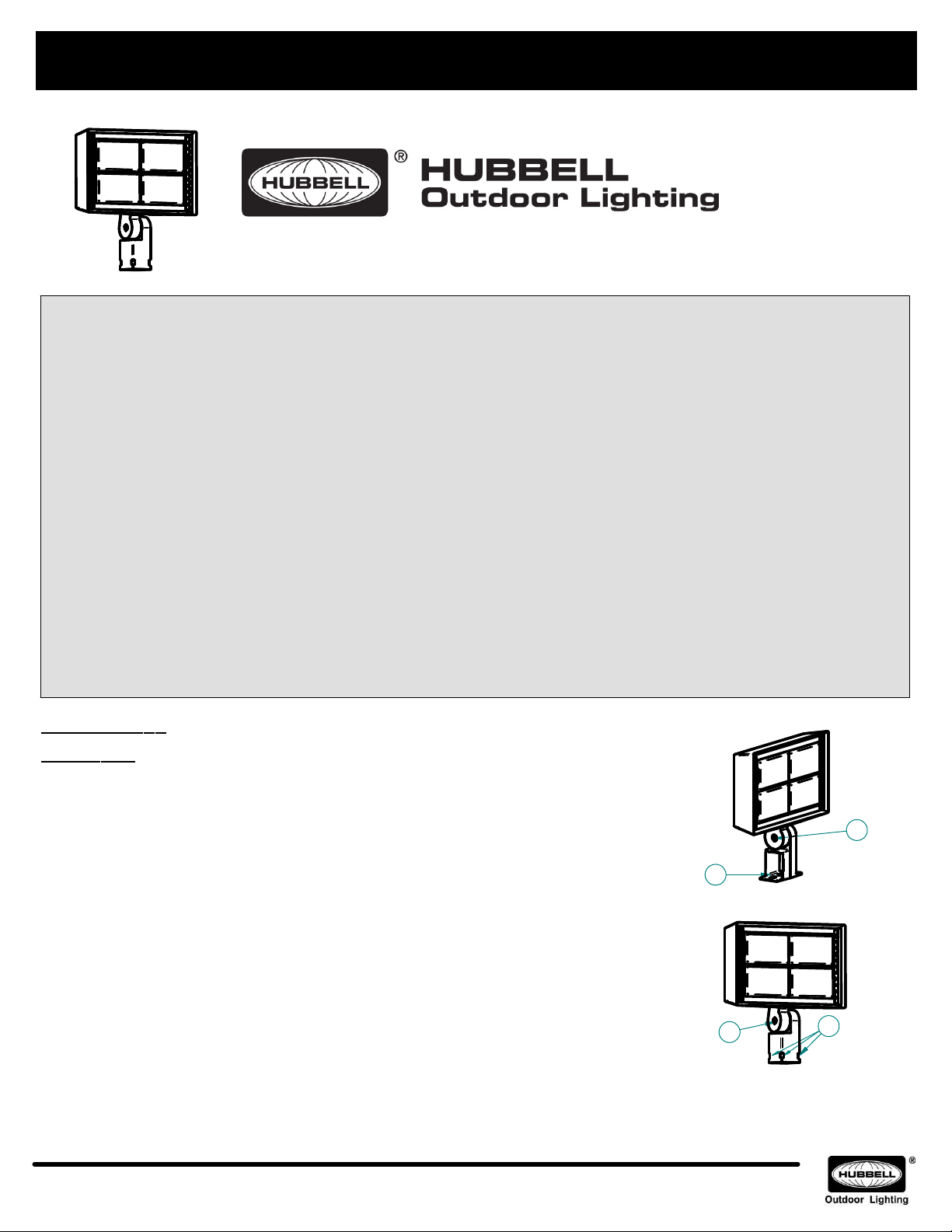
Trunnion Mount
Use a minimum of two 3/8" diameter bolts or one 3/4" diameter bolt for mounting (Item 1 in Fig. 1).
•
Loosen the bolt (Item 2 in Fig. 1) on the knuckle using a 3/8" hex key to allow the fixture to be aimed up or down.
•
Once the fixture is aimed at the desired target, tighten the bolt (Item 3 in Fig. 1) on the knuckle.
•
Knuckle Mount
Mount fixture on 2 3/8" tenon, tighten down 4 set screws (Item 3 Fig. 2).
•
Loosen bolt inside knuckle enough to adjust fixture.
•
(Item 4 Fig. 2).
(Fig. 1):
(Fig. 2):
Once fixture is aimed at the desired target, tighten the bolt
93101891 Rev. A
Hubbell Lighting • 701 Millennium Boulevard • Greenville, SC 29607 • Phone: 864-678-1000
Due to our continued efforts to improve our products, product specifications are subject to change without notice.
© 2016 Hubbell Lighting, All Rights Reserved • For more information visit our website: www.hubbelloutdoor.com
2
1
FIGURE 1
4
FIGURE 2
3
INSTALLATION INSTRUCTIONS - RFL4 & RFL5 LED FLOOD SHEET 2 OF 2
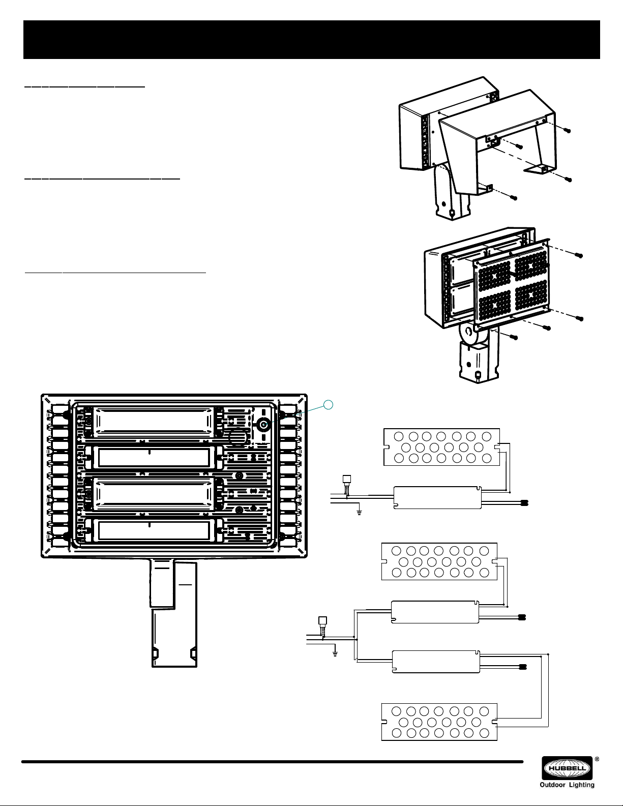
Mounting The Visor (See Fig. 3)
SAVE THESE INSTRUCTIONS
Turn off power to electrical connections.
•
Remove Visor from packaging along with hardware bag.
•
Drill four holes using a #24 (0.152" diameter) drill bit, 1/2" depth, at the
•
locations shown (Fig. 3). A small recess is provided on the housing for each
drilled hole. No tapping of the holes will be necessary after drilling.
Mount the visor using the #8-32 x 3/8" thread-forming screws supplied with
•
the Visor. Tighten the screws until Visor is secure.
Mounting the Louver System (See Fig. 4)
Turn off power to electrical connections.
•
Remove Louver System from packaging along with hardware bag.
•
Place Louver System over lenses and drill 6 holes using a #24 (0.152"
•
diameter) drill bit, 1/2" depth,through the mounting holes (Fig. 4). No tapping
of the holes will be necessary after drilling.
Mount the Louver System using the #8-32 x 3/8" thread-forming screws
•
supplied. Tighten the screws until the Louver System is secure.
Installing the Photocontrol (See Fig. 4, 5, and 6)
Turn off power to electrical connections.
•
Wiring must be performed by a qualified electrician.
•
Remove Photocontrol from packaging along with hardware bag.
•
Remove the four screws on the rear of the flood light.
•
Remove the front plate and drill an 11/16" (0.6875") diameter hole on the location provided
•
(Item 1, Fig 5).
Mount the Photocontrol in the drilled hole.
•
Connect the Photocontrol as shown in Fig.6 for RFL4 or Fig 7 for RFL5.
•
Reinstall the front plate with light engine and tighten the screws that were removed.
•
FIGURE 3
FIGURE 4
1
PHOTOCONTROL
OPTION
LINE
BLACK
RED
BLACK (LINE)
WHITE(NEUT)
BLACK (LINE)
WHITE(NEUT)
BLACK (LINE)
WHITE(NEUT)
AC INPUT
AC INPUT
AC INPUT
GREEN
GRD
LINE
COM
GROUND
PHOTOCONTROL
OPTION
BLACK
RED
GROUND
GREEN
COM
GRD
FIGURE 5
NOTES:
For replacement LED Assemblies and Drivers please
contact Hubbell Lighting.
Contact your local distributor or agent to confirm parts
availability prior to ordering replacement parts.
93101891 Rev. A
Hubbell Lighting • 701 Millennium Boulevard • Greenville, SC 29607 • Phone: 864-678-1000
Due to our continued efforts to improve our products, product specifications are subject to change without notice.
© 2016 Hubbell Lighting, All Rights Reserved • For more information visit our website: www.hubbelloutdoor.com
LED BOARD
DRIVER
Fig 6: Wiring Diagram for RFL4 Flood
DC OUTPUT
LED BOARD
DRIVER
DRIVER
DC OUTPUT
DC OUTPUT
LED BOARD
Fig 7: Wiring Diagram for RFL5 Flood
DIMMING
LEADS
DIMMING
LEADS
DIMMING
LEADS
RED(+)
BLACK(-)
RED(+)
BLACK(-)
RED(+)
BLACK(-)
RED
PURPLE(+)
GREY(-)
RED
PURPLE(+)
GREY(-)
PURPLE(+)
GREY(-)
BLACK(-)
RED(+)
BLACK
BLACK
 Loading...