

Page 1
INSTALLATION and MAINTENANCE INSTRUCTIONS
TMR SERIES ELECTRIC CABLE REELS
DESCRIPTION
The TMR series reel is designed to automatically lift and
retrieve electric cable. The reel incorporates a rotating hollow
shaft with spool mounted outboard on one end and collector
assembly on the opposite end. The main shaft, rotating on
two flange block bearings, is driven by an electric torque motor
through a chain drive. The torque motor has an electronically
released break holding the spool stationary when the reel is
not in use.
INSTALLATION
1. Thoroughly inspect reel upon receipt for damage that may
have been caused in shipping.
2. Mount reel with the main shaft horizontal and level and
with the spool centerline in line with the cable tray. Mount
at recommended height so that proper distance from the
center of the spool to the cable tray is maintained.
CAUTION
Exceeding designed lift distance may lead
to poor cable spooling and
erratic operation because the electric motor
will have insufficient torque.
3. Remove collector cover. Connect conduit to line entrance
of collector housing and connect wires to brushes of
collector assembly. Brush terminals are number coded.
Be careful that incoming wires do not put strain on brush
terminals and cause brush misalignment. Replace
collector cover.
4. Connect motor to electric line of proper specification as
stamped on motor nameplate. Refer to wiring diagram
(below, in terminal box or on name plates. 3-lead
polyphase and 2-lead single phase do not require
diagram). Provide suitable overload protection based on
full load ampere rating shown on nameplate as
recommended by control manufacturer. Protect wiring circuit
with proper fuses selected according to local codes.
OPERA TION
The reel is activated when power is supplied to the torque
motor through the main starting control of the equipment.
Care should be taken to see that all electrical connections are
made before power is turned on to the collector ring and
torque motor. All nuts and bolts should be checked to see that
they are tight. Check to make sure collector ring brushes are
aligned on rings.
MAINTENANCE
GENERAL LUBRICATION: All bearings provided with grease
fittings are lubricated at the factory before shipment. They
should be regreased periodically depending on the running
time of the reel, more often if used in dusty conditions. Parts
with bearing assemblies not provided with grease fittings are
equipped with sealed bearings and do not require lubrication.
CHAIN CASE: Every three months, remove cover from chain
case, check chain tension, and lubricate chain using a lithium
based heavy duty chain lubricant.
TORQUE MOTOR GEAR REDUCER: See section 5.2.2 of
the enclosed brake motor operation instructions for grease
lubrication. This gear reducer is filled with grease when used
with 600 RPM torque motor.
TORQUE MOTOR: Reel is equipped with a Demag torque
motor. See enclosed brake motor operation instructions.
INSPECTION: Every six months inspect entire reel to see that
all nuts, bolt, screws, and set screws are in place and tight and
that no parts show undue wear. Yearly (more often depending
on duty cycle), check brushes on collector rings. Replace
brushes when worn to the shunt
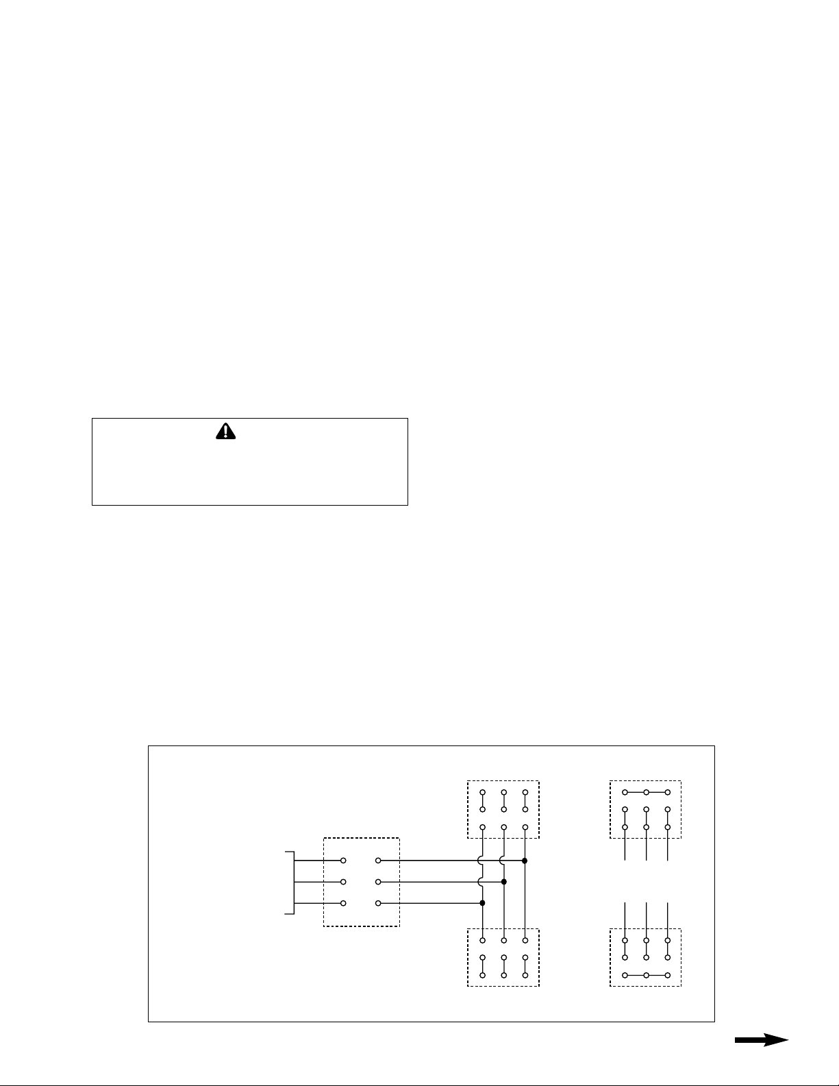
WIRING DIAGRAM
REEL MOTOR
CONTROL PANEL
(Supplied by customer
L3
SUPPLY VOLTAGE
230V or 460V
3 PHASE 60Hz
NOTE: Reel start/stop circuit should be wired into main machine
power master switch (not to machine travel drive motors). Frequent
starting and stopping of torque motor is not recommended.
Torque motor should be wired to wind cable only. Torque motor
compensates for direction change when cable is unwound.
NOTE: Be sure blower motor is also wired up with motor.
T3
L2
T2
L1
T1
TORQUE MOTOR
3/60Hz/460V
456
789
123
T3
T2
T1
123
789
456
BLOWER
3/60Hz/460V
TORQUE MOTOR
3/60Hz/230V
456
789
123
123
789
456
BLOWER
3/60Hz/230V
CONTINUED ON BACK PAGE
Page 2

ILLUSTRATED PARTS LIST
TMR SERIES ELECTRIC CABLE REELS
11
Cable is played out and retracted as shown
when viewing reel from motor side.
19
12
12
TO DETERMINE ROTATION OF REEL
STANDARD ROTATION REVERSE ROTATION
2
7
3
1
8
9
7
8
10
4
12
13
Always specify SERIAL NUMBER &
MODEL NUMBER when ordering parts.
4
16
5
6
14
18
15
17
Page 3

TMR SERIES ELECTRIC CABLE REEL REPLACEMENT PARTS LIST
NOTE: Applicable mounting hardware included with each kit.
ITEM KIT NO. DESCRIPTION QTY.
1 021372 Frame Assembly-TMR 1
2 020784 Collector Shaft 1
3 021752 Bearing Kit–2" bore 1
(Includes housing and gasket)
4 012402 Bearing Kit–2" Bore 1
(Includes housing and gasket)
5 105060 Retaining Ring 1
6 021407 Torque Motor-2 1
6 021408 Torque Motor-3 1
6 021409 Torque Motor-5 1
6 021410 Torque Motor-7 1
6 021411 Torque Motor-10 1
6 021412 Torque Motor-14 1
7 021771 Sprocket Kit, Ratio AA 1
(Includes two sprockets and keys)
7 021772 Sprocket Kit, Ratio AB 1
7 021773 Sprocket Kit, Ratio AC 1
7 021774 Sprocket Kit, Ratio AD 1
7 021775 Sprocket Kit, Ratio AE 1
8 021759 Idler Kit 1
(Includes sprocket, shaft, tensioner bar,
locking collar and mounting hardware)
9 021760 Roller Chain Kit 1
(Includes connecting link)
10 021006 Reinforcing Plate 1
11 012459 Cable Connector–.38 to .50 Dia. Cable 1
11 012460 Cable Connector–.50 to .62 Dia. Cable 1
11 012461 Cable Connector–.62 to .75 Dia. Cable 1
11 012462 Cable Connector–.75 to .88 Dia. Cable 1
11 012463 Cable Connector–.88 to 1.00 Dia. Cable 1
11 012464 Cable Connector–1.00 to 1.12 Dia. Cable 1
11 012465 Cable Connector–1.12 to 1.25 Dia. Cable 1
11 012466 Cable Connector–1.25 to 1.38 Dia. Cable 1
11 012467 Cable Connector–1.38 to 1.50 Dia. Cable 1
11 021764 Cable Connector–1.50 to 1.62 Dia. Cable 1
11 021765 Cable Connector–1.62 to 1.75 Dia. Cable 1
12 021763 Chain Cover Kit 1
(Includes cover, gasket and hardware)
13 016337 Collector Entrance Assembly 1
ITEM KIT NO. DESCRIPTION QTY.
14 101652 Pipe Plug 1
15 012285 Collector Assembly, 2 Pole, 35 Amp 1
15 012286 Collector Assembly, 3 Pole, 35 Amp 1
15 012287 Collector Assembly, 4 Pole, 35 Amp 1
15 012288 Collector Assembly, 6 Pole, 35 Amp 1
15 012289 Collector Assembly, 8 Pole, 35 Amp 1
15 012290 Collector Assembly, 10 Pole, 35 Amp 1
15 012291 Collector Assembly, 12 Pole, 35 Amp 1
15 012292 Collector Assembly, 14 Pole, 35 Amp 1
15 012293 Collector Assembly, 16 Pole, 35 Amp 1
15 012294 Collector Assembly, 20 Pole, 35 Amp 1
15 012295 Collector Assembly, 24 Pole, 35 Amp 1
15 012296 Collector Assembly, 30 Pole, 35 Amp 1
15 012297 Collector Assembly, 36 Pole, 35 Amp 1
15 012298 Collector Assembly, 2 Pole, 75 Amp 1
15 012299 Collector Assembly, 3 Pole, 75 Amp 1
15 012300 Collector Assembly, 4 Pole, 75 Amp 1
15 012376 Collector Assembly, 6 Pole, 75 Amp 1
15 012377 Collector Assembly, 8 Pole, 75 Amp 1
15 037194 Collector Assembly, 2 Pole, 125 Amp 1
15 037294 Collector Assembly, 3 Pole, 125 Amp 1
15 037295 Collector Assembly, 4 Pole, 125 Amp 1
15 012304 Collector Assembly, 2 Pole, 200 Amp 1
15 012381 Collector Assembly, 3 Pole, 200 Amp 1
15 012382 Collector Assembly, 4 Pole, 200 Amp 1
15 012383 Collector Assembly, 6 Pole, 200 Amp 1
15 012384 Collector Assembly, 8 Pole, 200 Amp 1
16 012440 Brush Kit (35 Amp) ar
16 012441 Brush Kit (75 Amp) ar
16 012443 Brush Kit (125 Amp/200 Amp) ar
17 012409 Collector Cover Kit (8" long) 1
17 012410 Collector Cover Kit (10.5" long) 1
17 012411 Collector Cover Kit (13" long)
17 012412 Collector Cover Kit (15.5" long) 1
17 012413 Collector Cover Kit (20.5" long) 1
17 012414 Collector Cover Kit (28.5" long) 1
18 012458 Seal Ring (only) 1
19
*
Consult factory for part number of Spool Assembly and related hardware.
Please give model number and serial number to obtain correct Spool Assembly.
(Each kit includes 4 brushes and 4 fingers)
(Includes seal ring)
* Spool Assembly 1
MODEL NUMBER EXPLANATION
(Typical model number)
TMR - 4 12 - XX XX XX - AE - 3
REEL
TYPE
NUMBER
POLES
AMPACITY
CODE*
SPOOL
DIMENSIONS
and TYPE
CHAIN
RATIO
CODE**
MOTOR
SIZE
*SLIP RING
AMPACITY CODE
MAX
CODE AMPS
335
775
12 125
20 200
**CHAIN RATIO
CODE
CHAIN
CODE RATIO
AE 1.0:1
AD 1.5:1
AC 2.0:1
AB 2.5:1
AA 3.0:1
Page 4
CABLE REMOVAL
Use the following procedure to remove worn or damaged cable
from reel prior to installation of new cable.
1. Move machine serviced by reel to a position closest to
reel.
2. Turn off all electric power.
3. Lock spool to prevent turning using either a spool lock
mechanism or by tying off.
4. Disconnect cable from machine junction box.
5. Remove cable from spool. Loosen cable connector (Item 11
on parts list) and disconnect conductors from slip ring.
6. Install new cable following instruction below.
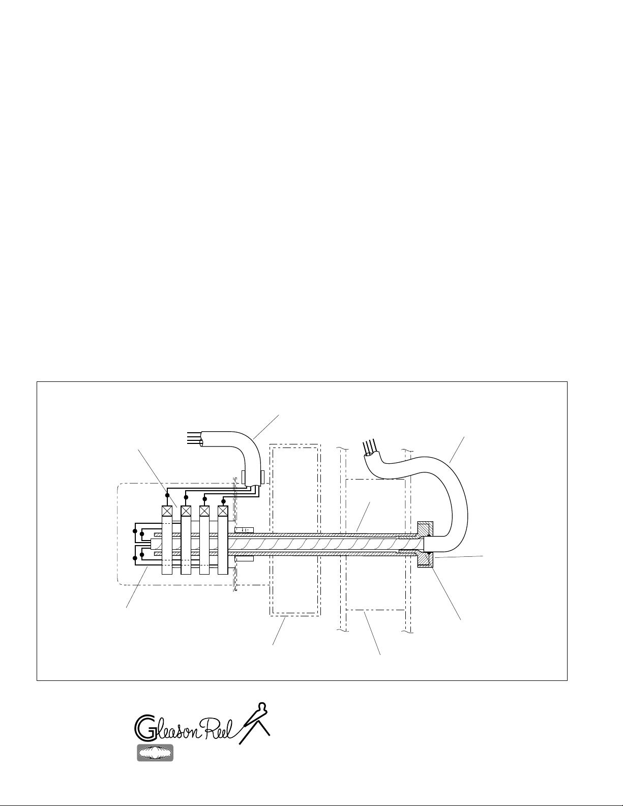
CABLE INSTALLATION
Use the following procedure to replace cable or if reel was
ordered without cable. Refer to CABLE INSTALLATION
REFERENCE DRAWING, below.
1. Unspool new cable from shipping spool and lay out
to eliminate twist.
NOTE: This step is not essential, but will aid in winding
operation of the reel and prolong cable life.
2. Feed one end of the cable through cable connector on
the main shaft inside the spool and into the slip ring side.
(See drawing below).
NOTE: This may require that jacket of cable be stripped
to allow conductors to pass through shaft.
3. Connect individual conductors to appropriate rings on
collector using crimp fitting or similar connection method.
4. Tighten cable connector and U-bolt provided on
drum wrapper segments. Do not over-tighten.
5. Wind the cable onto the reel spool by hand rotating
spool.
6. Connect free end of cable to machine junction box.
COLLECTOR REPLACEMENT
1. Turn off all power to reel.
2. Remove collector cover and gasket.
3. Disconnect electric leads to and from collector.
4. Remove drive stud bolt from bearing housing.
5. Remove plug plug from hole in side of housing. Insert
long 1/8” Allen wrench through hole and loosen two set
screws in collector locking collar Set screws are at 90
to one another..
NOTE: Older reels may have lock screws which must be
removed to reach set screws holding collector to shaft.
6. Slide collector off shaft.
7. Install new collector by reversing above steps.
O
CABLE INSTALLATION REFERENCE DRAWING
Collector
Connect leads
to collector
Frame/Gear Case
Cable
(Input)
Reel
Shaft
Spool
Cable
(Output)
Cable Gland
Thread gland into
shaft. Thread cable
thru gland and shaft.
Tighten gland cover
to secure cable.
NOTE:
Strip cable to inside
of gland. Wrap
leads with electrical
tape thru shaft.
Printed in USA
HUBBELL
®
®
A Hubbell Company
GLEASON REEL CORP.
P.O. Box 26 • 600 South Clark St
Mayville, WI 53050–0026
Phone 920–387–4120
Fax 920–387–4189
Bulletin No. 053151.a
 Loading...