

Page 1
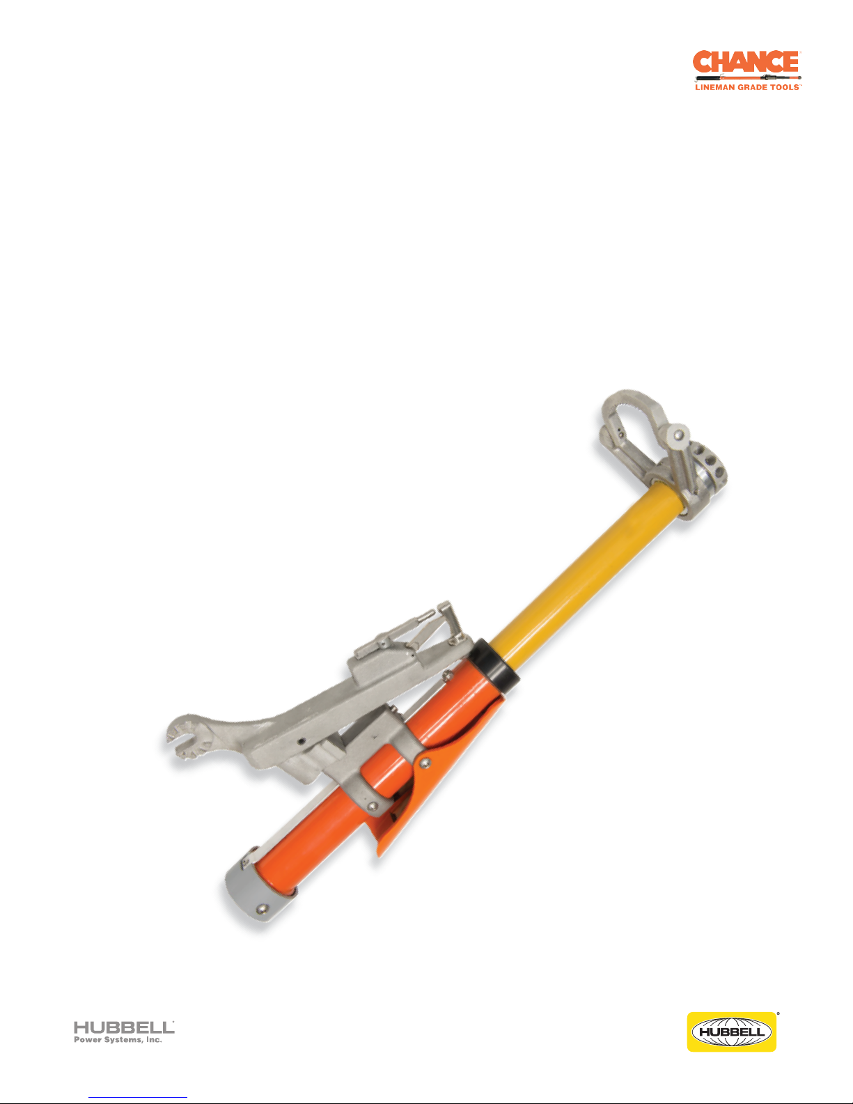
Portable Load Break Tool
Operation Manual
PSCLBT27
Hubbell has a policy of continuous product improvement. Please visit hubbellpowersystems.com to confirm current design specifications.
©2015 Hubbell Incorporated | hpsliterature@hubbell.com | hubbellpowersystems .com
Page 2

Table of Contents
Introduction
Warnings
Ratings
Application
Features
Warranty
Safety Procedures
Tool Operation
Operational Life
3
3
4
4-5
5
5
5
6-7
7
©2015 Hubbell Incorporated | Chance® Load Break Tool
2
Page 3

Introduction
The Chance® Load Break Tool was designed with feedback from the Linemen who use the product.
The Load Break tool is designed to be 24% lighter, reducing muscle strain and increasing
maneuverability of the unit. Additionally, the tool-reset trigger has been redesigned to allow for a
simple reset, even if you are wearing thick gloves.
The Chance® Load Break Tool is designed to aid in operation of disconnects, load break switches,
capacitor banks, fuse limiters, power fuses, and cutouts. Each tool is manufactured in accordance
with a quality system certified to ISO 9001: 2008.
The Chance® Load Break Tool will help cut installation and operation costs as there will be no
need for load interrupters on each device. The procedures for switching are designed to reduce
complications and to minimize the duration and scope of outages. The Chance® Load Break Tool
complies with OSHA 29 CFR Part 1910.269 (published JAN 1994) and states “Devices used to
open circuits under load Conditions shall be designed to interrupt the current involved."
Warnings
CAUTION!
The equipment covered by this instruction guide should be selected, installed and serviced by
competent personnel who understand proper safety procedures. This instruction guide is written
for such personnel and is not a substitute for adequate training and experience in safety procedures
regarding this type of equipment.
This guide does not claim to cover all details or variations in equipment nor to provide for all possible
conditions to be met with concerning installation, operation or maintenance of this equipment. If
further information is desired or if particular problems are encountered which are not sufficiently
covered in this guide, contact Hubbell Power Systems, Inc.
CAUTION
!
The Chance
applications that meet the ratings of the tool. The ratings of each tool are noted on a label attached to
the tool. If the label is missing or illegible, the tool should be taken out of service.
Follow safe work practices when using this product. Failure to use this product in a safe manner can
cause injury or death. Never use this tool in violation of your company safe work procedures.
®
Load Break Tool is designed for, and must only be used for specific switching
WARNING
!
NOTICE
This instruction sheet should be stored with the tool and readily available as a reference document
whenever the tool is used. Thoroughly read and understand these instructions completely prior to
using the product. If you do not understand any portion of this manual, contact the manufacturer
for clarification prior to using the product.
CAUTION
!
When repairing or reconditioning the Chance® Load Break Tool, only use the appropriate
components offered by the manufacturer. Failure to use appropriate components will void the
manufacturer's warranty, and may lead to product malfunction, injury or death.
©2015 Hubbell Incorporated | Chance® Load Break Tool
3
Page 4

Ratings
Chance® Load Break Tool is available in the following rating:
The
PSCLBT27
Voltage Nominal 14.4 / 25 kV - Maximum 27 kV
Amperage Nominal 600A - Maximum 900A
Application
The Chance® Load Break Tool is suitable for live-switching duties of single or three phase overhead
distribution circuits up to 27kV and underground distribution circuits up to 25 kV. It must be used with
appropriately designed equipment with “load break hooks.” Such equipment includes disconnect
switches, cutouts, power fuses, fuse limiters, and pad mounted switch gear.
•
Transformer switching - transformer load currents up to 600 amperes nominal, 900 amperes
maximum, as well as transformer magnetizing currents associated with the applicable loads.
•
Line switching - load splitting (parallel or loop switching) and load dropping of currents up to
600 amperes nominal, 900 amperes maximum; also line dropping (charging currents
for distribution systems of these voltage ratings).
•
Cable switching - load splitting (parallel or loop switching) and load dropping of currents up to
600 amperes nominal, 900 amperes maximum; also cable dropping (charging currents typical
for distribution systems of these voltage ratings).
• Capacitor bank switching - switching of single capacitor banks as follows:
typical
Maximum Capacitor Bank Rating, kVAC, Three Phase
Catalog
Number
PSCLBT27
* Tools must not be used for switching parallel (“back-to-back”) capacitor banks.
# Tools must not be used for switching ungrounded-wye connected banks or grounded-
wye connected banks on ungrounded systems where maximum system operating
voltage exceeds 18 kV for Catalog Number
Nominal System
Voltage, kV,
Three-Phase
12 thru 14.4
16
20.8 thru 23.9
24.9 and 26
Solid or Effectively Grounded System Ungrounded System
Single* Banks,
Grounded-Wye
Connected
1800
2400
3000
3600
PSCLBT27
Single* Banks,
Ungrounded-Wye
Connected
1800
2400
#
#
Single* Banks,
Grounded or
Ungrounded-Wye
Connected
1800
2400
#
#
©2015 Hubbell Incorporated | Chance® Load Break Tool
4
Page 5

Application
A Note on Single-Pole Switching
In single-pole switching of ungrounded-primary three-phase transformers or banks (or single-phase
transformers connected line-to-line), circuit connections or parameters may, in some cases, produce
excessive over voltages. In particular, for the following applications above 22 kV, single-pole
switching by any means including The Chance® Load Break Tool should be performed only under
the conditions stated in italics:
•
Switching unloaded or lightly loaded delta-connected or ungrounded-primary wye-wye connected
three-phase tr
kVA or less three-phase, or 50 kVA or less single phase or of any kVA rating when combined with
unloaded cables or lines where maximum system operating voltage exceeds 22 kV.
Single-pole switching should be performed only if each phase is carrying 5% load or more, or if the
transformer or bank is temporarily grounded at the primary neutral during switching.
•
Switching loaded or unloaded ungrounded-primary wye-delta connected three-phase
transformers or banks alone or combined with unloaded cables or lines where maximum system
operating voltage exceeds 22 kV.
Single-pole switching should be performed only if each phase is carrying 5% load or more and if
the lighting-load phase is always switched open first (or switched closed last); or if the transformer
or bank is tempor
ansformers or banks (or line-to-line connected single-phase transformers), rated 150
arily grounded at the primary neutral during switching.
Features
• Reset Paddle will not pinch fingers
• Maximum tool movement
• Full operational ratings
•
No exposed springs to pinch linemen's gloves
• Reset Paddle is easy to use with gloves
•
Operation counter
Warranty
The Chance® Load Break Tool carries a full (1) one year warranty on workmanship, parts and
labor against normal wear and tear from the original date of purchase. The tool is NOT
warranted against misuse or misapplication.
Safety Procedure
Follow all basic and necessary procedures to secure the electrical site before beginning work.
Wear proper safety equipment and follow all existing codes, requirements and instructions for all
equipment used in conjunction with the Chance® Load Break Tool. Misuse of this tool can cause
serious
Only trained and qualified personnel should operate, inspect and maintain this device. Do not use
this tool on applications where the maximum system voltage exceeds the maximum design voltage
rating of the tool. Likewise, do not use a tool that is “over-rated” for the application voltage. When
you receive your Chance® Load Break Tool familiarize yourself with all operational features prior to
use. It is also recommended that the user practice using the tool on de-energized equipment to
gain familiarity with proper operation and handling of the tool.
injury or death. Fully read and understand the instruction manual before using this product.
©2015 Hubbell Incorporated | Chance® Load Break Tool
5
Page 6

Tool Operation
1.
It is critical that the Chance® Load Break Tool be inspected both visually and mechanically prior
to operation. To perform the inspection, the following steps must be performed:
1. Check the black top ring to verify that it is fully seated and has not loosened.
2. Inspect any external moving components for full mechanical functionality.
3. To ensure proper mechanical spring operation, extend the yellow tube no more than 3
inches and verify that the spring force retracts the yellow tube to its initial closed position. If
the tool fails to retract back to the initial closed position, it will be necessary to disassemble
and properly service the tool prior to use.
4.
To perform full mechanical operation on the Chance® Load Break Tool, extend the yellow
tube until the tool locks out into the open locked position. To release from the open locked
position and retract the tool back to the closed position, press the large orange paddle on
the side of the tool. Once pressed, the yellow tube will automatically retract back to the
initial closed position. If this does not occur, disassemble and properly service the tool prior
to use.
5.
Inspect all exterior surfaces of the Chance® Load Break Tool to verify the surfaces are
clean and free of damage.
2. For optimal functionality, it is necessary to determine the best location to approach the cutout or
switch intended for operation.
• The operator should determine a standing location that allows full control of the tool
without resulting in a loss of footing during operation.
•
For optimal hand control of the Chance® Load Break Tool, the operator should always
approach the cutout or switch from below on the side of the pole with the least congestion
to minimize the chance of contact with other pole equipment.
• The operator should choose a location that allows an operation angle of 45° below
horizontal, directed straight out from the cutout or switch.
• Never choose a location that places the tool on the same side of the cutout or switch as the
operator (see Figure 1). It is necessary for the user to connect the
Tool on the opposite side of the cutout or switch from their position below (See Figure 2).
Chance® Load Break
Figure 1 - Incorrect Approach Figure 2 - Correct Approach
©2015 Hubbell Incorporated | Chance® Load Break Tool
6
Page 7

Tool Operation
3. Once a suitable location has been determined that allows the user to safely operate the Chance
Load Break Tool, it is necessary to connect the tool to the arcing horns of the cutout or switch.
1.
To connect the Chance® Load Break Tool to the cutout or switch, install the hook loop
onto the arcing horns.
2.
To connect the cutout or switch pull ring to the Chance® Load Break Tool, maneuver the
tool in an angular motion that allows the spring loaded clip assembly to engage the pull ring
and lock securely. It may be necessary to extend the Chance® Load Break
accomplish connection.
4.
Operating the cutout or switch with the Chance® Load Break Tool.
•
Firmly pull the tool downward at the 45° angle, straight out from the cutout or switch.
Once the load
disconnect the fuse electrically from the power system.
• The speed at which the user pulls the cutout or switch will not have an impact on the
functionality of the tool. The user should choose a speed of operation that allows them to
have full control over the tool at all times.
5.
Removal of the Chance® Load Break Tool from the cutout or switch.
1. Once the cutout or switch has been opened, firm contact between the hook loop and the
arcing horns should be maintained by exerting a small amount of downward pressure on the
tool.
Disengage the Chance® Load Break Tool by rotating or rolling the tool in a manner that
2.
allows the clip assembly to disengage the pull ring on the fuse.
break tool has reached the fully open position it will lockout and safely
Tool slightly to
®
3.
Move the tool slightly back toward the cutout or switch and allow the hook loop to come
off the load break ears.
6.
Preparing the tool for next operation.
• Push the hand paddle to reset the tool to the closed position.
•
Repeat steps
1 through 5 as necessary.
Operational Life
With normal usage, the Chance® Load Break Tool can be expected to reach 1,500-2,000 operations
between required inspection and maintenance. However, users should not rely solely on the counter
to determine maintenance scheduling and operational life. Tool life is not strictly dependent on
number of uses, rather it is dependent on the size of the load that is broken. Breaking a larger
electrical load will result in more tool degradation than a smaller load. The conditions in which the
tools is stored will also affect the operational life. Given the usage and storage variables 1,500-2,000
operations between inspections is only a benchmark. We recommend that each utility or contractor
establish a 6 to 12 month inspection and maintenance schedule. This will help to support the best
operational life of the equipment.
©2015 Hubbell Incorporated | Chance® Load Break Tool
7
Page 8

PSCLBT27 Chance® Load Break Tool
Voltage -
Amperage - Nominal 600A - Maximum 900A
Hook
Loop
Sping Loaded
Clip Assembly
Nominal 14.4 / 25 kV - Maximum 27 kV
Reset
Paddle
Universal
Adapter
Operation
Counter
Hubbell Power Systems, Inc.
210 N. Allen Street
Centralia, MO 65240
(573) 682-5221
www.hubbellpowersystems.com
Hubbell has a policy of continuous product improvement. Please visit hubbellpowersystems.com to confirm current design specifications.
TD_09_070_E
©2015 Hubbell Incorporated | Chance® Load Break Tool
8
 Loading...