

Page 1
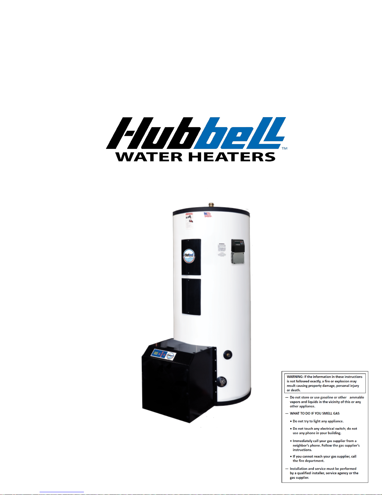
INSTALLATION, OPERATION, AND
MAINTENANCE MANUAL FOR
CONDENSING GAS
STORAGE WATER HEATER
BASE MODEL “PRIME”
Page 2

2
Table&of&Contents&
1.0 INTRODUCTION ................................................................................................................................. 4
Operating Principle ................................................................................................................................ 4
Safety Information and Precautions ...................................................................................................... 4
Outline Dimensions ............................................................................................................................... 8
Electrical .............................................................................................................................................. 10
Gas ....................................................................................................................................................... 10
2.0 INSTALLATION ...................................................................................................................................... 11
Installation Safety Notes ...................................................................................................................... 11
Installer Responsibilities .......................................................................................................... 12
Water Heater Placement ...................................................................................................................... 12
Ventilation ........................................................................................................................................... 12
Removing an Existing Water Heater from Common Venting System .................................... 13
Direct Vent Installation ........................................................................................................... 13
Combustion Air-inlet Contamination ...................................................................................... 14
Water Heater Vent/Air Piping ................................................................................................. 14
Vent and Air-inlet Pipe Length Determination ....................................................................... 15
Termination– Direct Vent Installation ..................................................................................... 16
Venting Rules and Guidelines: ................................................................................................ 20
Flammable Solvents and Plastic Piping ................................................................................... 23
Mandatory Pre-commissioning Procedure for Plastic Venting (PVC or CPVC) .................... 23
Condensate Drain ................................................................................................................................ 24
Gas Installation .................................................................................................................................... 25
Gas Valve and Burner Set-up .................................................................................................. 27
Water Piping Installation ..................................................................................................................... 30
Space Heating Application .................................................................................................................. 31
Filling the Water Heater .......................................................................................................... 32
Electrical Installation ........................................................................................................................... 32
Final Checks ........................................................................................................................................ 32
Lighting the Water Heater ................................................................................................................... 33
Initial Start-Up ......................................................................................................................... 33
Turning Off the Water Heater ................................................................................................. 34
Turning On the Water Heater .................................................................................................. 34
3.0 CONTROLLER OPERATION ................................................................................................................. 34
LCD Display ........................................................................................................................................ 34
Button Layout ...................................................................................................................................... 35
Temperature Adjustments via Status Overview .................................................................................. 36
Showing Errors on the Status Overview .............................................................................................. 37
User Menu ........................................................................................................................................... 37
Installer Menu ...................................................................................................................................... 38
Warnings .............................................................................................................................................. 39
4.0 SCHEDULED MAINTENANCE ............................................................................................................. 40
Freezing ............................................................................................................................................... 40
Manual Inspection ............................................................................................................................... 40
5.0 TROUBLESHOOTING ............................................................................................................................ 41
Controller Error Messages and Procedures ......................................................................................... 42
Lockout Codes ......................................................................................................................... 42
Blocking Errors ........................................................................................................................ 43
6.0 MAINTENANCE & SERVICING ........................................................................................................... 44
Page 3
3
Surface Temperature Hi-Limit Cutout Switch .................................................................................... 44
Removing the Condensate Outlet ........................................................................................................ 44
Removing the Fan Assembly ............................................................................................................... 44
Heat Exchanger .................................................................................................................................... 44
Relief Valve ......................................................................................................................................... 45
Heating Element (If Equipped) ............................................................................................................ 45
7.0 REPLACEMENT OF PARTS ................................................................................................................... 47
WARRANTY .................................................................................................................................................. 49
List of Figures .................................................................................................................................................. 49
List of Tables ................................................................................................................................................... 51
Page 4

1.0 INTRODUCTION
Operating Principle
The Hubbell Condensing Gas Water Heater is a Category IV water heater — a water heater that operates
with a positive vent static pressure and with a vent gas temperature that may cause excessive condensate
production in the vent. The unit uses combusted gas to transfer heat from the air to water. In comparison,
traditional electric water heaters use resistive heating elements to directly heat the water. A benefit of a gas
water heater is that gas heaters are less expensive to operate than electric resistance heaters.
This water heater utilizes the natural principles of combustion and fluid dynamics to achieve heat transfer.
Natural gas is a combustible substance, and when exposed to flames will combust. This causes the bonds
within the molecules to break, releasing the energy contained in these bonds. This energy becomes heat energy
and is how the water contained within the tank becomes hot.
After the gas has combusted, it will produce hot carbon dioxide and water vapor. These substances will
transfer heat through the stainless steel condensing unit tubing to the water contained within the tank, resulting
in hot water.
HUBBELL HEATER COMPANY
45 SEYMOUR STREET
P.O. BOX 288
STRATFORD, CT 06615
PHONE: (203) 378-2659
FAX: (203) 378-3593
INTERNET: http://www.hubbellheaters.com
-- IMPORTANT --
Always reference the full model number and serial number when calling the factory.
Safety Information and Precautions
Please read the following safety information before proceeding:
DANGER: Indicates a hazardous situation which, if not avoided, will result in serious injury or death.
WARNING: Indicates a hazardous situation which, if not avoided, could result in serious injury or death.
CAUTION: Indicates a hazardous situation which, if not avoided, could result in minor or moderate injury.
NOTICE: Indicates a hazardous situation which, if not avoided, could result in property damage.
Hazards and Definitions
Page 5
5
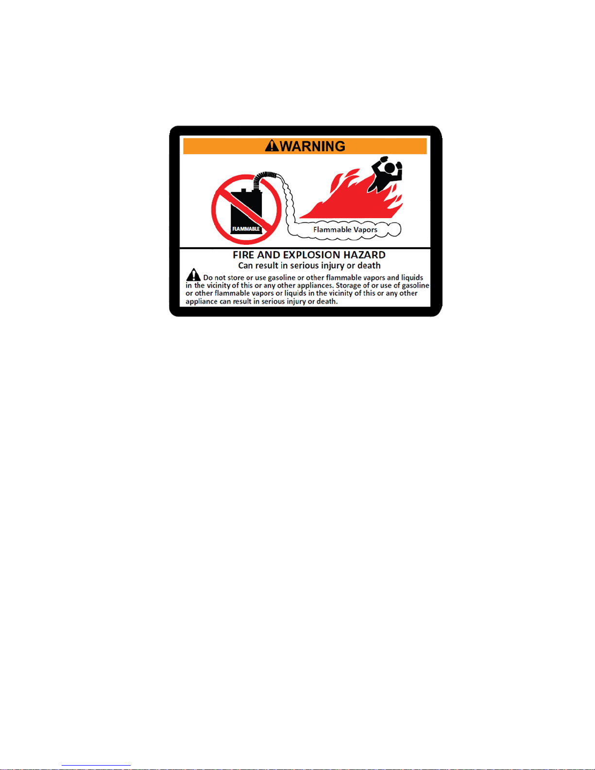
WARNING: If the information in these instructions is not followed exactly, a fire or explosion may result
causing property damage, personal injury or death.
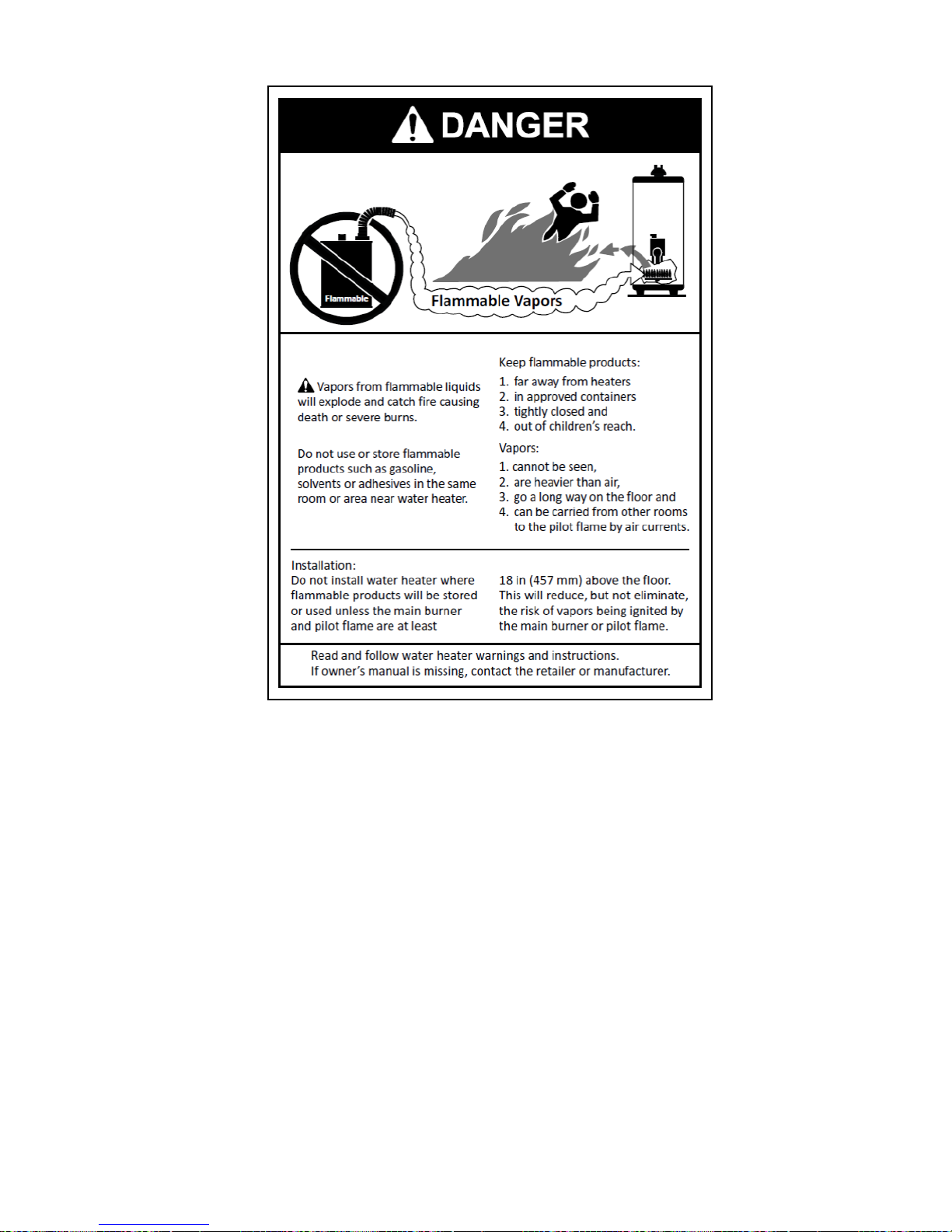
• Do not store or use gasoline or other flammable vapors and liquids in the vicinity of this or any other
appliance.
• Installation and service must be performed by a qualified installer, service agency or the gas
supplier.
• This water heater does not have a pilot. It is equipped with an ignition device which automatically
lights the burner. Do not try to light the burner by hand.
• BEFORE operating, smell around the water heater area for gas. Be sure to smell next to the floor
because some gas is heavier than air and will settle on the floor. What to do if you smell gas:
o Do not try to light any appliance.
o Do not touch any electric switch.
o Do not use any phone in your building.
o Immediately call your gas supplier from a neighbor’s phone and follow the gas supplier’s
instructions.
o If you cannot reach your gas supplier, call the fire department.
• Use only your hand to push in or turn the gas control knob. Never use tools. If the knob will not push
in or turn by hand, don’t try to repair it; call a certified service technician. Force or attempted repair
may result in a fire or explosion.
• Do not use this water heater if any part has been under water. Immediately call a qualified service
technician to inspect the water heater and to replace any part of the control system and any gas
control which has been underwater.
WARNING: Void Warranty - This Water heater must be filled with water whenever the burner is on or it
will damage the unit and void the warranty. Failure to follow these instructions may result in serious injury
or death.
Page 6
6
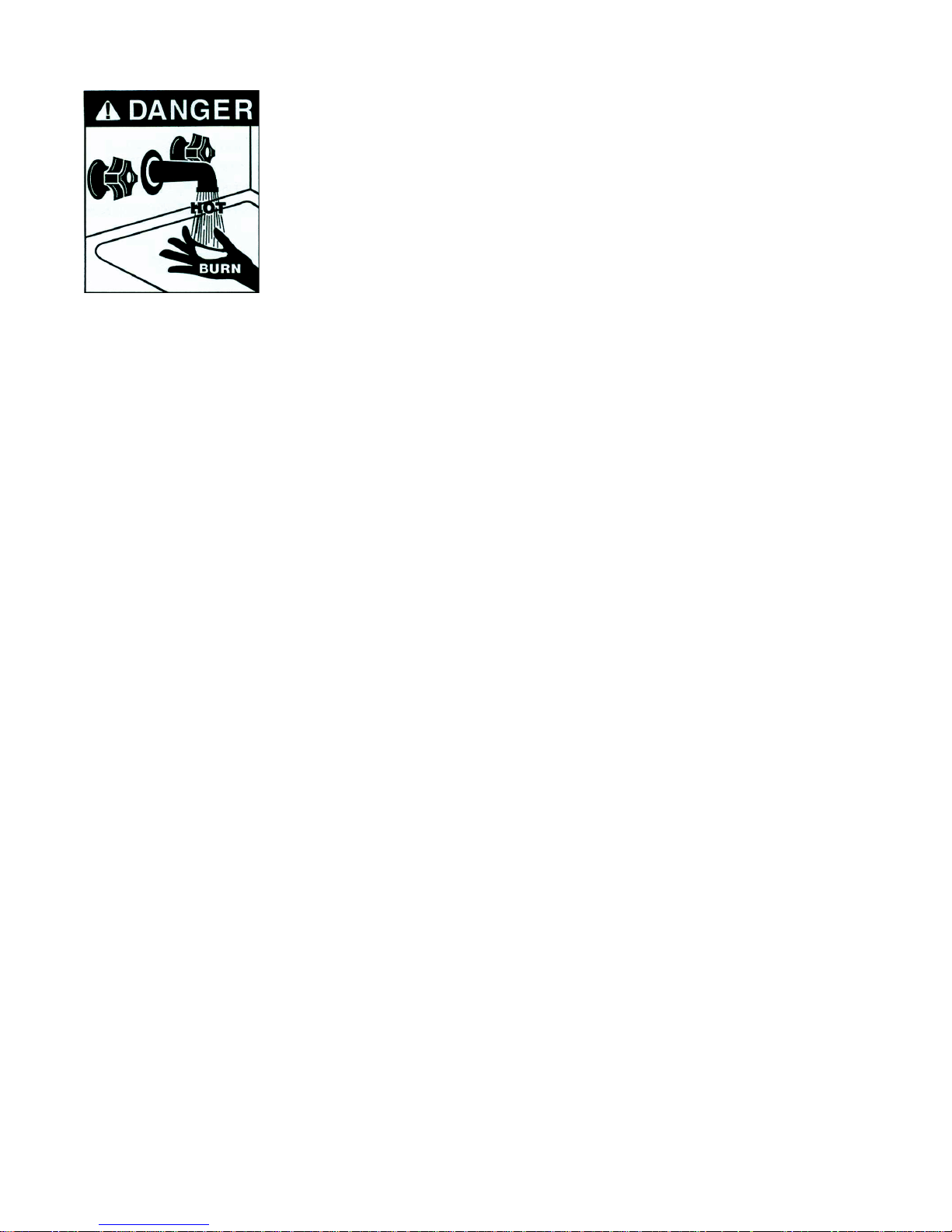
• Water temperature over 125°F can cause severe burns instantly or death from
scalds.
• Children, disabled and elderly are at the highest risk of being scalded.
• See instruction manual before setting temperature at the water heater.
• Feel water before bathing or showering.
• Temperature limiting valves are available, see manual.
The temperature of the water in the heater is regulated by an adjustable, automatic,
temperature control which uses surface mounted thermistors located behind the
jacket. These automatic controls are set at the factory to maintain a water
temperature of 120°F. Although these controls are designed to industry standards,
they can fail to control temperature properly without any notice, and therefore should be tested periodically
for your protection.
To perform the test: Turn on the hot water faucet and measure the maximum temperature with an accurate
thermometer. If the temperature is above the safe limits for your circumstances call a service technician to
adjust or replace the control.
DANGER: IF YOU DISCOVER EXTREME HOT WATER COMING FROM THE FAUCET,
IMMEDIATELY SHUT OFF THE ELECTRICITY AND GAS AT THE MAIN SWITCH AND CALL
COMPETENT SERVICE PERSONNEL. ANY OVERHEATED WATER HEATER IS A POTENTIAL
HAZARD TO LIFE AND PROPERTY. DO NOT OPERATE UNTIL THE SOURCE OF THE PROBLEM
HAS BEEN DETERMINED AND ELIMINATED.
WARNING: Corrosion of the flue ways and vent system may occur if air for combustion contains certain
chemical vapors. This can result in failure and risk of suffocation.
WARNING: Attic and/or exhaust fans operating in conjunction with a water heater can result in carbon
monoxide poisoning and death.
*Operating these fans can produce a negative draft in the area of the water heater and prevent the products
of combustion from exhausting through the chimney or vent pipe. The venting of the water heater should be
inspected by a qualified service technician at the time of installation and periodically thereafter to ensure a
down-draft condition does not exist. Do not obstruct the flow of combustion and ventilating air.
WARNING: Generally, after two weeks or more of non-use, hydrogen gas can be produced in a hot water
system. Hydrogen gas is extremely flammable. To reduce risk of injury caused by this hydrogen, it is
recommended to run the hot water faucet for several minutes at the kitchen sink before using any electrical
appliance connected to the hot water system. If hydrogen is present, typically there will be an unusual noise
similar to air escaping through the pipes. There should be no smoking or open flame near the faucet at the
time it is open.
NOTICE: Should overheating occur or the gas supply fails to shut off, turn off the manual gas control valve
to the appliance.
Page 7

7
IN THE STATE OF MASSACHUSETTS ONLY
(Check up to date local codes and regulations for other jurisdictions)
(a) For all horizontally vented gas fueled equipment installed in every dwelling, building or structure used in whole
or in part for residential purposes, including those owned and operated by the Commonwealth and where the side
wall exhaust vent termination is less than seven (7) feet above finished grade in the area of the venting, including but
not limited to decks and porches, the following requirements shall be satisfied:
1. INSTALLATION OF CARBON MONOXIDE DETECTORS At the time of installation of the side wall
horizontal vented gas fueled equipment, the installing plumber or gas fitter shall observe that a hard wired carbon
monoxide detector with an alarm and battery back-up is installed on the floor level where the gas equipment is to be
installed and on each additional level of the dwelling, building or structure served by the equipment. It shall be the
responsibility of the property owner to secure the services of qualified licensed professionals for the installation of
hard wired carbon monoxide detectors. a. In the event that the side wall horizontally vented gas fueled equipment is
installed in a crawl space or an attic, the hard wired carbon monoxide detector with alarm and battery back-up may
be installed on the next adjacent floor level.
b. In the event that the requirements of this subdivision cannot be met at the time of completion of installation, the
owner shall have a period of 30 days to comply with the above requirements; provided, however, that during said 30
day period a battery operated carbon monoxide detector with an alarm shall be installed.
2. APPROVED CARBON MONOXIDE DETECTORS Each carbon monoxide detector as required in accordance
with the above provisions shall comply with NFPA 720 and be ANSI/UL 2034 listed and IAS certified.
3. SIGNAGE A metal or plastic identification plate shall be permanently mounted to the exterior of the building
at a minimum height of eight (8) feet above grade directly in line with the exhaust vent terminal for the horizontally
vented gas fueled heating water heater or equipment. The sign shall read, in print size no less than one-half (1/2) inch
in size, “GAS VENT DIRECTLY BELOW. KEEP CLEAR OF ALL OBSTRUCTIONS”
(plate included with water heater).
4. INSPECTION The state or local gas inspector of the side wall horizontally vented gas fueled equipment shall not
approve the installation unless, upon inspection, the inspector observes carbon monoxide detectors and signage
installed in accordance with the provisions of 248 CMR 5.08(2)(a)1 through 4.
(b) EXEMPTIONS: The following equipment is exempt from 248 CMR 5.08(2)(a)1 through 4:
1. The equipment listed in Chapter 10 entitled “Equipment Not Required To Be Vented” in the most current
edition of NFPA 54 as adopted by the Board; and
2. Product Approved side wall horizontally vented gas fueled equipment installed in a room or structure separate
from the dwelling, building or structure used in whole or in part for residential purposes.
(c) MANUFACTURER REQUIREMENTS – GAS EQUIPMENT VENTING SYSTEM PROVIDED: When the
manufacturer of Product Approved side wall horizontally vented gas equipment provides a venting system design or
venting system components with the equipment, the instructions provided by the manufacturer for installation of the
equipment and the venting system shall include:
1. Detailed instructions for installation of the venting system design or the venting system components; and
2. A complete parts list for the venting system design or venting system.
(d) MANUFACTURER REQUIREMENTS – GAS EQUIPMENT VENTING SYSTEM NOT PROVIDED:
When the manufacturer of a Product Approved side wall horizontally vented gas fueled equipment does not provide
the parts for venting the flue gases, but identifies “special venting systems”, the following requirements shall be
satisfied by the manufacturer:
1. The referenced “special venting system” instructions shall be included with the water heater or equipment
installation instructions; and
2. The “special venting system” shall be Product Approved by the Board, and the instructions for that system shall
include a parts list and detailed installation instructions.
(e) A copy of all installation instructions for all Product Approved side wall horizontally vented gas fueled
equipment, all venting instructions, all parts list for venting instructions, and/or all venting design instructions shall
remain with the water heater or equipment at the completion of the installation.
Page 8

8
Outline Dimensions
Figure 1 - Tank Assembly (55k Btu Unit on top, 110k Unit on bottom)
Page 9
9
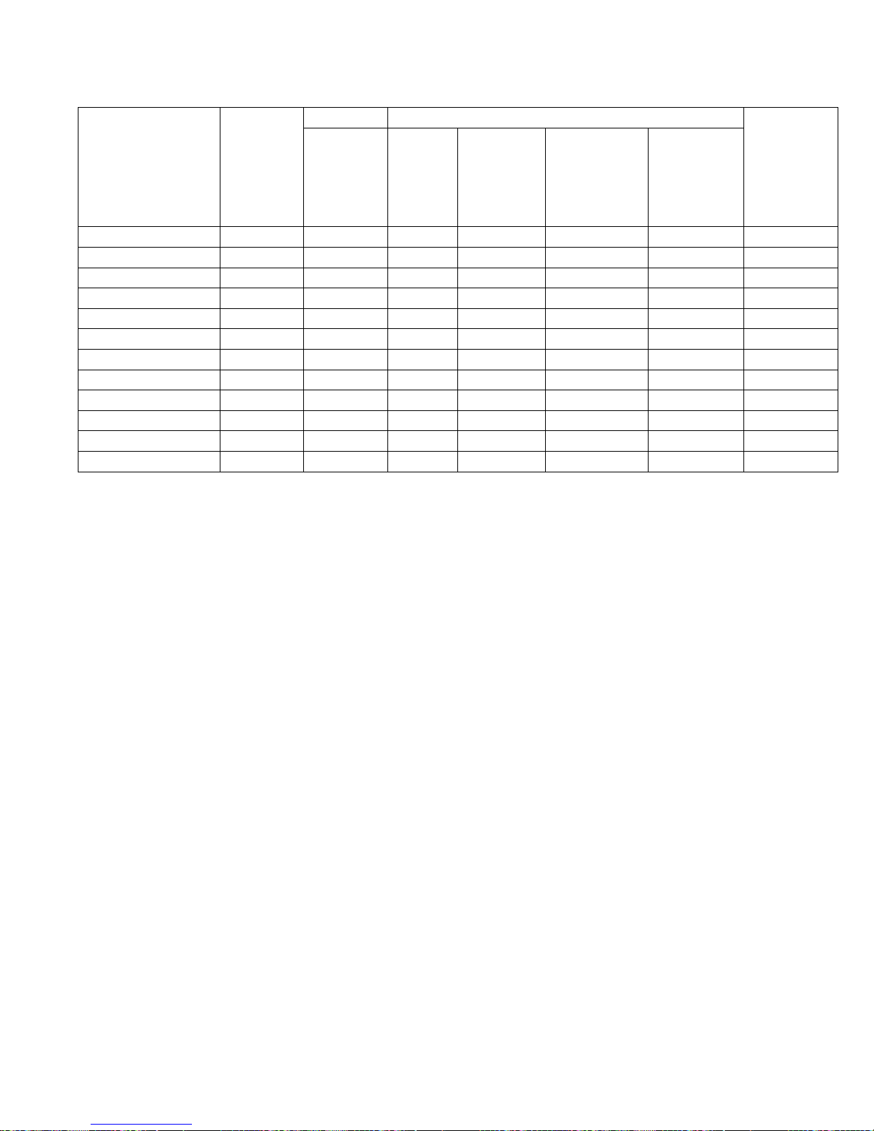
Base Model
Number
Storage
Capacity
(Gallons)
Dimensions (Inches)
Shipping
Weight
(lbs.)
Tank
Diameter
“A”
Overall
Depth
“B”
Overall
Height
“C”
Floor to
Relief Valve
“D”
Floor to
Cold
Water
Inlet
“E”
GSE55-C-40SL
40
26
38.625
31.5
25.25
7.75
246
GSE55-C-50SL
50
28
40.625
36
27.5
7.75
286
GSE55-C-65SL
65
26
38.625
46.25
39.375
7.875
294
GSE55-C-80SL
80
26
38.625
57.25
49.875
7.875
351
GSE55-C-100SL
100
26
38.625
67.50
60.375
7.875
409
GSE55-C-120SL
120
28
40.625
67.75
60.375
7.875
438
GSE110-C-40SL
40
26
40.025
31.5
25.25
7.75
286
GSE110-C-50SL
50
28
42.025
36
27.5
7.75
326
GSE110-C-65SL
65
26
40.025
46.25
39.375
7.875
334
GSE110-C-80SL
80
26
40.025
57.25
49.875
7.875
411
GSE110-C-100SL
100
26
40.025
67.50
60.375
7.875
469
GSE110-C-120SL
120
28
42.025
67.75
60.375
7.875
498
Table 1- Model Specific Dimensional Data
Page 10

10
Electrical
• This water heater has a power cord with a standard 120V three-prong plug.
• Power cord should be plugged directly into a proper 120V wall outlet. Power strips and extension cords
should not be used.
• Maximum amperage draw is .7 amps for single heat exchanger model, 1.4 amps for double heat
exchanger model.
Gas
• The maximum BTU input is 55,000 BTU per hour for single heat exchanger model, 110,000 BTU per
hour for double heat exchanger model.
• The minimum BTU input is 18,000 BTU per hour.
• This water heater has a 1/2 inch female NPT gas fitting.
• See Gas Installation section for more information.
Page 11

11
2.0 INSTALLATION
WARNING / CAUTION
DO NOT TURN ON THE ELECTRIC POWER SUPPLY to this equipment until heater is completely filled
with water and all air has been released. If the heater is NOT filled with water when the power is turned on,
the heating elements will burn out (if equipped), and can cause damage to gas heat exchanger.
For protection against excessive pressures and temperatures, local codes require the installation of a
temperature-and-pressure (T&P) relief valve certified by a nationally recognized laboratory that maintains
periodic inspection of production of listed equipment of materials, as meeting the requirements for Relief
Valves and Automatic Gas Shutoff for Hot Water Supply Systems, ANSI Z21.22. THE CUSTOMER IS
RESPONSIBLE TO PROTECT PROPERTY AND PERSONNEL FROM HARM WHEN THE VALVE
FUNCTIONS.
All water heaters have a risk of leakage at some unpredictable time. IT IS THE CUSTOMER'S
RESPONSIBILITY TO PROVIDE A CATCH PAN OR OTHER ADEQUATE MEANS, SO THAT THE
RESULTANT FLOW OF WATER WILL NOT DAMAGE FURNISHINGS OR PROPERTY.
Before doing anything, inspect the tank and all parts to assure that no parts are faulty or damaged from
shipping.
Installation Safety Notes
1. Tank is to be completely filled with water and all air is to be vented before energizing. Do not turn on
water heater if cold water supply shut off valve is closed.
2. Due to the rigors of transportation, all connections should be checked for tightness before heater is
placed in operation.
3. Safety relief valve must be installed in the tapping provided.
4. The refractory material used in heating elements may absorb some moisture during transit, periods of
storage, or when subjected to a humid environment. This moisture absorption results in a cold insulation
resistance of less than twenty (20) megohms. If this heater has been subjected to the above condition,
each heating element must be checked for insulation resistance before energizing. A low megohm
condition can be corrected by removing the terminal hardware and baking the element in an oven at
350°F -700°F for several hours or until the proper megohm reading is obtained.
5. KEEP AWAY FROM LIVE ELECTRICAL CIRCUITS.
Do not perform any maintenance, make any adjustments, or replace any components inside the control
panel with the high voltage power supply turned on. Under certain circumstances, dangerous potentials
may exist even when the power supply is off. To avoid casualties, always turn the power supply safety
switch to off, turn the charge or ground the circuit before performing any maintenance or adjustment
procedure.
6. The unit is designed to operate at pressure not more than 150 psi.
7. Generalized instructions and procedures cannot anticipate all situations. For this reason, only qualified
installers should perform the installations. A qualified installer is a person who has licensed training and
a working knowledge of the applicable codes regulation, tools, equipment, and methods necessary for
safe installation of an electric resistance water heater. If questions regarding installation arise, check
your local plumbing and electrical inspectors for proper procedures and codes. If you cannot obtain the
required information, contact the company.
Page 12

12
8. In the event of overheating, fire, flood, or physical damage, turn off all power and gas to your water
heater. Do not power the heater until it has been examined by a trained professional.
9. Do not store or use gasoline or other flammable vapors and liquids, such as adhesives or paint thinner,
in the vicinity of this water heater. If such flammable materials must be used near the unit, open nearby
doors and windows to allow for ventilation.
Installer Responsibilities
A qualified installer is a licensed person who has appropriate training and a working knowledge of the applicable codes,
regulations, tools, equipment and methods necessary to install a water heater. The Installer assumes all responsibility for a
safe installation and that it meets the requirements of the water heater instruction manuals, as well as National and local
installation codes. It is also the installer’s responsibility to inform the User/Owner of their obligation with respect to the
description under “User Responsibilities”. Failure to follow this warning could result in fire, serious injury, or death.
Water Heater Placement
1. Place the heater on a solid foundation in a clean, dry location nearest to the point of most
frequent hot water use. If the heater is to be raised off the floor, the entire bottom of the heater
should be supported by a solid surface.
2. The water heater must be installed with a minimum clearance of 12” on top of the water heater,
24” in front of the housing, and 18” to the left of the housing.
3. If the water heater is installed directly on carpeting, a metal or wood panel extending beyond the
full width and depth of the appliance by at least 3 in (76.2 mm) in any direction. If the water
heater is installed in an alcove or closet, the entire floor shall be covered by the panel.
4. Do not install in an area where flammable liquids or combustible vapors are present.
5. The water heater should be protected from freezing and waterlines insulated to reduce energy
and water waste.
6. Locations with warmer ambient air (ex. furnace rooms) are more advantageous as they provide
“free” heat.
7. The water heater will produce exhaust gas which must be piped outdoors, so installation must be
in a location where proper ventilation can be set up. See the following section on venting for proper
installation of ventilation.
NOTICE: If a water heater is installed in a closed water supply system, such as one having a backflow
preventer in the cold water supply line, means shall be provided to control thermal expansion. Contact the
water supplier or local plumbing inspector on how to control this situation.
WARNING: Do not store or use gasoline or other flammable vapors and liquids in the vicinity of this or any
other appliance. Failure to follow instructions could result in explosion causing property damage, serious
injury, or death.
Ventilation
The Hubbell Condensing Gas Water Heater is a water heater requiring a “direct venting system” designed for
pressurized venting. The exhaust vent must be piped to the outdoors, using the vent materials and rules
outlined in this section. Under no conditions may this unit vent gases into a masonry chimney unless it is
vacant and utilizes the approved venting material and rules.
NOTE: Common venting or two separate direct vents can be used if you are installing a 110k Btu unit, as this
unit has two separate condensing heat exchangers that need exhaust to be vented outdoors. If this unit is
Page 13
13
commonly vented, it may only be commonly vented with itself and must satisfy all relating safety codes and
regulations including use of backflow preventers and increasing pipe diameter when additional exhaust lines
connect. It is recommended to increase the pipe diameter to at least 4” PVC if the exhaust lines are combined.
DANGER: Vent and Air-inlet are to be piped separately. This water heater cannot share a common vent or
air-inlet with multiple appliances. Failure to comply will result in serious injury or death.
Removing an Existing Water Heater from Common Venting System
DANGER: Do not install this water heater into a common venting system with any other appliances. Failure
to comply with this warning will cause flue gas spillage and leech carbon monoxide emissions into the
surrounding air resulting in serious injury or death.
WARNING: When an existing water heater is removed from a common venting system, the common venting
system is likely to be too large for proper venting of the remaining appliances connected to it.
Direct Vent Installation
As a direct vent water heater, the combustion air-inlet must also be piped directly to the outdoors using the
methods described in this section and in accordance with the National Fuel Gas Code, ANSI Z223.1 (U.S.),
or CSA B149.1 (Canada) and local requirements.
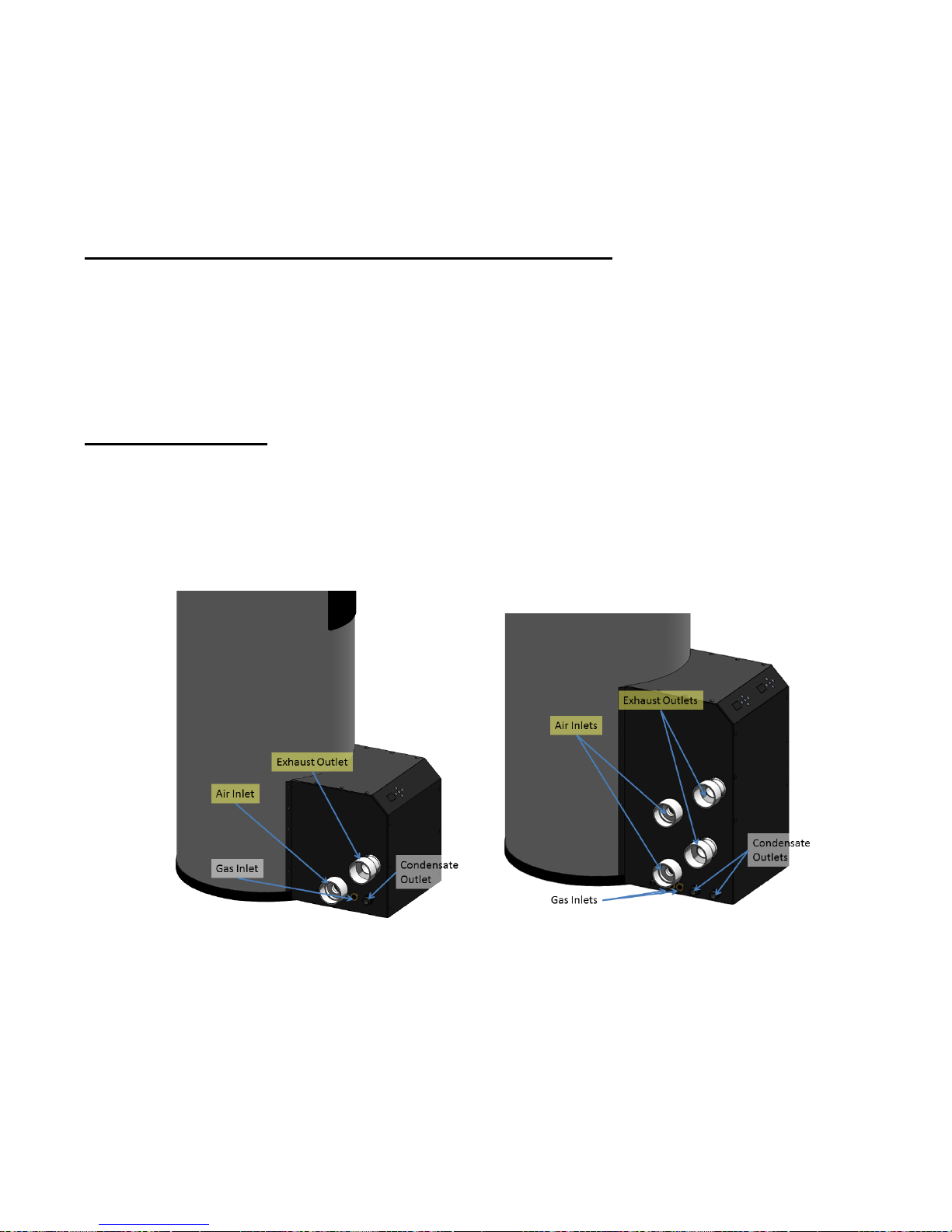
Figure 2 - Ventilation Connections
WARNING: Make up air requirements for the operation of exhaust fans, kitchen ventilation systems, clothes
dryers, and fireplaces shall be considered in determining the adequacy of a space to provide combustion air
requirements. Failure to ensure adequate make up air to all appliances may result in personal injury or death.
NOTICE: The water heater shall be located so as not to interfere with proper circulation of combustion,
ventilation, and dilution of air.
Single Unit Heater on Left, Double Unit Heater on Right
Page 14
14
Combustion Air-inlet Contamination
Be careful not to locate the air-inlet termination in an area where contaminants can be drawn in and used for
combustion. When deciding on a location for the vent and combustion air-inlet terminals on an exterior wall,
be sure to allow at least 12 in. between them to prevent drawing in exhaust with the air. These terminals should
also be located at least 1 ft. above grade or average snowfall height (whichever height is greater) to prevent
blockage. Combustion air containing dust, debris, or airborne contaminants will drastically increase the
required maintenance and may cause a corrosive reaction in the heat exchanger, which could result in
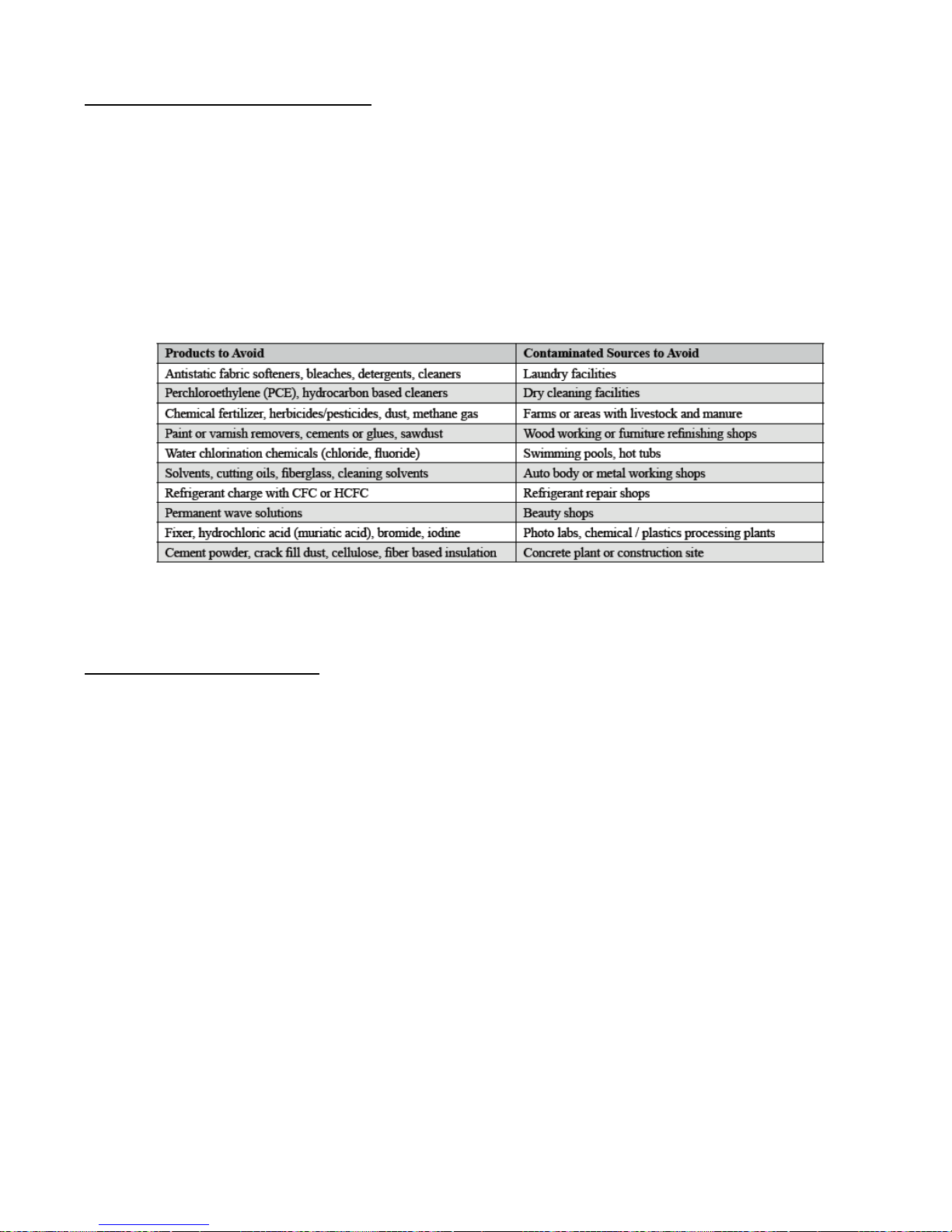
premature failure, fire, serious injury, or death. See the following table for a list of areas to avoid when
terminating air-intake piping.
Table 2 - Possible Ventilation Contaminants
WARNING: Do not store or use gasoline or other flammable vapors and liquids in the vicinity of this or any
other appliance. Failure to follow instructions may result in serious injury or death.
Water Heater Vent/Air Piping
Each water heater is equipped with a (or two, if you have the 110k Btu dual heat exchanger unit) short piece(s)
of approved CPVC vent pipe. Insert one end into the water heater flue outlet adapter and cement the other to
field venting. The CPVC vent pipe should extend fully into the water heater flue outlet adapter and seal with
the O-ring provided. Ensure that the venting system does not apply a load or strain on the water heater flue
outlet adapter. The manufacturer recommends using two elbows to create a swing joint to reduce potential
strain on vent piping and cemented joints.
WARNING: Gasket Seating – Improper seating can cause leakage and eventual failure or the sealing gasket.
Failure to follow these instructions may result in serious injury or death.
WARNING: PVC Exhaust Venting – DO NOT insert PVC pipe directly into the water heater exhaust adapter
as it may not seat in the adapter. Use only the manufacturer supplied PVC pipe. Failure to follow these
instructions may result in gasket failure and/or the dislodging of the exhaust pipe from the water heater
adapter, resulting in property damage, serious injury, or death.
WARNING: Polypropylene or Stainless Steel Venting – When using polypropylene or stainless steel piping,
the appropriate water heater adapters must be used to transition the water heater vent connections to accept
the respective polypropylene or stainless steel venting. Failure to use the correct adapter will result in flue gas
leakage resulting in property damage, serious injury, or death.
Page 15
15
DANGER: Exhaust venting must be supported to reduce strain on piping joints. Failure to follow these
Pipe
Size
Gas
Length
ft.
Number of Elbows (90’s or 45’s) and Equivalent Feet
1 2 3 4 5 6 7
8
2”
NG
40
30
10
20 - - - - - 3”
NG
100
90
80
70
60
50
40
30
20
instructions may result in damage, serious injury, or death.
NOTICE: In Canada, the first 3 ft (915mm) of vent piping must be readily accessible for inspection.
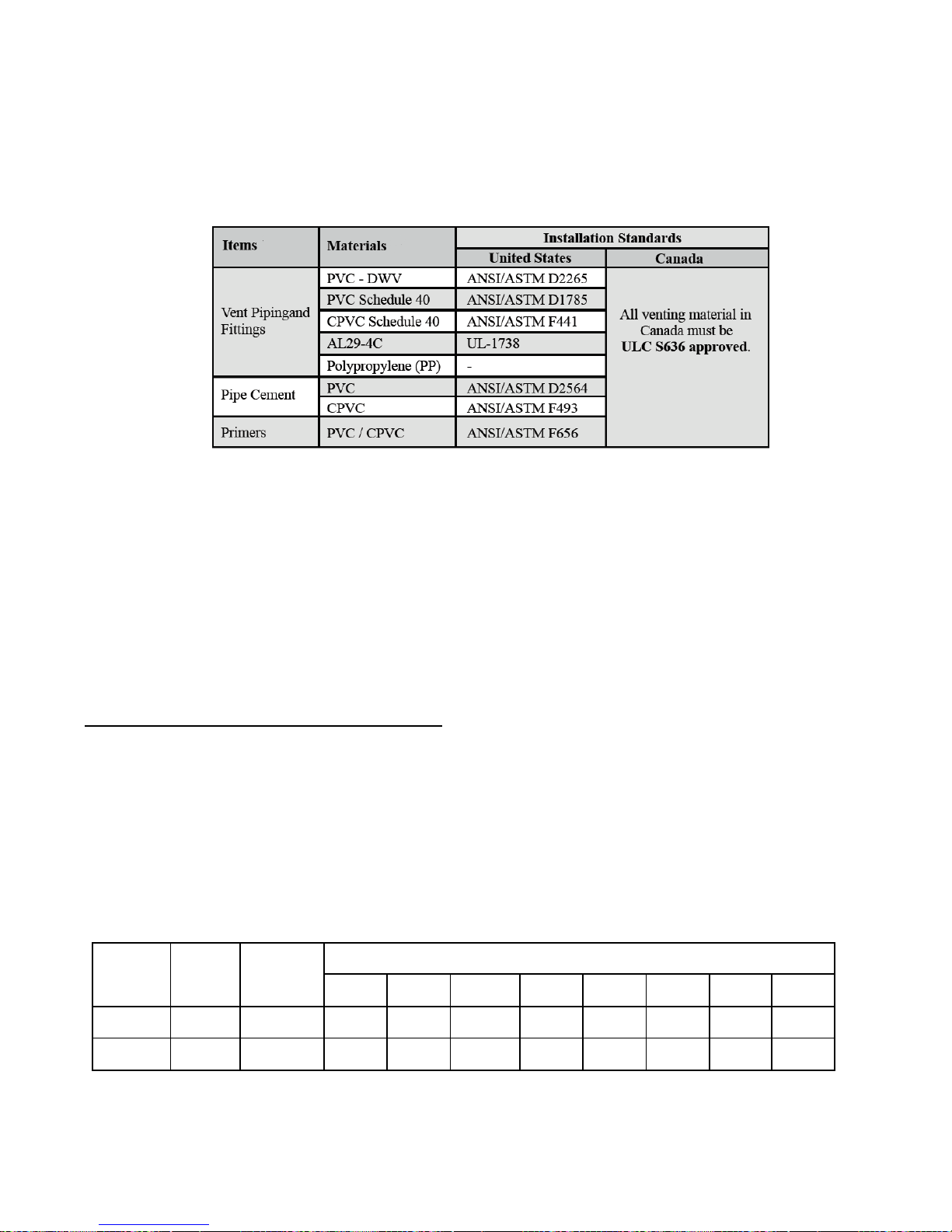
Table 3 - Vent/Air-inlet Pipe Materials
WARNING: All vent and air-inlet-materials installed on gas fired appliances in CAN/US must meet the
standards for the region in which they are installed. Failure to comply may result in fire, serious injury, or
death.
WARNING: The use of cellular core PVC (ASTM F891), cellular core CPVC, or Radel (polyphenol-sulfone)
in the exhaust venting system is prohibited. Failure to follow these instructions may result in property damage,
personal injury, or death.
WARNING: Covering non-metallic vent pipe and fittings with thermal insulation is prohibited. Failure to
follow these instructions may result in property damage, personal injury, or death.
Vent and Air-inlet Pipe Length Determination
Use the provided inlet and outlet adapters to attach duct work to the water heater. When using 3” piping, an
additional adapter is required from 2” to 3”.
Use the table below to determine the maximum pipe length that can be used. The table calculates sweep, 90°
elbows, and 45° elbows at 10 equivalent feet each.
Table 4 - Vent and Air-inlet (Single Heat Exchanger Ventilation)
Page 16

16
Table 5 - Vent and Air-inlet Pipe Length Determination (Common Vented Double Unit)
Pipe
Size
Gas
Length
ft.
Number of Elbows (90’s or 45’s) and Equivalent Feet
1 2 3 4 5 6 7 8 3”
NG
35
25
15 5 - - - - -
4”
NG
150
140
130
120
110
100
90
80
70
NOTICE: 1 foot of piping minimum required before first elbow.
NOTICE: The length of one vent pipe (air-inlet or exhaust) may not exceed the length of the other vent pipe
by more than 20 equivalent feet.
Termination– Direct Vent Installation
The venting system of this water heater must be terminated using field supplied piping to construct a “TwoPipe” termination.
IMPORTANT: PVC In Canada – Authorities in some jurisdictions may not allow the use of any PVC venting
materials with condensing water heaters; check with the local safety inspector to verify compliance prior to
installing a PVC Vent Kit with a water heater.
Page 17
17
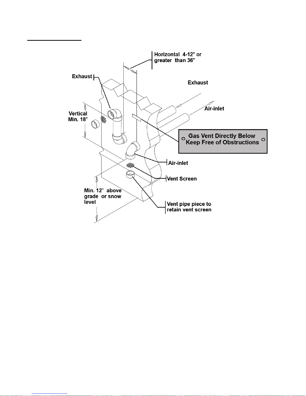
Sidewall Terminations
Figure 3 - Two Pipe Termination (Sidewall)
Page 18
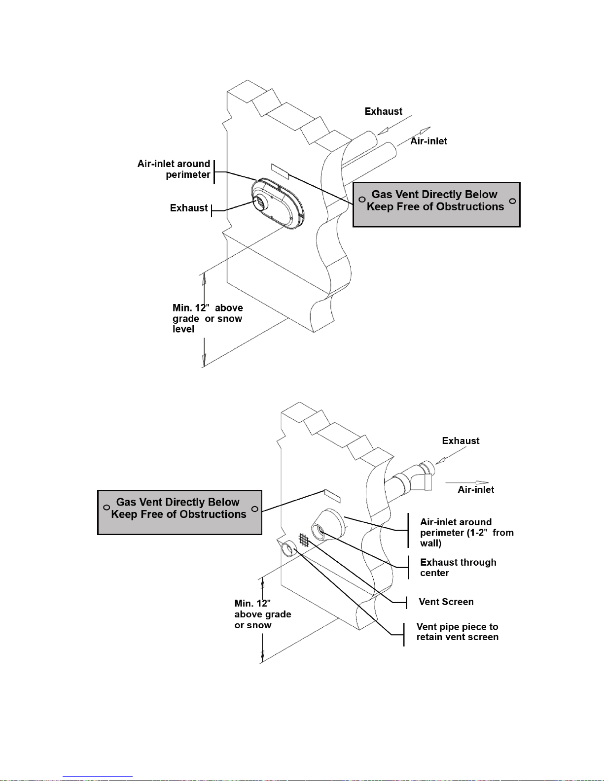
18
Figure 4 - Two Pipe Low Profile Termination (Sidewall)
Figure 5 - Two Pipe Concentric Termination (Sidewall)
Page 19
19
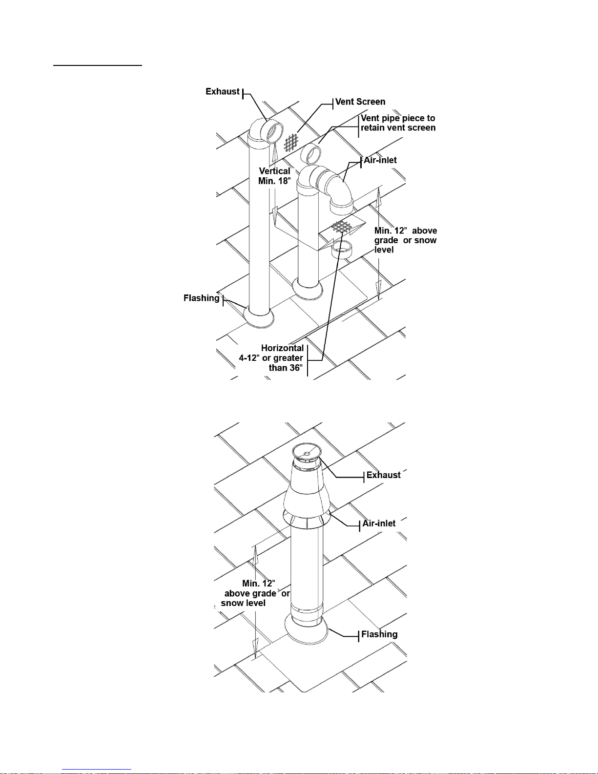
Roof Terminations
Figure 6 - Two Pipe Termination (Roof)
Figure 7 - Two Pipe Concentric Termination (Roof)
.
Page 20

20
Venting Rules and Guidelines:
1. Prevailing Winds: Ensure the vent is located where it will not be exposed to normal prevailing winds.
2. Combustion Air-inlet Contamination: Air for combustion must be drawn from an area free of dust and
contaminants. Combustion air containing chemicals such as chloride, fluoride, bromine, iodine, or
dust and debris will cause corrosion damage of the heat exchanger voiding your Hubbell warranty.
3. Vertical Separation: The exhaust must be a minimum of 18 inches above the air inlet, and the air inlet
must always be a minimum of 12 inches plus snow allowance above any surface that will support
snow (two feet plus snow allowance is highly recommended). Consult your weather office for the
maximum typical snowfall for your region.
4. Horizontal Separation: The horizontal distance between the inlet and exhaust must be a minimum of
4 inches center to center.
5. Wall Flashing: Under normal operating conditions this water heater will produce a plume of white
gases and should be taken into consideration when selecting an adequate location. A 36 inch diameter
stainless, plastic, or vinyl shield can be used to flash the exterior of the building.
6. Flue Gas Hazard: Position the vent termination where vapors cannot make accidental contact with
people and pets or damage nearby shrubs or plants.
7. Elbow Extension: Elbows on the outside of a wall must be no more than ½” away from the wall.
8. Vent Sloping: All indoor exhaust piping must be on a slope back to the water heater a minimum of ¼”
per linear foot of vent. For applications where excessive condensation is possible, ½” per linear foot
is recommended.
9. Vent supports: Where required, vent and air-inlet piping shall be secured to the wall for more rigidity.
All interior vent pipe shall be supported a minimum of every 36 inches.
10. Roof Exhaust: In all roof applications the discharge must point away from the pitch of the roof.
11. Roof Flashing: Install adequate flashing where the pipe enters the roof to prevent water leakage.
12. Rain Cap: Install and seal a rain cap over existing chimney openings in vacant chimney applications.
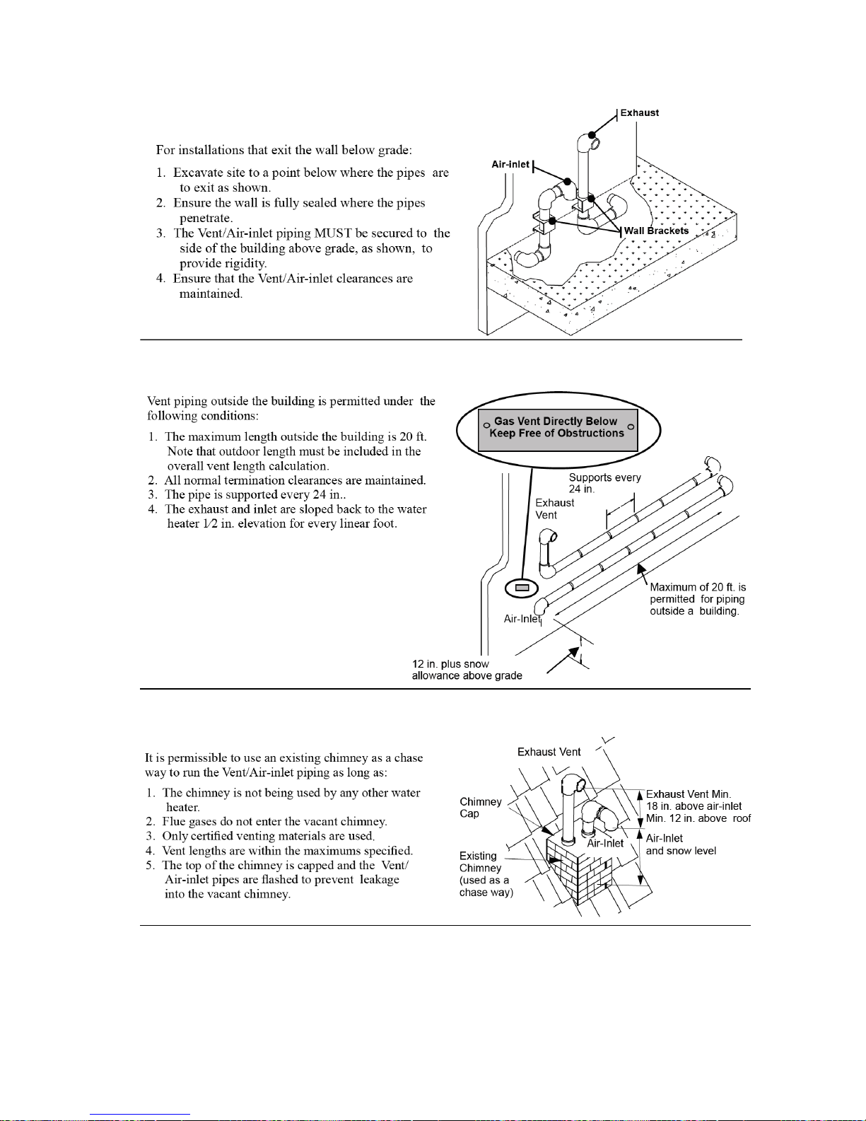
13. Venting Below Grade: For installations that exit the wall below grade, refer to Figure 8.
14. Condensate Hazard: Do not locate vent over public walkways, driveways, or parking lots. Condensate
could drip and freeze resulting in slip hazard or damage to vehicles and machinery.
15. Warning Plate: For sidewall venting, install a warning plate “Gas Vent Directly Below” directly above
(within 4 ft. vertically) the location of the air-inlet pipe so it is visible from at least 8 ft. away.
16. Wall Thickness: Direct vent terminations are designed to work with any standard wall thickness.
Installation guidelines for min/max wall thickness are as follows: min.=1 in., max.=60 in..
17. Venting Options: Due to potential moisture loading (build-up) along the exterior wall, sidewall venting
may not be the preferred venting option. Refer to Figure 6 and Figure 7 for roof top venting options.
WARNING: The vent for this water heater shall not terminate over public walkways or near soffit vents or
crawl space vents or other areas where condensate of vapor could create a nuisance or hazard or cause property
damage; or where condensate or vapor could cause damage or could be detrimental to the operation of
regulators, relief valves, or other equipment.
Page 21
21
Figure 8 –Venting Below Grade
Figure 9 - Outdoor Venting Guidelines
Figure 10 – Existing Chimney Chase Way
DANGER: Under no circumstances may an existing chimney or chase-way be used to vent or provide
combustion intake air to the water heater. Failure to follow these instructions will result in fire, property
damage, serious injury or death.
Page 22
22
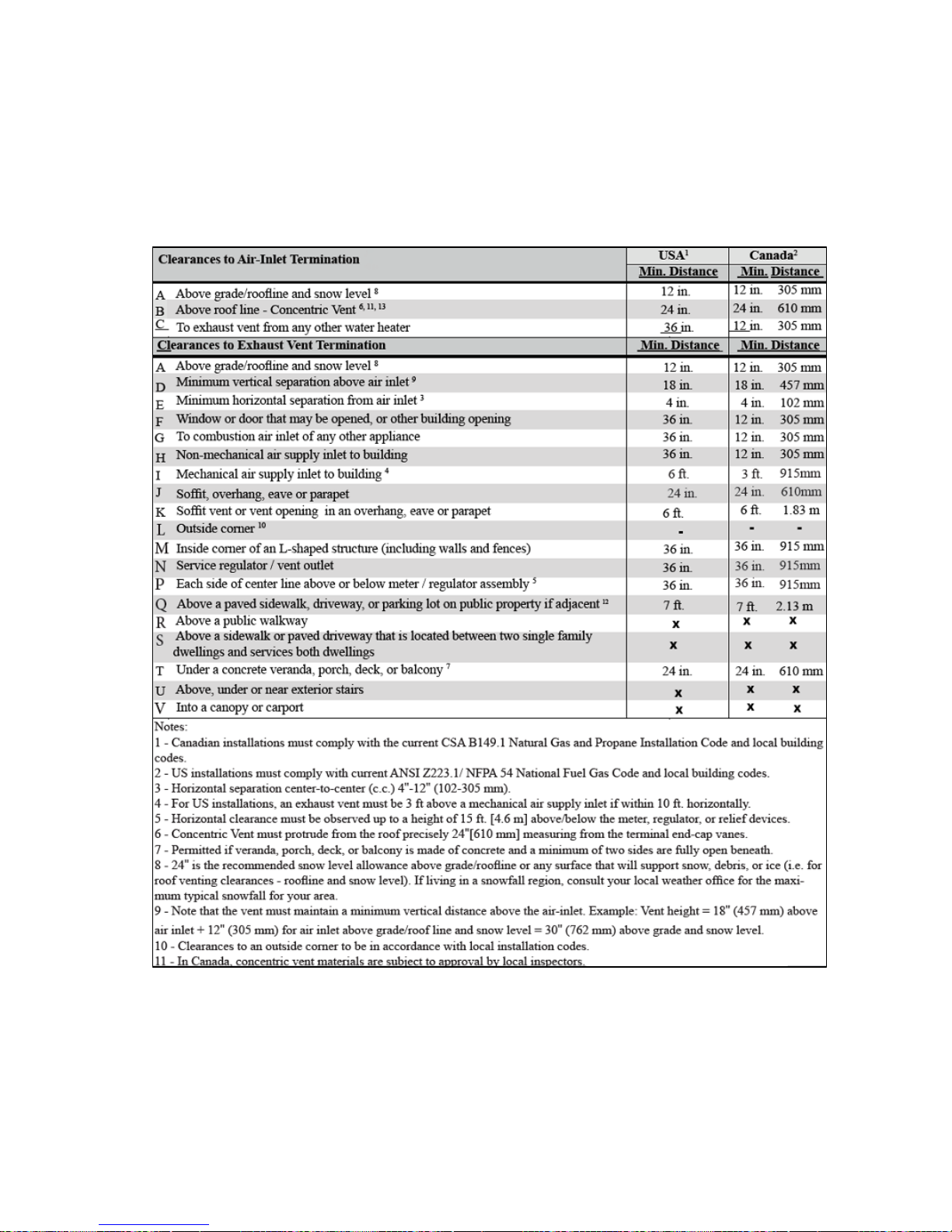
WARNING: The quick reference table below is to be read in conjunction with the Venting Rules and
Guidelines in this section. The instructions detailed in this section are a combination of Hubbell specific and
National Gas Code restrictions. Compliance alone doesn’t insure a satisfactory installation as good common
sense must also be applied. Failure to follow these instructions may result in fire, property damage, serious
injury or death.
Table 6 - Vent and Air-intake Termination Clearances
Page 23
23
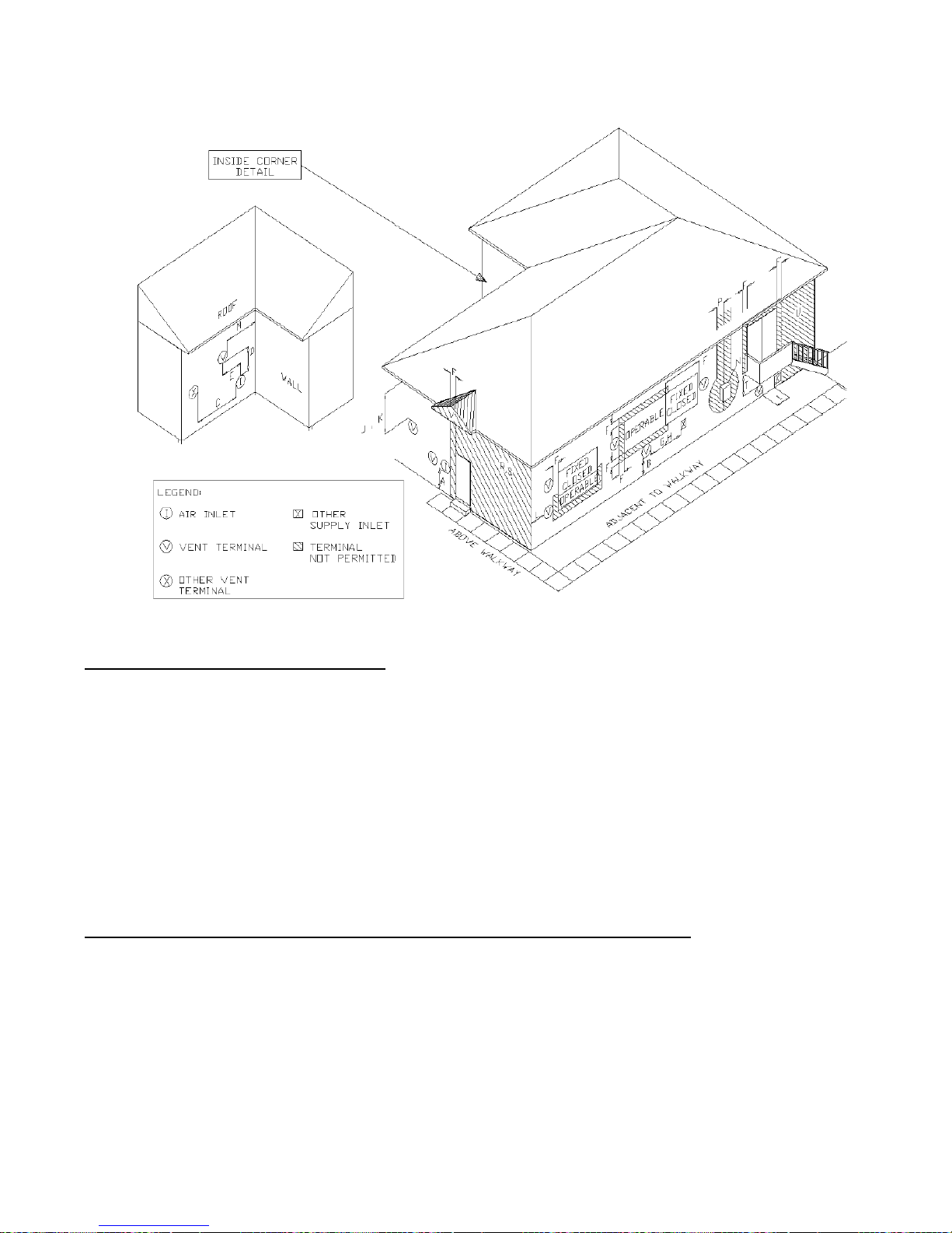
Figure 11 - Basic Ventilation Layout
Flammable Solvents and Plastic Piping
Due to the extremely flammable characteristics of most glues, cements, solvents, and primers used in the
process of joining plastic vents and air-inlet pipes explosive solvent vapors must be evacuated from the vent
and air-intake prior to start-up. Avoid using excess cement or primer that may lead to pooling inside the pipe
assembly. Fresh assembled piping assembly should be allowed to cure for a minimum of 8 hours before
applying power to the gas fired appliance. Refer to Mandatory Pre-commissioning Procedure for Plastic
Venting in this section.
DANGER: Flammable Cements and Primers – It is the installers’ responsibility to familiarize themselves
with the hazard associated with explosive solvents and to take all precautions to reduce these risks. Failure to
follow these instructions can cause explosions, property damage, injury, or death.
Mandatory Pre-commissioning Procedure for Plastic Venting (PVC or CPVC)
WARNING: Do not apply power to the water heater prior to step 4 in the Mandatory Pre-commissioning
Procedure for Plastic Venting.
WARNING: Spark Igniter Cable – Maintaining a minimum 2 inch separation between spark igniter circuit
and conductors. Failure to follow instructions may result in component failure, injury, or death.
1. Working with the power turned off to the water heater, completely install the vent and air-inlet system,
securely cementing joints together. If possible, allow primers/cements to cure for 8 hours before firing
the burner. If curing time is less than 8 hours, proceed with the following steps.
Page 24
24
2. Maintain the water heater gas supply shut-off valve in the off position.
3. Disconnect both electrical leads going to the spark ignitor. Refer to the warning regarding Spark Igniter
Cable.
4. Turn power on to the water heater and apply a heat demand.
5. Allow for 3 complete trials for ignition, consisting of pre and post purge of the combustion blower,
until an ignition lockout occurs. Repeat this process two more times (i.e. 9 complete ignition sequences
in total).
6. Turn power off and reconnect the electrical leads to the igniter.
Condensate Drain
This unit produces liquid condensate in the heat exchanger and venting system as a product of combustion.
Steps must be taken to ensure that condensate does not collect in the venting system; therefore, all exhaust
piping must slope back to the water heater a minimum ¼” per linear foot of vent. Condensate must be
drained from the unit into a household drain. Check with your municipality or local gas company to
determine if the disposal of combustion condensate is permitted in your area (e.g. in the State of
Massachusetts the condensate must be neutralized prior to entering a drain.)
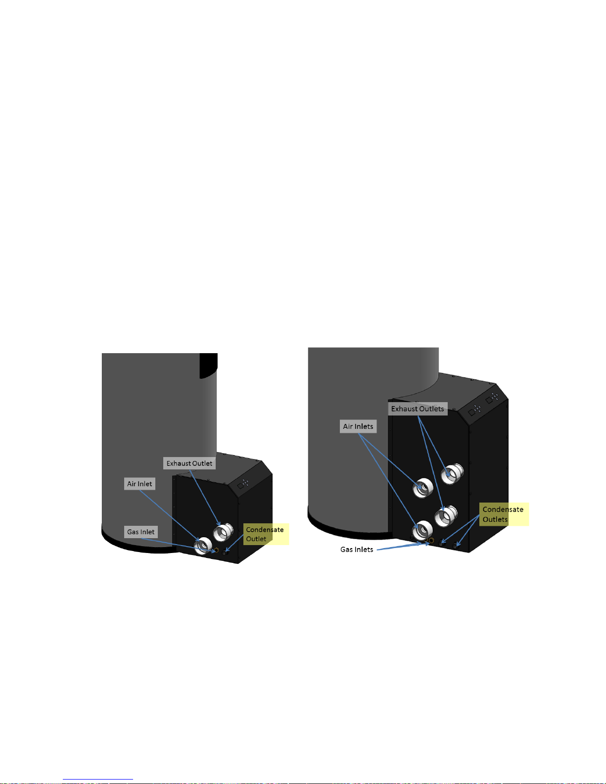
Figure 12 - Condensate Outlet Location
The following are important notes that must be taken into consideration when constructing the condensate
drain system:
• DO NOT install condensate lines outside, as this could lead to a frozen or blocked drain. A frozen or
blocked drain will cause the condensate to fill the combustion chamber. This will result in no heat as
the unit will shut down, and damage to the flame sensor and components can occur.
• NEVER use copper, steel, or galvanized piping in the construction of the condensate disposal system
as condensate is very corrosive and will corrode most metallic drains and sewer pipes.
• When a condensate pump is used or required, select a pump that is designed for residential furnaces.
Single Unit Heater on Left, Double Unit Heater on Right
Page 25
25
WARNING: If the combustion chamber has been flooded due to the condensate drain backing up, or for any
other reason, the combustion chamber door must be removed and the inside of the water heater must be
inspected for component damage. Failure to follow these instructions may result in fire, property damage,
serious injury, or death.
Gas Installation
WARNING: This device is factory equipped to operate with natural gas. If propane gas is to be used with
this device, the installation of a conversion kit is required prior to operation.
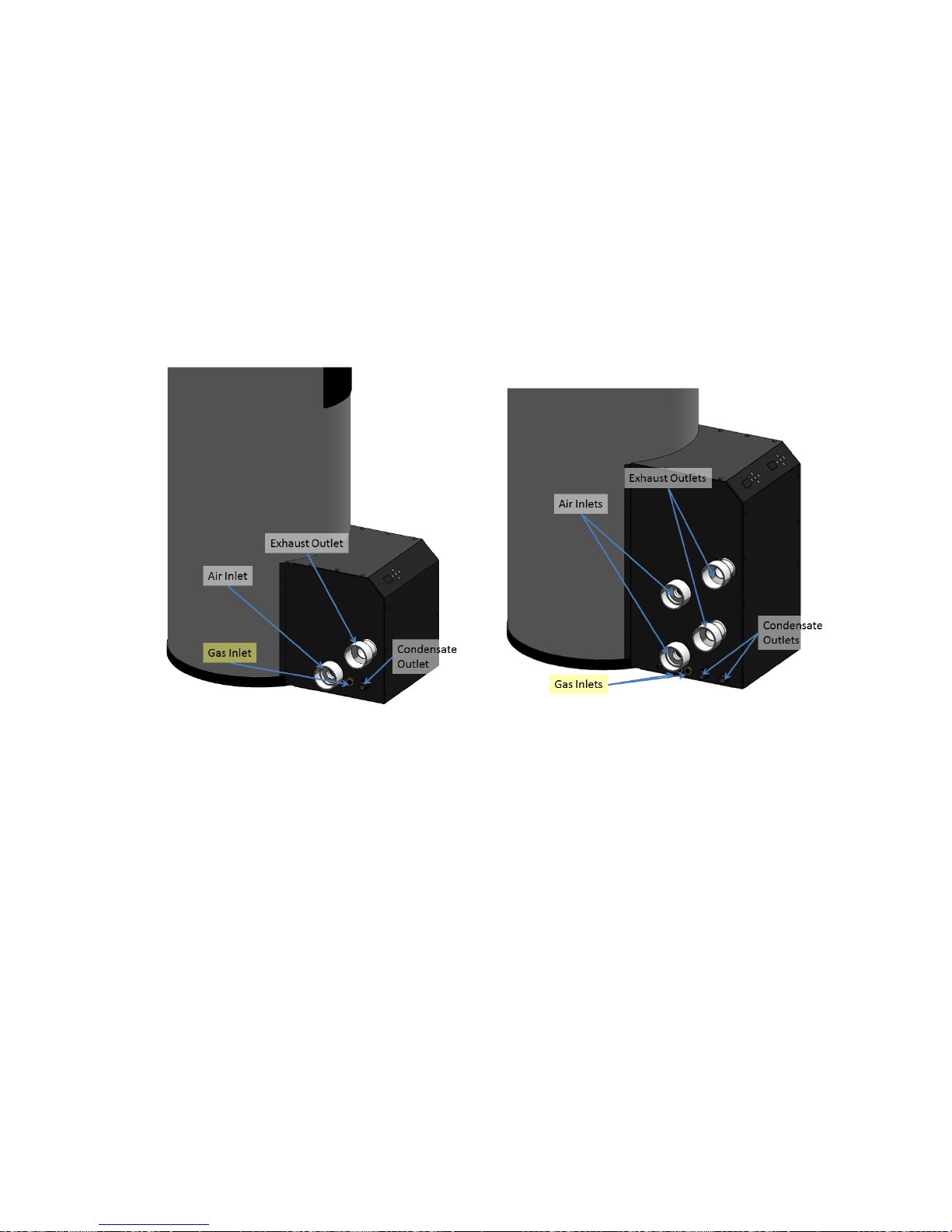
Figure 13 - Gas Inlet Location
Single Unit Heater on Left, Double Unit Heater on Right
Refer to the current National Fuel Gas Code ANSI Z223.1/NFPA 54 or CAN/CGA B149.1 installation
codes and local codes for gas piping requirements and sizing. Pipe size running to the unit depends on:
• Length of pipe
• Number of fittings
• Type of gas
• Maximum input requirement of all gas appliances
Page 26
26
Ensure that:
• The gas line connection to the water heater does not apply any weight to the gas valve. Hubbell
recommends using approved flexible gas piping (if acceptable by local codes) to connect the water
heater to the gas supply.
• You plan the installation so that the piping does not interfere with the vent pipe, or the removal of
the valve, burner, and serviceable components.
• The water heater shall be installed such that the gas ignition system components are protected from
water (dripping, spraying, rain, etc.) during installation and servicing.
• The gas piping is large enough for all the appliances. No appreciable drop in line pressure should
occur when any unit (or combination of units) lights or runs. Use common gas-line size practices.
• Always use a pipe-threading compound that is recommended for natural gas. Apply sparingly to all
male threads, starting at two threads from the end. Over doping or applying dope to the female end
can result in a blocked gas line.
• DO NOT TIGHTEN FITTING WITHOUT SUPPORTING THE GAS VALVE as damage to the gas
valve or combustion blower can occur.
• Install a manual “equipment shut-off valve” that is listed by a nationally-recognized testing lab.
• The gas line piping can safely be removed from the water heater for servicing by strategically
placing the gas line shutoff and union.
Page 27
27
• All gas piping, including gas components in the water heater, are checked for leaks using a “bubble
test” prior to operating the water heater.
WARNING:
• Strain on the gas valve and fittings may result in vibration, premature component failure and leakage
and may result in a fire, explosion, property damage, serious injury, or death.
• Flexible gas piping cannot be used within the water heater cabinet and cannot pass through the
cabinet wall, so rigid piping must be used. Failure to follow these instructions may result in fire,
property damage, serious injury, or death.
• Do not use an open flame to test for gas leaks. Failure to follow these instructions may result in fire,
property damage, serious injury, or death.
• When performing a pressure test on the gas line piping, be sure the water heater is disconnected or
isolated if the test pressure is expected to exceed ½ PSI (14”w.c.), as damage to the valve could
occur resulting in fire, property damage, serious injury, or death.
Gas Valve and Burner Set-up
WARNING: The gas valve must be set up by a licensed gas technician. Improper setup may result in
incorrect operation, damage to components or property, injury, or death.
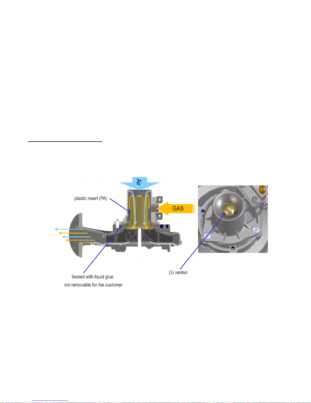
Figure 14 – Multiventuri Operating Principle
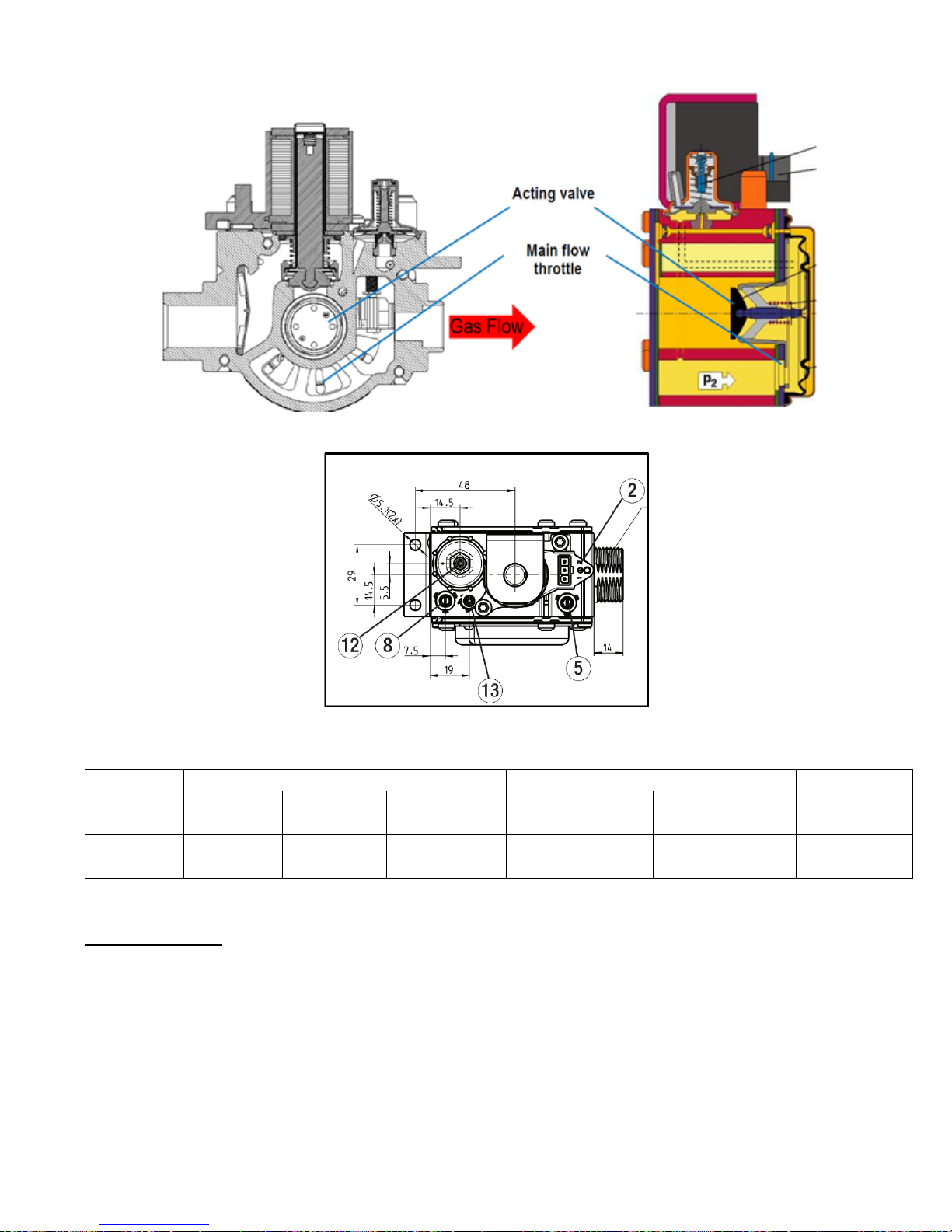
Figure 15 – Gas Valve Operating Principle
Page 28
28
Gas Type
Line Pressure (inches W.C.)
CO2 (%)
CO (ppm)
Max
Nominal
Min
Max
Min (3000 Fan
RPM)
Max (7500 Fan
RPM)
Natural
Gas
7.0
3.5
10.5
9.0%
9.5%
175
Figure 16 – Gas Valve Diagram
Table 7 - Gas Unit Values
Gas Line Pressure
The water heater gas valve is equipped with a line pressure test port. Use the following procedure to
measure the gas line pressure to the water heater to ensure it falls within the range given in Table 7 - Gas
Unit Values.
NOTICE: The inlet gas pressure must not exceed 10.5” H20.
1. Turn the supply of gas to the water heater off.
2. Open the bleed screw of the line pressure test port (item 8 in Figure 16 – Gas Valve Diagram)
approximately 1-1/2 turns. This port is directly connected to the gas line feeding the water heater.
Page 29
29
3. Force ¼” ID tubing over the housing of the line pressure test port; install the other end of the tubing
to an appropriate line pressure test gauge or manometer. Ensure both ends of the tubing make a tight
connection.
4. Open the supply of gas to the water heater and check for gas leaks.
5. Observe the line pressure under static conditions and compare it with the table above. The pressure
will be greatest under static conditions.
6. With all other gas appliances running, operate the burner to the maximum firing rate and compare it
to the table above. The pressure will be lowest during maximum flow of gas.
7. Adjust the gas line pressure to ensure the parameters in the table above are attained under all
conditions. If possible adjust the line pressure to the “Nominal/Desired” value listed in the table
above while the unit is operating at the maximum modulation rate.
8. Continue observing the gas line pressure until the completion of the combustion analyses in case
adjustments need to be made.
9. Upon the completion of the line pressure testing, return the bleed screw of the line pressure test port
to the closed position.
NOTICE: The line pressure is a function of the gas supply and is affected solely by field provided
parameters such as line size and regulator settings. Under no circumstances can the water heater gas valve
influence or be used to adjust the gas line pressure.
DANGER: Failure to close the bleed screw of the line pressure test port will cause a severe leakage of gas,
resulting in a fire or explosion causing property damage, serious injury, or death.
Gas Valve Calibration and Flue Analysis Procedure
WARNING: Failure to perform the flue gas analysis and adjustment detailed in this section may result in
erratic and unreliable burner operation, leading to reduced efficiency, increased fuel consumption, reduced
component life, heat exchanger combustion deposits, and general unsafe operation. Failure to follow these
instructions may result in serious injury or death.
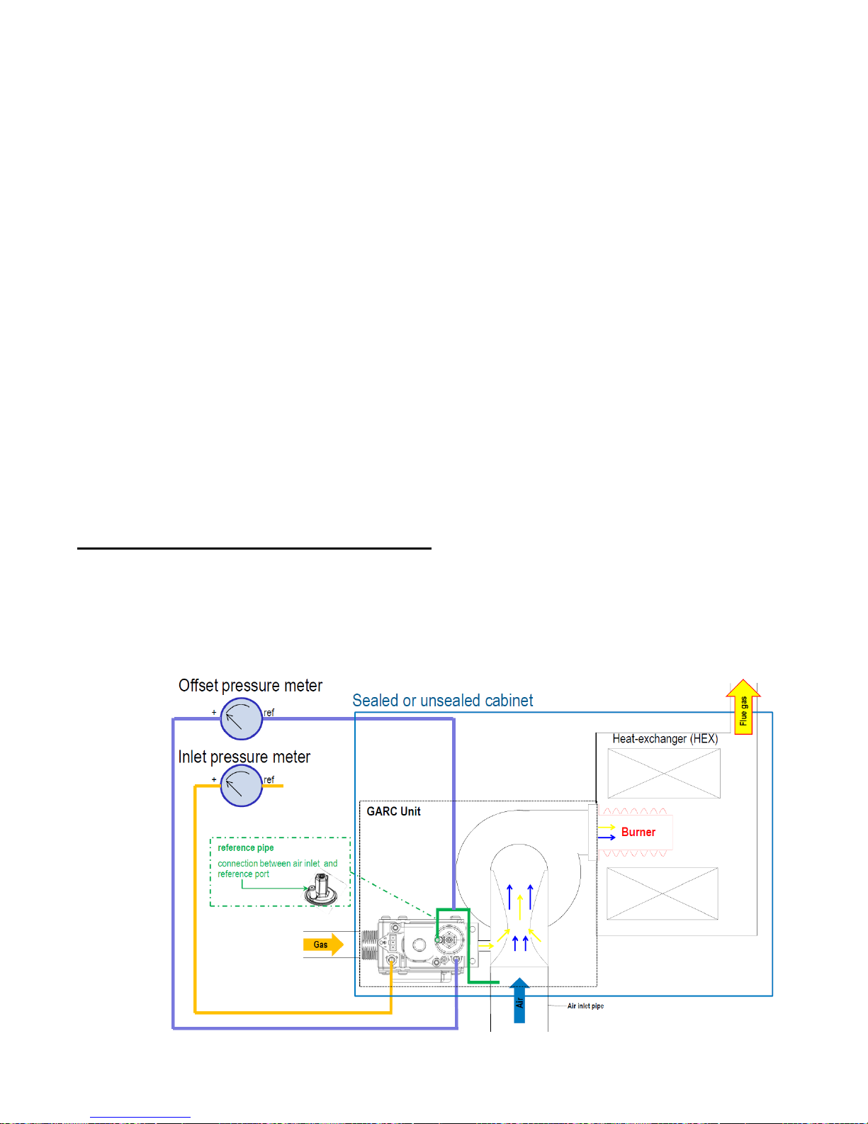
Figure 17 – Gas Valve Schematic
Page 30
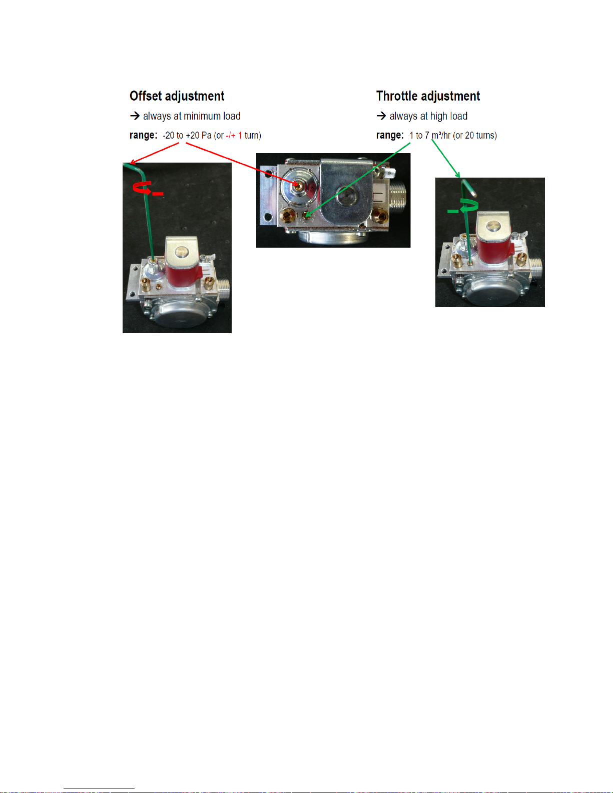
30
Figure 18 – Gas Valve Calibration
Figure 19 – Test Port Location
1. Read all safety instructions carefully.
2. Assemble and setup the appliance so that it is operational.
3. Connect all the proper combustion analysis equipment and insert combustion analyzer into
ventilation.
4. Run boiler at maximum speed (see Installer Menu).
5. Adjust gas flow until optimum CO2 level at maximum speed is achieved by turning throttle
adjustment screw (item 13 in Figure 16 – Gas Valve Diagram) clockwise to obtain lower C02 or
counterclockwise to obtain higher C02.
6. Run boiler at minimum speed (see Installer Menu).
7. Adjust gas flow until optimum CO2 level at minimum speed is achieved by offset adjustment screw
(item 12 in Figure 16 – Gas Valve Diagram) clockwise to obtain higher C02 or counterclockwise to
obtain lower C02.
8. Run boiler at maximum speed again and check CO2 level.
9. If CO2 level is ok skip next step.
10. If CO2 level is not ok, repeat steps 5-9.
NOTE: If you are installing a Dual Heat Exchanger unit, repeat all steps above exactly the same for the
second unit. These two units operate separately, and it is essential to make sure both sets of exchangers have
been set up properly.
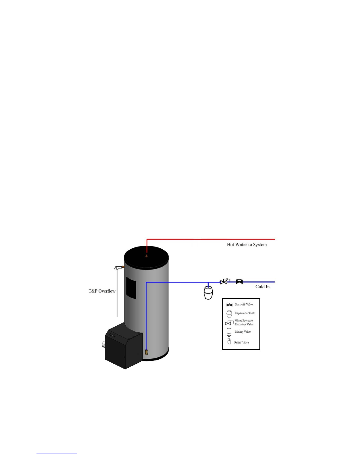
Water Piping Installation
1. Connect the cold water inlet and hot water outlet to the appropriate connections as shown; refer to
the drawing for location and sizes.
2. Install the combination temperature and pressure safety relief valve in the tapping provided. Note that
this is required by law for safety considerations.
Page 31
31
3. Install a relief valve overflow pipe to a nearby floor drain.
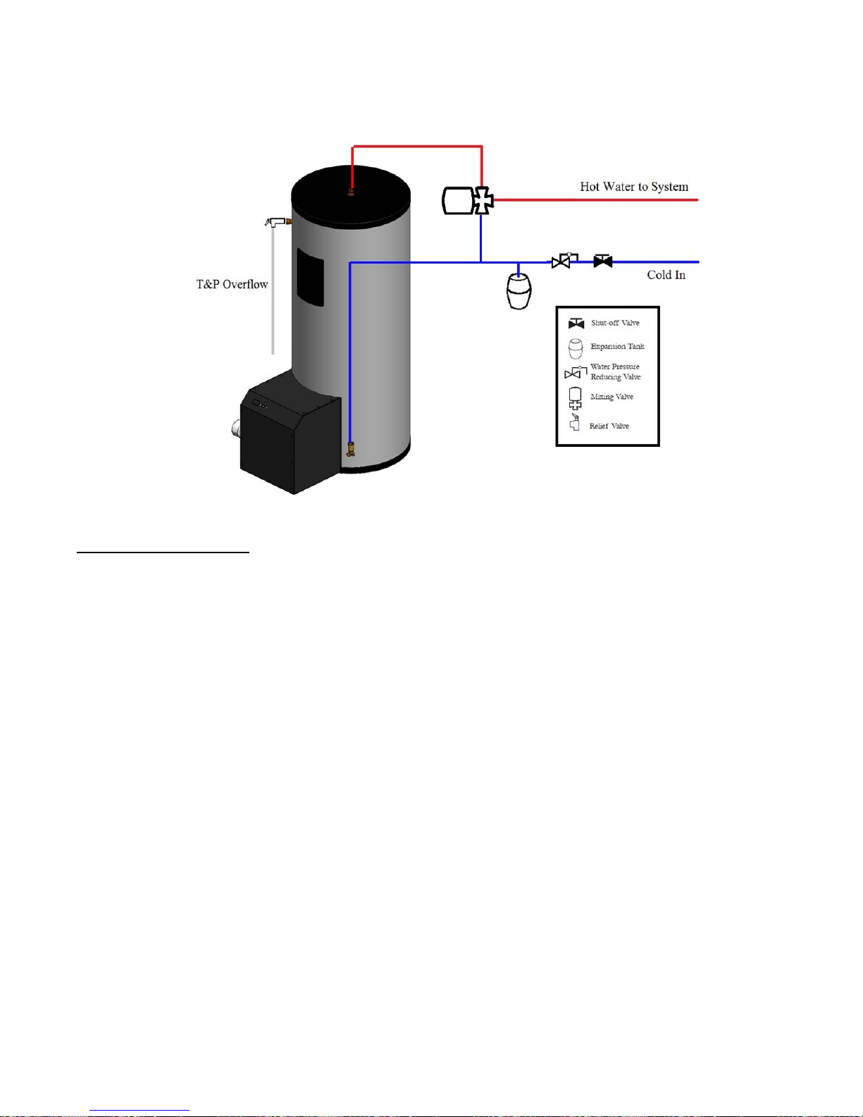
4. When the system requires water for space heating at temperatures higher than required for other
uses, a means such as a mixing valve shall be installed to temper the water for those uses in order to
reduce scald hazard potential. (See Figure 21 – Mixing Valve Water Piping Installation Diagram)
CAUTION: No valve of any type should be installed between the relief valve and tank or in the drain line.
NOTICE: The designed water supply temperature is to be below 160°F.
NOTICE: The water heater that will be used to supply potable water shall not be connected to any heating
system or component(s) previously used with a non-potable water heating appliance.
Space Heating Application
1. Water heaters for combination water/space heating shall not be used space-heating-only applications.
2. All piping and components connected to the water heater for the space heating application shall be
suitable for use with potable water.
3. Toxic chemicals, such as used for boiler treatment, shall not be introduced into the potable water
used for space heating.
4. To install piping for the space heating application, attach the space heating return and space heating
supply to the coil in the top of the tank.
Figure 20 – Water Piping Installation Diagram
Page 32
32
Figure 21 – Mixing Valve Water Piping Installation Diagram
Filling the Water Heater
1. Completely close the drain valve.
2. Open the highest hot water faucet to allow all air to escape from piping.
3. Open the valve to the cold water inlet and allow the heater and piping system to completely fill, as
indicated by a steady flow of water from the open faucet.
4. Close the faucets.
Electrical Installation
1. Power cord should be plugged directly into a proper 120V wall outlet. Power strips and extension cords
should not be used.
2. If equipped with elements, enter junction box with properly sized feeder leads. Note that overcurrent
circuit protection is required. For the standard model the overcurrent protection must be rated 25
amp minimum.
3. Connect these power leads to wires enclosed in junction box with wire nuts.
4. All other electrical connections are made at the factory; therefore, no other electrical connections are
necessary.
CAUTION: Label all wires prior to disconnection when servicing controls. Wiring errors can cause
improper and dangerous operation. Verify proper operation after servicing.
Final Checks
1. Check all connections for tightness.
2. Check for gas and water leaks.
Page 33

33
3. Ensure that all the above steps are completed.
Lighting the Water Heater
DANGER: Before Start-up refer to Mandatory Pre-commissioning Procedure for Plastic Venting in section
Mandatory Pre-commissioning Procedure for Plastic Venting (PVC or CPVC). Failure to follow these
instructions can result in explosion, injury, or death.
DANGER: Prior to turning the gas supply on and lighting the water heater, ensure all aspects of installation
are complete and in conformance with the instructions provided in this manual, including the Vent/Airintake, Condensate Drain, and System Water Piping. Failure to precisely follow these instructions will cause
fire or explosion resulting in property damage, serious injury, or death.
WARNING: Should overheating occur or the gas supply fails to shut off, turn off the manual gas control
valve to the water heater. Failure to follow instructions could result in explosion, causing property damage,
serious injury, or death.
Before lighting the heater at any point, ensure the following:
• The water heater is wired, and plumbed in accordance with this manual.
• The gas shut-off valve is turned on, and the gas system has been fully tested for leaks.
• The system is completely filled with water, and that ALL the air is purged out, and has been fully
tested for leaks.
WARNING: The initial lighting of the water heater must be performed by a licensed Gas Technician.
Failure to follow instructions may result in property damage, serious injury, or death.
DANGER: Allow primers/cements to cure for 8 hours prior to start-up. If curing time is less than 8 hours,
first perform steps 2 through 6 of section Mandatory Pre-commissioning Procedure for Plastic Venting
(PVC or CPVC). Failure to follow these instructions can result in explosion, serious injury, or death.
NOTICE: Should overheating occur or the gas supply fails to shut off, turn off the manual gas control valve
to the appliance.
Initial Start-Up
1. Insert 120V plug into outlet to power on gas unit. The water heater should run through a purge, and
combustion should occur. The control system has a built in ignition retry, allowing the system to try
at least three times before locking out.
2. With the unit operating at full capacity, verify that the gas line pressure is 3.5-13.5 inches W.C.
(.125-.5 psi) for natural gas.
3. Using an appropriate oxygen or carbon dioxide analyzer, take a sample of the flue gas. The sample
must fall within the acceptable ranges for carbon dioxide, which is 9.0% at low fire, and 9.5% at
high fire, for natural gas.
Perform at least three lights in succession to ensure proper operation.
4. After the three successive lights, switch gas inlet off, and allow the unit to cycle again. Ensure that it
tries to light three times and then shuts off.
NOTE: For the Dual Heat Exchanger unit, these steps should be repeated for the second heat exchanger
after testing the first using these steps; as each heat exchanger operates separately.
Page 34
34
WARNING: If the unit fails to light consistently and smoothly, contact Hubbell for technical assistance at
1-203-378-2659. Never allow the water heater to operate if the ignition or operation of the burner is rough
or erratic. Failure to follow these instructions may result in serious injury or death.
Turning Off the Water Heater
1. Set the thermostat to the lowest setting and then turn off all power to the water heater.
2. Turn the gas shut-off valve to the off position.
Turning On the Water Heater
1. Stop and read these instructions very carefully.
2. This water heater does not have a pilot. It is equipped with an ignition device that automatically
lights the burner. Do not try to light the burner by hand.
3. Turn the gas shut-off valve to the off position and then remove the front cover.
4. Wait five minutes to clear out any gas. Then check for gas, including near the floor. If you smell gas,
STOP and see the directions in the front of this manual. If you do not detect any gas, proceed.
5. Turn the gas shut-off valve to the on position, wait an additional five minutes, and check for gas.
6. Replace the front cover.
7. Set the thermostat to the desired setting, and then turn on all power to the water heater.
8. The ignition sequence is automatic and combustion will occur after a brief fan purge. Ignition will
retry 3 times.
9. If ignition does not occur, turn off the gas and electricity to the water heater and contact a
professional service technician or gas supplier.
10. After the water is heated for the first time, monitor the water temperature as described in the
Scheduled Maintenance section.
3.0 CONTROLLER OPERATION
LCD Display
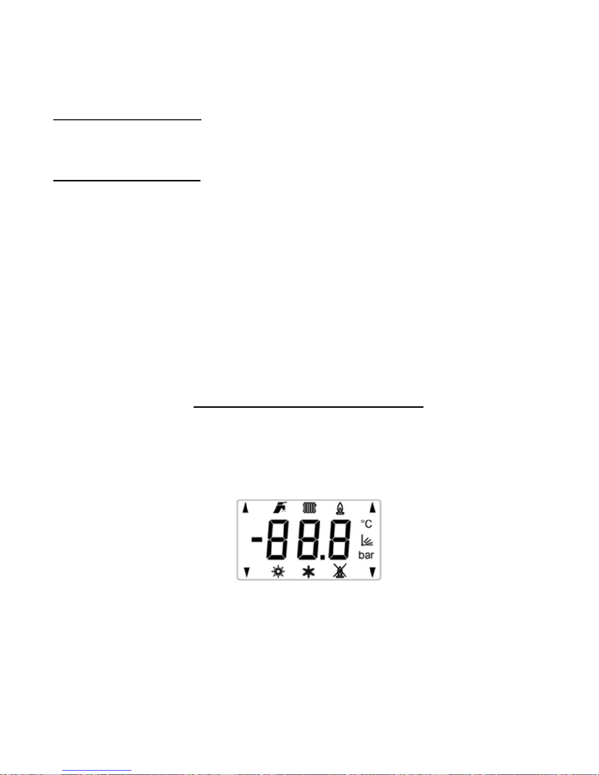
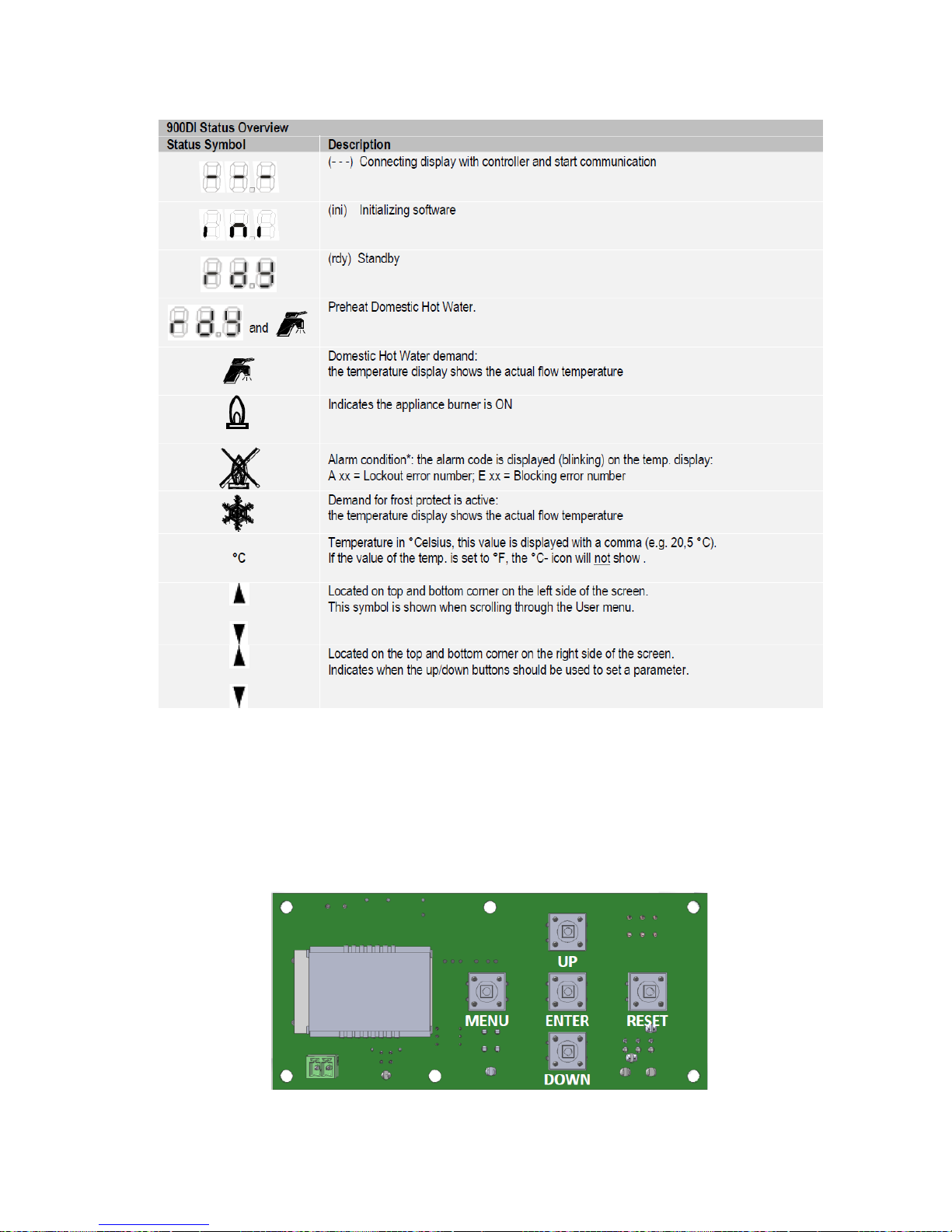
The display module contains 13 symbols and three 7-segment blocks (with a minus-sign and a dot, as shown in
the figure 1).
Figure 22 - LCD Symbols
The table below describes the function per symbol.
Page 35
35
Table 8 - Status Symbols and Their Meanings
Button Layout
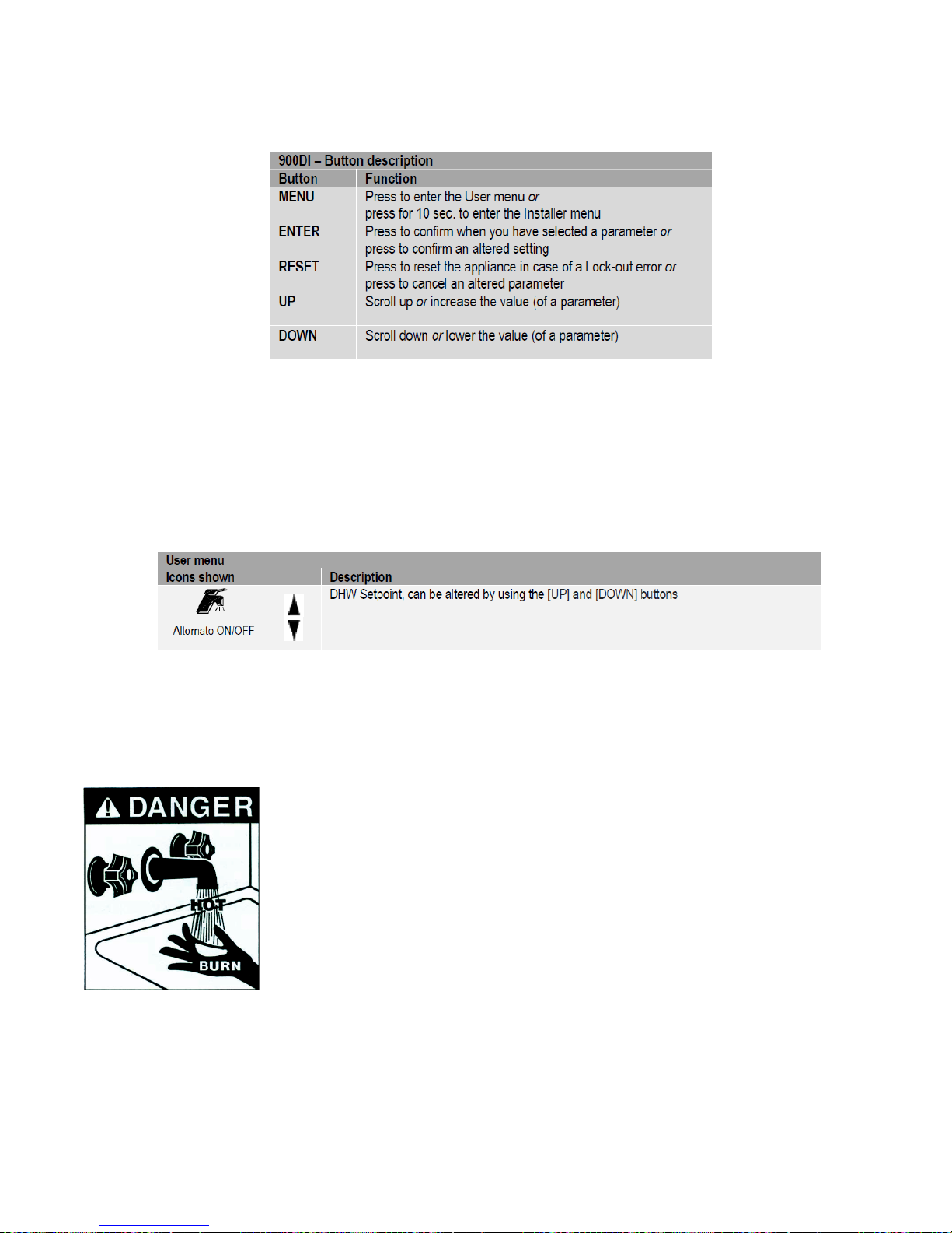
5 different buttons are present on the 900DI LCD Display for operating the module, which are positioned the
right side of the display. Figure 2 shows the location of the buttons.
Figure 23 - Lay-out with Push Buttons
The table below describes the button functions.
Page 36
36
Table 9 - Button Functions
Temperature Adjustments via Status Overview
Set DHW set point directly via status overview
The DHW set point can be directly adjusted in the Status overview. In that case, the following icons are shown,
including the set point temperature that is being altered.
Table 10 - Important Icon Descriptions
When the DHW set point is being directly adjusted via the Status overview and is set below
DHW_Setpoint_Min, the display will show “OFF” (blinking). This means that the appliance is OFF and will not
respond to any DHW demand anymore (and that you cannot lower the value any further).
DANGER: When altering the set temperature of the appliance:
• Water temperature over 125°F can cause severe burns instantly or death from
scalds.
• Children, disabled and elderly are at the highest risk of being scalded.
• See instruction manual before setting temperature at the water heater.
• Feel water before bathing or showering.
• Temperature limiting valves are available, see manual.
The temperature of the water in the heater is regulated by an adjustable, automatic,
temperature control which uses surface mounted thermistors located behind the
jacket access panels. These automatic controls are set at the factory to maintain a
water temperature of 120°F. Although these controls are designed to industry
standards, they can fail to control temperature properly without any notice, and therefore should be tested
periodically for your protection.
To perform the test: Turn on the hot water faucet and measure the maximum temperature with an accurate
thermometer. If the temperature is above the safe limits for your circumstances call a service technician to
adjust or replace the control.
Page 37
37
DANGER: IF YOU DISCOVER EXTREME HOT WATER COMING FROM THE FAUCET,
IMMEDIATELY SHUT OFF THE ELECTRICITY AND GAS AT THE MAIN SWITCH AND
CALL COMPETENT SERVICE PERSONNEL. ANY OVERHEATED WATER HEATER IS A
POTENTIAL HAZARD TO LIFE AND PROPERTY. DO NOT OPERATE UNTIL THE SOURCE
OF THE PROBLEM HAS BEEN DETERMINED AND ELIMINATED.
Showing Errors on the Status Overview
In case of a Warning or Error/Alarm condition, the Blocking (‘E’), Locking (‘A’), or Attenuations (‘n’) error
number will be constantly displayed on screen (blinking). The User menu will be inaccessible at this time.
When this situation occurs, the Locking error (L) can be reset by pressing [RESET].
If any errors appear on your controller during operation, reference the error messages section of
Troubleshooting or call a qualified technician to examine your water heater.
User Menu
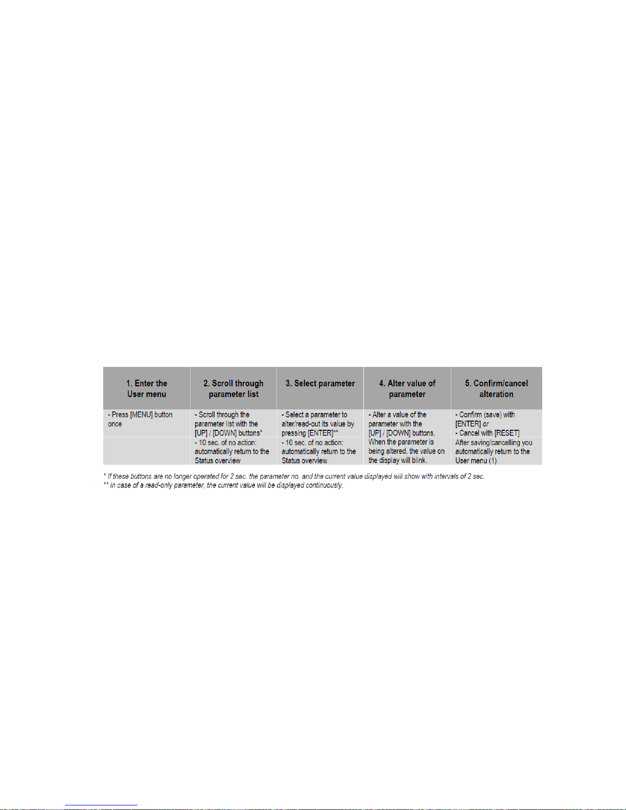
Enter the User view menu by pressing the [MENU] button once. This menu can be used to look at the values of
a selection of parameters (read-only) or to view the sensor temperatures. The table below shows how to
enter/operate the User menu in some simple steps:
Table 11 - User Menu Guide
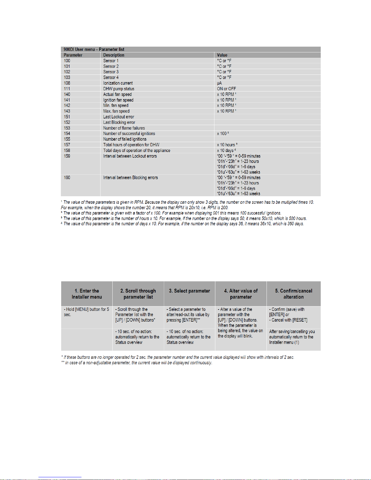
The following table describes the parameters in the User menu, which are all read-only:
Page 38
38
Table 12 - Parameter List and Descriptions
Installer Menu
The table below schematically shows how to enter/operate the Installer menu in some simple steps:
Table 13 - Installer Menu Guide
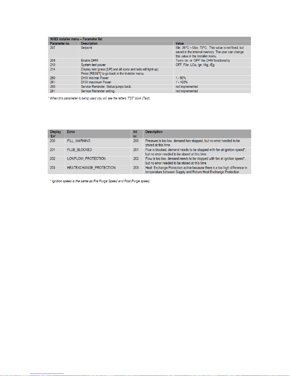
The following table shows the available parameters in the Installer menu.
Page 39
39
Warnings
Table 14 - Installer Menu Parameter List
Table 15 - Descriptions of Errors
If any errors appear on your controller during operation, reference the error messages section of
Troubleshooting or call a qualified technician to examine your water heater.
Page 40

40
4.0 SCHEDULED MAINTENANCE
WARNING / CAUTION
Before performing any maintenance procedure, make certain the power supply is OFF and cannot accidentally
be turned on.
Freezing
The tank should be fully drained in the event the electricity has been turned off and if there is danger of
freezing.
Manual Inspection
1. Monitor temperature as follows:
a. Let water heater completely heat to the designated set point.
b. When heated (that is, when unit stops running).
c. Compare water temperature of drawn water to the temperature set point of the controller. Normal
variation between the two points is approximately + 5°F.
d. If the two readings do not coincide within acceptable tolerances and verification has been made of
the accuracy of the temperature-reading gauge, replace the controller.
2. Lift test lever on relief valve and let water run through valve for a period of approximately 10 seconds.
This will help flush away any sediment that might build up in water passageways.
3. Inspect heat exchanger and flange for leakage as follows:
a. Shut off power supply, gas supply, and remove housing cover.
b. Visually inspect for evidence of leakage.
4. Check that the tank lights smoothly and consistently, that the combustion fan is noise and vibration
free, and that condensate is able to exit the unit freely and no sediment has built up within.
a. Clean the burner of any residue to prevent any unwanted objects from ending up in the burner.
b. If the unit does not run smoothly, turn off the power and gas, and call a qualified licensed
technician.
5. Inspect ventilation to be sure that there is no obstruction, leak, or damage that would cause a backup
or leak of gas.
6. Check for loose electrical connections. Tighten as necessary.
7. Flush tank as follows
a. Shut off power supply and gas supply.
b. Close valve on cold water inlet piping.
c. Open valve on drain piping.
d. Open hot out fixture to let in air.
e. Allow tank to empty.
f. Close drain valve.
g. Open cold water valve.
h. Fill tank until water comes out of hot out fixture, and keep open until there is no more air coming
out.
i. Close hot out fixture.
j. Turn power supply and gas ON.
Page 41
41
5.0 TROUBLESHOOTING
Symptom
Probable Cause
Corrective Action / Remedy
No hot water
Circuit breaker tripped at source
Reset circuit breaker.
High limit switch tripped
Reset high limit switch.
Loose wires
Tighten wire connections.
Low line voltage
Have source electrical system checked by
an electrician.
Faulty controller
If controller display is not lit and power is
available at the controller, check wire
connections then replace controller.
Faulty temperature sensor(s) /
controller
If the temperature indicated by the
controller when set to display the actual
temperature does not match the actual
temperature of the water (within ±5°F),
replace controller and/or temperature
sensors.
Controller Error
See controller error codes below.
Incorrect set point (too low)
Increase the set point.
Symptom
Probable Cause
Corrective Action / Remedy
Water temperature
below settings at all
times
Faulty temperature sensor(s) /
controller
If the temperature indicated by the
controller when set to display the actual
temperature does not match the actual
temperature of the water (within ±5°F),
replace controller and/or temperature
sensors.
Low line voltage
Have source electrical system checked by
an electrician.
Incorrect set point (too low)
Increase the set point.
Heater improperly sized
Verify heater is properly sized for the flow
rate and temperature rise of your system.
Replace elements with proper size as
necessary.
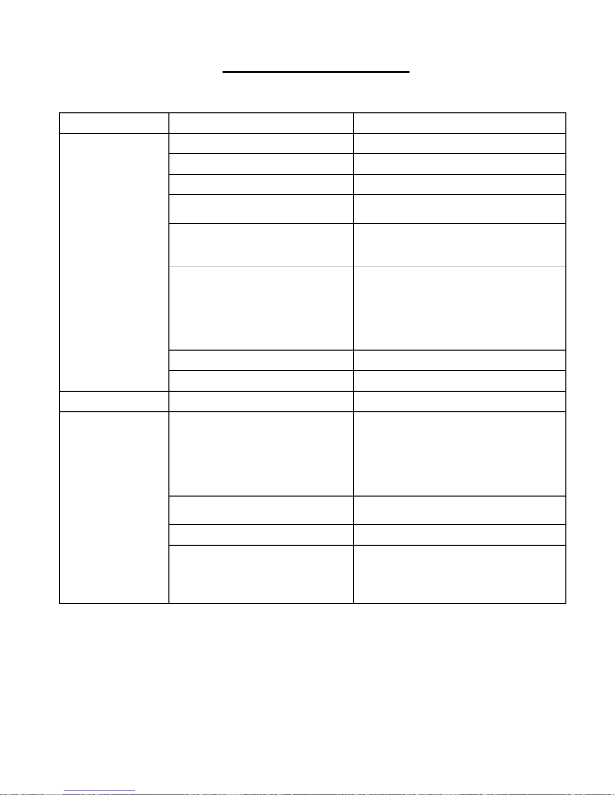
Table 16 - Troubleshooting for Potential Issues
Page 42
42
Relief valve
discharges
continuously
Excessive temperature or pressure in
tank
Temperature and pressure relief valves are
designed to operate if the water
temperature exceeds 210°F or tank
pressure exceeds the pressure rating of the
safety relief valve. If trouble is excessive
temperature, then controller is not shutting
off at the set point and controller must be
replaced. If pressure, likely cause is
thermal expansion. Contact plumber and
consider installing a thermal expansion
tank.
Controller Error Messages and Procedures
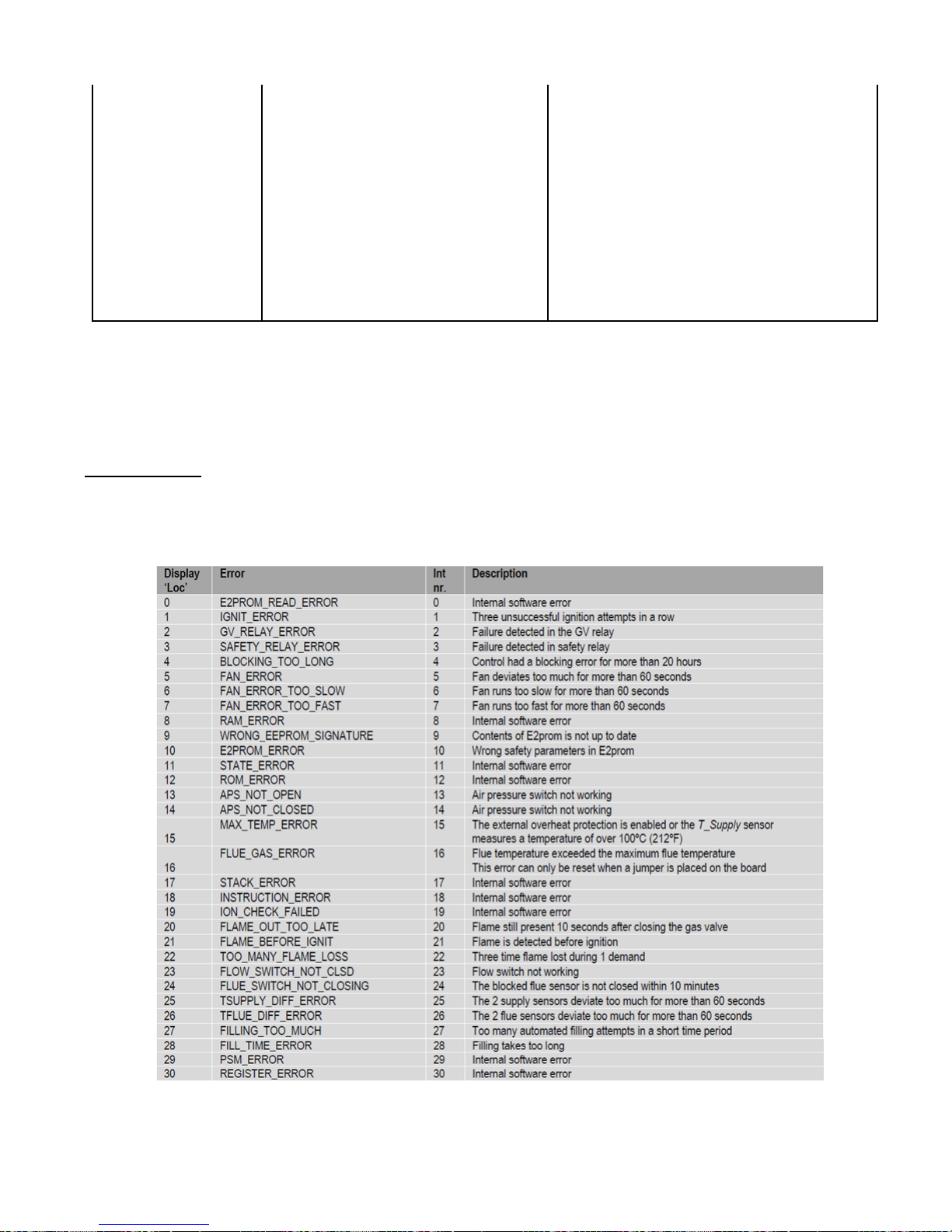
Lockout Codes
Errors are indicated starting with an ‘A’:
Table 17 - Lockout Error Codes
NOTICE: A24 is an error for either a blocked flue or a blocked condensate and requires inspection of both.
Page 43
43
Blocking Errors
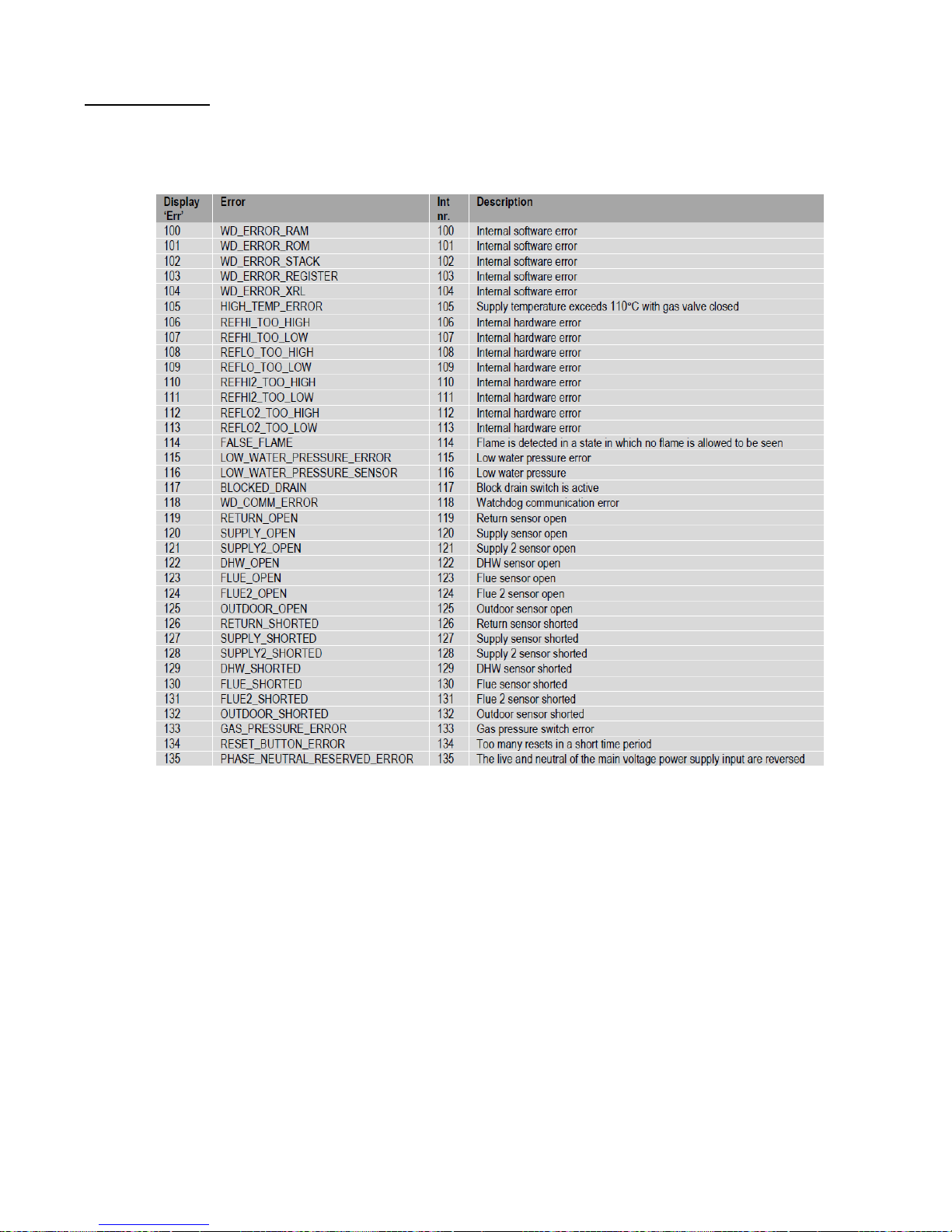
The following errors are related to the general control functions. Errors are indicated starting with an ‘E’:
Table 18 - Blocking Error Codes
Page 44

44
6.0 MAINTENANCE & SERVICING
WARNING / CAUTION
Before servicing or replacing any part make sure to turn the power supply switch to the OFF position.
Surface Temperature Hi-Limit Cutout Switch
1. Disconnect power from unit.
2. Remove upper access cover.
3. Disconnect the wires from the four terminals.
4. Remove hi-limit switch.
5. Install new high limit switch.
6. Rewire hi-limit switch according to wiring diagram.
7. Reinstall access cover.
Removing the Condensate Outlet
1. Disconnect power from the unit.
2. Shut gas valves to stop incoming gas supply.
3. Open the gas unit housing.
4. Undo the PVC union near the left side of the enclosure.
5. Disconnect hose clamps on the condensate drain from PVC side outlet elbow.
6. Remove the two nuts holding the condensate box to the heat exchanger.
7. Remove PVC exhaust/condensate outlet assembly.
Removing the Fan Assembly
1. Disconnect power from the unit.
2. Shut gas valves to stop incoming gas supply.
3. Open the gas unit housing.
4. Remove hose clamp on air inlet on fan side.
5. Disconnect air hose.
6. Remove gas line from gas valve.
7. Remove Condensate Outlet- see above.
8. Remove the 4 bolts and nuts from the fan connector.
9. Remove fan assembly.
Heat Exchanger
1. Disconnect power from the unit.
2. Shut gas valves to stop incoming gas supply.
3. Shut off incoming water supply.
4. Attach hose to a drain connection.
5. Open hot water faucet to allow tank to drain completely.
6. Open the gas unit housing.
Page 45

45
7. Remove the condensate outlet. See above.
8. Remove the fan assembly. See above.
9. Disconnect wires from the spark electrode and ionization probe.
10. Remove the 8 bolts and nuts.
11. Remove the heat exchanger and replace with a new one.
12. Ensure both O-rings are placed correctly.
13. Replace all nuts and bolts.
14. Replace condensate box.
15. Replace fan assembly.
16. Replace wires.
17. Fill the tank and check around for any leaks.
18. Reopen gas valves and turn on power.
Relief Valve
1. Disconnect power from unit.
2. Shut off incoming water supply.
3. Lift test lever on relief valve to relieve pressure in tank.
4. Disconnect overflow piping.
5. Unscrew relief valve, remove assembly and replace with new one.
6. Connect overflow piping.
7. Turn on incoming water supply and check for leaks.
Heating Element (If Equipped)
1. Disconnect power from unit.
2. Shut off incoming water supply.
3. Attach hose to drain connection.
4. Open hot water faucet to allow tank to drain completely.
5. Remove upper and/or lower access cover, as applicable.
6. Disconnect the wires from the heating element terminals.
7. Remove the element from the tank.
8. Install new gasket and new heating element.
9. Rewire element according to wiring diagram.
10. Fill tank and check around gasket for any leaks. Tighten nuts as required.
11. Reinstall access cover(s).
Page 46
46
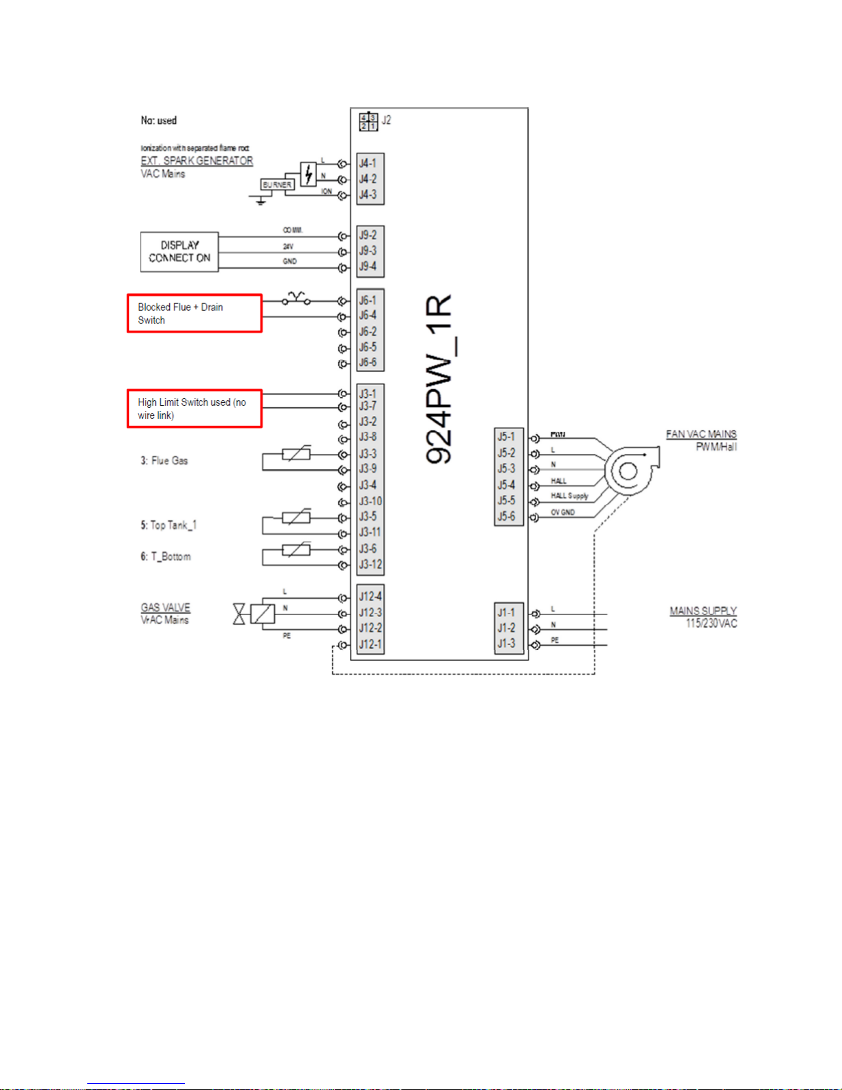
Figure 24 – Wiring Diagram of Burner Control
Page 47
47
7.0 REPLACEMENT OF PARTS
HUBBELL
DRAWING
NUMBER
PART NUMBER
DESCRIPTION
QTY.
55k
QTY.
110k
Heat Exchanger
1
2
V24S0021
GA0101625
Mounting Plate O Ring
1
2
V24S0022
GA0101675
Stretched Mounting Plate O Ring
1
2
V24S0023
FA200102528075
1/4"-28 x 3/4" UNF Stud
4 8 V24S0023
FA050102528125
1/4"-28 x 1 1/4" Bolt
6
12
FA2001025200
1/4"-28 x 2" Stud
2
4
V24S0024
FA0401025000
1/4" Washer
10
20
FA1101025000
1/4" Lock Washer
8
16
V24S0025
FA030102528
1/4" (28) UNF Nut
18
36
V24S0031
GP3810000000000
Mounting Plate
1
2
GP2000000000000
Display
1
2
GP2100000000000
Burner Control
1 2
GP2300000000000
Ignition Transformer
1
2
MS051042000001
Air Pressure Switch
1
2
V24S0080
GP150253155817
Fan Coupler Type
1 2 V24S0041
GP160110047323
Burner
1
2
GP1900000000000
Fan
1
2
GP2403057200000
Venturi
1
2
GP2500000000000
Gas Valve
1
2
GP2200005000000
Flange Kit 1/2"NPT Straight
1 2 V24S0042
GP170000383840
Spark Electrode
1
2
V24S0043
GP180000385140
Ionization Probe
1
2
V24S0036
GA1003374
Electrode Seal
2 4 V24S0047
GA11043140
Fan Gasket
1
2
V24S0048
GA12054726
Fan Coupler Gasket
1
2
V24S0049
GA13051063
Burner Gasket
1
2
V24S0050
GA1406449
Insulation Pad
1
2
V24S0051
GA1507827
Exhaust Seal
2 4 V24S0044
FA18011032075
#10-32 x 3/4" Allen Head Bolt (Fan)
4
8
V24S0045
FA03011032000
#10-32 Nut (Fan)
4
8
V24S0046
FA04010010000
#10 Washer (Fan)
8
16
FA0403008000
#8 Internal Thread Washer (Burner)
4
8
FA1803832025
#8-32 x 1/4"Allen Head Bolt (Burner)
4
8
V24S0070
FA1801832375
#8-32 x 3/8" Allen Head Bolt (Spark/Ionization)
4
8
V24S0052
FA1607375000
Cable Gland
1
1
For replacement parts, please reference the list below. All the following parts can be supplied by Hubbell
Heater Company.
Page 48
48
FA0304375000
Cable Gland Nut
1
1
V24S0053
FA1708075000
Condensate Connector
1 2 V24S0074
FA03083015000
Condensate Nut
1
2
V24S0054
GP2604005000000
1/2" FPT Brass Term Bolt
1
2
V24S0055
GP2701005018000
1/2" Gas Line S.S.
1
2
V24A0020
PVC Exhaust Assembly
1
1
PVC Exhaust Assembly (Upper)
- 1
PL041471606
Flue Plug
1
V24S0065
GA16071428
O-Ring SSL 35 x 2.0
1
MS050000000029
1/2" NPT Float Switch
1 2
FT36100125000
1/8" NPT Barbed Hose Fitting
1
2
V24S0071
GP3508002120000
Condensate Pipe with Loop
1
2
GP3608002100000
Condensate Joining Sleeve
2
4
FA080820000
Condensate Hose Clamp
4
8
V24S0072
GP3709019700000
Air Duct
1 2 V24S0075
FA0803200000
Air Duct Hose Clamp
2
4
FA0301A24000
#10-24 Nut (Controller/Igniter)
7
14
FA0301832000
#8-32 Nut (Display)
8
16
FA210420000
Snap Rivet (Mounting Plate)
12
12
Page 49

49
WARRANTY
Tank/Heat Exchanger Replacement Policy
One Year Limited Parts Warranty
Hubbell Heater Company, (hereinafter called the company) offers the following Limited Warranty and Tank Replacement Policy to the
purchaser/owner of this stone-lined residential water heater.
This Limited Warranty and Tank Replacement Policy is not transferable beyond the original purchaser/owner and is not valid if tank is
removed from initial installation site. The Company reserves the right to require proof of purchase as a condition of this warranty.
Excludes any implied warranty of merchantability or fitness for any particular purpose.
LIMITED WARRANTY
COMPONENT REPLACEMENT POLICY
DURATION: The warranty is effective for (1) year beginning with the date of original purchase.
COVERAGE: The warranty covers any component part of the water heater proven to be defective in workmanship or material.
Recovery under the terms of this agreement is subject to prior approval by the company.
COMPANY OBLIGATION: Repair or replacement is at the option of the company and constitutes the fulfillment of ALL obligations
of the Company hereunder.
LIMITATION: All repairs or replacements will be made F.O.B. the company. The purchaser must pay for transportation service,
labor, installation, administrative fees or other costs involving the repair or replacement of such component parts.
YOUR ACTION: When you discover a defect, immediately notify your local representative from whom the heater was purchased. If
you cannot locate the representative, contact the Company.
TANK REPLACEMENT POLICY
DURATION: (7) years from the date of original purchase. Exception: (10) years for ASME Stamped Vessels, see Limitations below.
COVERAGE: Replacement policy covers only the storage tank for leaks caused by the corrosive effects of the water under normal and
proper use. Recovery under the terms of this agreement is subject to prior approval by the company. The tank replacement policy
excludes any performance warranty implied or specific of merchantability and fitness for its intended use.
COMPANY OBLIGATION: Repair of the original tank or replacement of the entire heater with a new comparable model is at the
option of the Company and constitutes the fulfillment of all the obligations of the Company hereunder. In replacing or repairing the
water heater, the Company reserves the right to make such changes in details of design, construction or material as shall in their
judgment constitute an improvement of former practices.
REPLACEMENT: When a replacement is made under the terms of this policy, the replacement unit will have a policy of replacement
only for the remaining time under the original policy. The Company reserves the right to require return of the defective unit at the
expense of the purchaser.
LIMITATION: All repairs or replacements will be made F.O.B. the Company. The purchaser must pay for transportation, service, labor
installation, administrative fees or other costs involving the repair or replacement of such part
YOUR ACTION: When you discover a defect, immediately notify the representative from whom the heater was purchased. If you
cannot locate the representative, contact the Company
HEAT EXCHANGER REPLACEMENT POLICY
DURATION: (5) years from the date of original purchase, see Limitations below.
COVERAGE: Replacement policy covers only the heat exchanger for leaks caused by the corrosive effects of the water under normal
and proper use. Recovery under the terms of this agreement is subject to prior approval by the company. The tank replacement policy
excludes any performance warranty implied or specific of merchantability and fitness for its intended use.
COMPANY OBLIGATION: Repair of the original heat exchanger or replacement of the entire heat exchanger with a new comparable
model is at the option of the Company and constitutes the fulfillment of all the obligations of the Company hereunder. In replacing or
repairing the heat exchanger, the Company reserves the right to make such changes in details of design, construction or material as shall
in their judgment constitute an improvement of former practices.
REPLACEMENT: When a replacement is made under the terms of this policy, the replacement unit will have a policy of replacement
only for the remaining time under the original policy. The Company reserves the right to require return of the defective unit at the
expense of the purchaser.
LIMITATION: All repairs or replacements will be made F.O.B. the Company. The purchaser must pay for transportation, service, labor
installation, administrative fees or other costs involving the repair or replacement of such part
YOUR ACTION: When you discover a defect, immediately notify the representative from whom the heater was purchased. If you
cannot locate the representative, contact the Company
Page 50

50
EXCLUSIONS AND LIMITATIONS
Limited Warranty and Tank/Heat Exchanger Replacement Policy are valid only if you comply with the following conditions and
limitations:
1. The water heater must be correctly installed according to the installation manual provided with the unit and all applicable local
and national codes.
2. The unit must be operated within the factory calibrated temperature limits and water pressure not exceeding 150 psi.
3. Any failure or malfunction that results from improper or negligent operation, accident, abuse (including freezing), misuse, unauthorized
alteration or improper maintenance is specifically excluded.
4. Any failure or malfunction that results from failure to keep the tank full of potable water, free to circulate at all times, and free of
damaging water sediment or scale deposits, is specifically excluded. In areas where adverse water conditions are suspected (i.e.
calcium and other minerals), it is essential that the water be tested and appropriate action be taken to prevent damage to the water
heater.
5. This Limited Warranty and Tank Replacement Policy specifically exclude any implied warranty of merchantability or of fitness
for any particular purpose, as well as any performance warranty.
IN NO EVENT SHALL THE COMPANY BE LIABLE FOR ANY INCIDENTAL OR CONSEQUENTIAL DAMAGES
WHATSOEVER. Some states do not allow the exclusion or limitation of implied warranties or of liability for incidental or
consequential damages, so the above limitation(s) or exclusion(s) may not apply to you.
Page 51

51
List of Figures
Figure 1 - Tank Assembly (55k Btu Unit on top, 110k Unit on bottom) .......................................................... 8
Figure 2 - Ventilation Connections ................................................................................................................. 13
Figure 3 - Two Pipe Termination (Sidewall) ................................................................................................... 17
Figure 4 - Two Pipe Low Profile Termination (Sidewall) .............................................................................. 18
Figure 5 - Two Pipe Concentric Termination (Sidewall) ................................................................................ 18
Figure 6 - Two Pipe Termination (Roof) ......................................................................................................... 19
Figure 7 - Two Pipe Concentric Termination (Roof) ...................................................................................... 19
Figure 8 –Venting Below Grade ...................................................................................................................... 21
Figure 9 - Outdoor Venting Guidelines ........................................................................................................... 21
Figure 10 – Existing Chimney Chase Way ..................................................................................................... 21
Figure 11 - Basic Ventilation Layout .............................................................................................................. 23
Figure 12 - Condensate Outlet Location .......................................................................................................... 24
Figure 13 - Gas Inlet Location ......................................................................................................................... 25
Figure 14 – Multiventuri Operating Principle ................................................................................................. 27
Figure 15 – Gas Valve Operating Principle ..................................................................................................... 27
Figure 16 – Gas Valve Diagram ...................................................................................................................... 28
Figure 17 – Gas Valve Schematic ................................................................................................................... 29
Figure 18 – Gas Valve Calibration .................................................................................................................. 30
Figure 19 – Test Port Location ........................................................................................................................ 30
Figure 20 – Water Piping Installation Diagram ............................................................................................... 31
Figure 21 – Mixing Valve Water Piping Installation Diagram ....................................................................... 32
Figure 22 - LCD Symbols ............................................................................................................................... 34
Figure 23 - Lay-out with Push Buttons ........................................................................................................... 35
Figure 24 – Wiring Diagram of Burner Control .............................................................................................. 46
Table 1- Model Specific Dimensional Data ...................................................................................................... 9
Table 2 - Possible Ventilation Contaminants .................................................................................................. 14
Table 3 - Vent/Air-inlet Pipe Materials ........................................................................................................... 15
Table 4 - Vent and Air-inlet Pipe Length Determination ................................................................................ 15
Table 5 - Vent and Air-inlet Pipe Length Determination (Common Vented Double Unit) ............................ 16
Table 6 - Vent and Air-intake Termination Clearances .................................................................................. 22
Table 7 - Gas Unit Values ............................................................................................................................... 28
Table 8 - Status Symbols and Their Meanings ................................................................................................ 35
Table 9 - Button Functions .............................................................................................................................. 36
Table 10 - Important Icon Descriptions ........................................................................................................... 36
Table 11 - User Menu Guide ........................................................................................................................... 37
Table 12 - Parameter List and Descriptions .................................................................................................... 38
Table 13 - Installer Menu Guide ...................................................................................................................... 38
Table 14 - Installer Menu Parameter List ........................................................................................................ 39
Table 15 - Descriptions of Errors .................................................................................................................... 39
List of Tables
Page 52

52
Table 16 - Troubleshooting for Potential Issues .............................................................................................. 41
Table 17 - Lockout Error Codes ...................................................................................................................... 42
Table 18 - Blocking Error Codes ..................................................................................................................... 43
 Loading...