

Page 1
MOUNTING
PAGE 3
FIGURE 7
FIGURA 7
FIGURE 8
FIGURA 8
PAGE 3
PAGE 3
PAGE 3
framework.
is the same thread that is on the T-SLOT fastener. The NLCA1
can be used for mounting single fixtures.
different configurations.
PAGE 3
FIGURE 7
FIGURA 7
T-SLOT
FASTENER
NLCA1
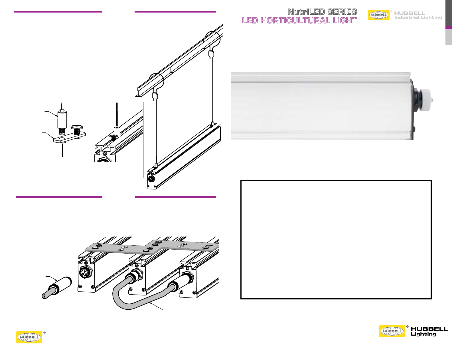
SECURING THE FIXTURE (See Figure 7 and Figure 8):
1. Aircraft cable can be used to secure the fixture to a TRUSS or
framework.
2. NLCA1 is a single point cable with a ¼-20 threaded stud. This
is the same thread that is on the T-SLOT fastener. The NLCA1
can be used for mounting single fixtures.
3. NLCA2 is a double point “Y” cable system that can be used for
different configurations.
FIGURE 8
FIGURA 8
MORE than 16 fixtures on one power drop.
SECURING THE FIXTURE (See Figure 7 and Figure 8):
1. Aircraft cable can be used to secure the fixture to a TRUSS or
framework.
2. NLCA1 is a single point cable with a ¼-20 threaded stud. This
is the same thread that is on the T-SLOT fastener. The NLCA1
can be used for mounting single fixtures.
3. NLCA2 is a double point “Y” cable system that can be used for
different configurations.
NLCA1
T-SLOT
FASTENER
NutriLED SERIES
LED HORTICULTURAL LIGHT
FIGURE 7
FIGURA 7
OPERATION
POWERING THE FIXTURE(S) (See Figure 9):
1. Attach power cord to POWER IN panel connector.
2. An INTERCONNECT cord can be used to power multiple
fixtures or “DAISY CHAIN” fixtures together. Connect NO
POWER CORD
FIGURE 8
FIGURA 8
INTERCONNECT
CORD
WARNINGS
Observe all precautions usually followed when dealing with high
voltage equipment when installing or servicing this light fixture.
• Disconnect power before installing or servicing.
• The product must be installed in accordance with the applicable
installation code by a person familiar with the construction and
operation of the product and the hazards involved.
• Protect all wiring connections with approved insulators rated 600V. 150OC.
• Line voltage must be 120V – 277V to match Fixture voltage requirement.
SAVE THESE INSTRUCTIONS FOR FUTURE REFERENCE
• Upon receipt of this Fixture, thoroughly inspect it for any damage.
If any is found, the carrier should be notified and held accountable.
93059813_A_HIL0093 1/15
Page 2
T-SLOT FASTENER
FIGURE 4
POWER -IN-
(EXTERNAL
THREADS)
POWER -OUT-
(INTERNAL
PAGE 2
NUTRILED INSTALLATION INSTRUCTIONS
DROP
LENS
PAGE 1
FIGURE 1
FIGURA 1
LENS
FILM
PAGE 1
FIGURE 1
FIGURA 1
F
IGURE 2
FIGURA 2
LENS
FILM
T-SLOT PROFILE
PAGE 1
FIGURE 1
FIGURA 1
LENS
FILM
voltage equipment when installing or servicing this light fixture.
installation code by a person familiar with the construction and
operation of the product and the hazards involved.
150
O
C.
requirement.
If any is found, the carrier should be notified and held accountable.
REMOVE PROTECTIVE FILM FROM LENS (See Figure 1):
remove it completely.
PAGE 1
FIGURE 1
FIGURA 1
F
IGURE 2
FIGURA 2
LENS
FILM
T-SLOT PROFILE
T-SLOT FASTENER
NUTRILED INSTALLATION INSTRUCTIONS
WARNINGS:
Observe all precautions usually followed when dealing with high
voltage equipment when installing or servicing this light fixture.
Disconnect power before installing or servicing.
The product must be installed in accordance with the applicable
installation code by a person familiar with the construction and
operation of the product and the hazards involved.
Protect all wiring connections with approved insulators rated 600V.
150
O
C.
Line voltage must be 120V – 277V to match Fixture voltage
requirement.
SAVE THESE INSTRUCTIONS FOR FUTURE REFERENCE
Upon receipt of this Fixture, thoroughly inspect it for any damage.
If any is found, the carrier should be notified and held accountable.
REMOVE PROTECTIVE FILM FROM LENS (See Figure 1):
1. A protective film covers the lens. Peel off the protective film and
remove it completely.
"The Industrial Erector Set".
PAGE 1
T-SLOT FASTENER
FIGURE 4
FIGURA 4
POWER -IN(EXTERNAL
THREADS)
POWER -OUT(INTERNAL
THREADS)
PAGE 2
T-SLOT FASTENER
MOUNTING
BRACKET
FIGURE 4
FIGURA 4
F
IGURE 5
FIGURA 5
POWER -IN-
(EXTERNAL
THREADS)
POWER -OUT-
(INTERNAL
THREADS)
PAGE 2
T-SLOT FASTENER
MOUNTING
BRACKET
FIGURE 4
FIGURA 4
F
IGURE 5
FIGURA 5
F
IGURE 6
FIGURA 6
POWER -IN-
(EXTERNAL
THREADS)
POWER -OUT-
(INTERNAL
THREADS)
PAGE 2
UNISTRUT
T-SLOT FASTENER
MOUNTING
BRACKET
FIGURE 4
FIGURA 4
F
IGURE 5
FIGURA 5
POWER -IN-
(EXTERNAL
THREADS)
POWER -OUT-
(INTERNAL
THREADS)
PAGE 2
NUTRILED INSTALLATION INSTRUCTIONS
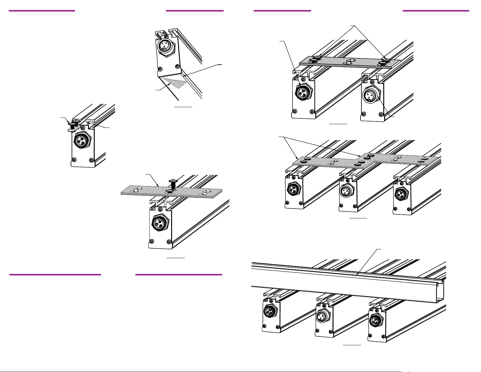
ATTACHING MULTIPLE FIXTURES (See Figure 4 and Figure 5):
1. The supplied mounting brackets can be used to attach multiple fixtures
in parallel. When attaching more than (2) fixtures, the mounting plates
can be staggered.
2. When mounting fixtures in parallel, ensure that the POWER IN
(External Threads) is mounted with the POWER OUT (Internal
Threads) next to it. An INTERCONNECT cord will be used to supply
power from one fixture to the next.
3. NO MORE THAN 16 FIXTURES CAN FED FROM ONE POWER
DROP
ATTACHING WITH UNISTRUT (See Figure 6):
1. Unistrut can also be used to mount multiple fixtures. It can be
attached with T-Slot fasteners to the fixture.
UNISTRUT
T-SLOT FASTENER
INSTALLATION INSTRUCTIONS INSTALLATION INSTRUCTIONS
FILM
FIGURE 1
FIGURA 1
T-SLOT PROFILE
ATTACH MOUNTING BRACKETS USING T-SLOT FASTENERS
(See Figure 2 & Figure 3):
1 Mounting brackets can be attached to the fixture with T-Slot
fasteners. T-Slots can be found on (3) sides of the fixture to allow an
array of mounting positions. The DOUBLE T-Slot fastener must be
loaded in the end of the T-Slot profile.
This adjustable, modular T-Slot system utilizes the modularity of
T-slot framing. T-slotted profiles are the basic building blocks of
ATTACHING MULTIPLE FIXTURES (See Figure 4 and Figure 5):
1. The supplied mounting brackets can be used to attach multiple fixtures
in parallel. When attaching more than (2) fixtures, the mounting plates
can be staggered.
2. When mounting fixtures in parallel, ensure that the POWER IN
(External Threads) is mounted with the POWER OUT (Internal
Threads) next to it. An INTERCONNECT cord will be used to supply
power from one fixture to the next.
3. NO MORE THAN 16 FIXTURES CAN FED FROM ONE POWER
MOUNTING
MOUNTING
BRACKET
IGURE 3
F
FIGURA 3
 Loading...