

Page 1

Page 1 of 5
3940 Dr. Martin Luther King Drive
St. Louis, MO 63113
P/N KIL00921449 FORM NO. K1449 ECO6-012-17 1/17
INSTALLATION, OPERATION &
MAINTENANCE DATA SHEET
LAL SERIES LED LUMINAIRE
LAL SERIES LED LUMINAIRE
CAUTION:
Before installing, make sure you are compliant with area classications, failure to do so may result in bodily injury,
death and property damage. Do not attempt installation until you are familiar with the following procedures. All
installation must comply with the applicable Electrical Code.
Make sure that the circuit is de-energized before starting installation or maintenance.
Verify that the installation is grounded. Failure to ground will create electrical shock hazards, which can cause
serious injury and or death.
IMPORTANT:
Technical information, advice and recommendations contained in these documents are based on information
that Killark believes to be reliable. All the information and advice contained in these documents is intended only
for use by persons having been trained and possessing the requisite skill and know-how and to be used by such
persons only at their own discretion and risk.
The nature of these instructions is informative only and do not cover all of the details, variations or combinations
in which this equipment may be used, its storage, delivery, installation, check out, safe operation, and
maintenance. Since conditions of use of the product are outside of the care, custody and control of Killark, the
purchaser should determine the suitability of the product for its intended use, and assumes all risk and liability
whatsoever in connection therewith.
ATTENTION:
Avant d’installer le luminaire, s’assurer que le luminaire est conforme à la classication des zones, le nonrespect de cette règle risque d’entraîner des dommages corporels et / ou matériels. Ne pas tenter d’entreprendre
l’installation avant d’être familiarisé avec les procédures suivantes. Toute installation doit être conforme au code
électrique local et / ou national et être effectuée par un électricien qualié.
Veiller à ce que le circuit soit mis hors tension avant de commencer l’installation ou la maintenance.
Vérier si le luminaire est mis à la terre. S’il n’est pas mis à la terre il pourrait causer des risques de choc
électrique susceptibles d’entraîner des blessures graves ou la mort.
Page 2

Page 2 of 5
3940 Dr. Martin Luther King Drive
St. Louis, MO 63113
P/N KIL00921449 FORM NO. K1449 ECO6-012-17 1/17
Conditions for Safe Use
The Luminaire shall only be installed where there is
a low risk of mechanical damage.
Potential electrostatic charging hazard, clean with
damp cloth.
Luminaires are designed to be installed in
Hazardous Locations: Class I, Division 2, Groups A,
B, C and D; Class II,
Division 1, Groups E, F and G; Class III; T4A, T5 or
T6 (Class I, Div. 2), T4A (Class II, Div. 1), T4A (Class
I, Div 2 / Class
II, Div. 1 Simultaneous Exposure); Type 4X; Type
6P; Marine Rated (US only);IP66; IPX7.
IEC Zone 2. IEC 60079-0:2012 IEC 60079-15:2010
and IEC 60079-31:2014 Zone 2 type of protection
Ex nA (non-sparking), Zone 21 type of protection Ex
tb (dust).
STANDARD VERSION EMERGENCY VERSION
II 3G Ex nA IIC T4/T5/T6* Gc II 3G Ex nA IIC T5/T6* Gc
II 2D Ex tb IIIC T95°C/T120°C* Db II 2D Ex tb IIIC T95°C Db
-40°C<Tamb<+65°C < 45W -20°C<Tamb<+50°C
-40°C<Tamb<+40°C/+55°C > 45W
*Depending on wattage and ambient temperature
IECEx certicate IECEx QPS 15.0010X.
ATEX certicate CML15ATEX4081X (nA)
CML15ATEX3082X (tb).
NOTE: Due to the surge protection provided in the
xture to protect the internal electronics and LEDs,
a branch circuit with the LED xture may false fail
a megohmmeter test (sometimes referred to as a
megger test). If a megohmmeter test is required,
the LED xture should be removed from the branch
circuit.
NOTE: Multiple uorescent or LED xtures
attached to a single Ground Fault Circuit Interrupter
(GFCI) may cause nuisance tripping of the GFCI.
Regulatory agencies allow a small amount of
leakage current because of the circuitry required
to mitigate possible issues with electromagnetic
compatibility (reference UL8750 and EN61347). The
summation of these leakage currents from multiple
xtures may be enough to trip a GFCI.
NOTE: For Class I, Division 2 / Class II, Division 1
/ Class I, Zone 2 Hazardous Locations, use rigid
conduit or appropriate cable connectors/ glands
rated for Class I, Division 2 Groups BCD (or IEC
Zone 2 IIC, IEC Zone 21 IIIC) hazardous areas.
NOTE: Pour les endroits dangereux Classe I,
Division 2 / Classe II, Division 1 / Classe I, Zone 2
utiliser des Conduits rigides.
LAL
LALFP
Page 3
Page 3 of 5
3940 Dr. Martin Luther King Drive
St. Louis, MO 63113
P/N KIL00921449 FORM NO. K1449 ECO6-012-17 1/17
LAL INSTALLATION NSTRUCTIONS
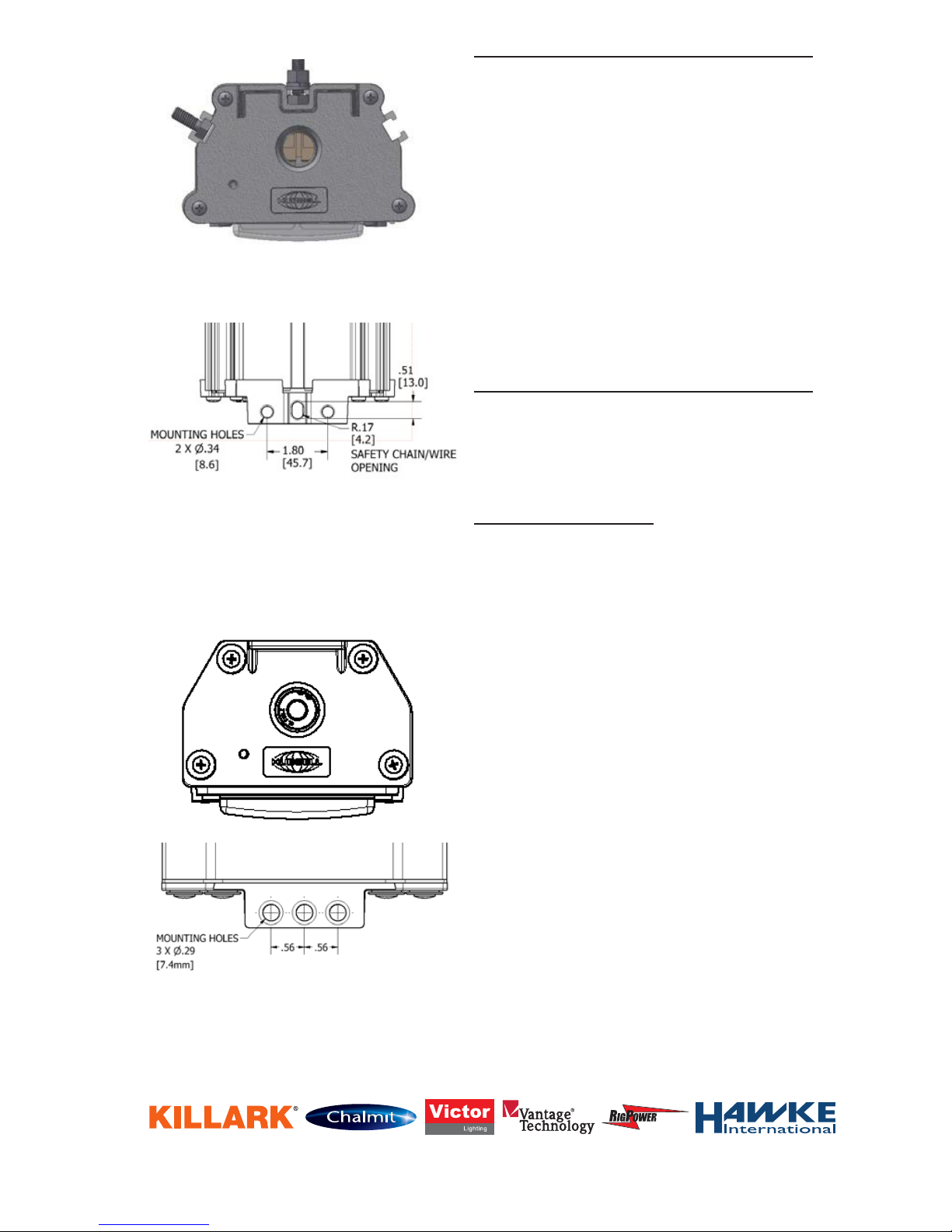
A. Channels are incorporated in the housing for
5/16” or M8 hex bolts or nuts. (See Figure 1)
1. 5/16” or M8 hex bolts can be slid into
channels for direct mounting; or used to attach
brackets which include L- brackets, Wall
Brackets, Ceiling Brackets, Beam Clamps,
and Suspension Chains etc…
2. 5/16” hex nuts or M8 hex nuts can be slid into
channels and used with eyebolts, threaded
rod etc…
B. The End Caps also have provisions for surface
or suspension mounting. (See Figure 2)
C. The “Earthquake Safety Chain Tab” is
incorporated into the endcap.
LAL INSTALLATION NSTRUCTIONS
A. The LALFP end caps have provisions for sur-
face or suspension mounting. (See Figure 3)
B. The “Earthquake Safety Chain Tab” is incorpo-
rated into the endcap.
IMPORTANT NOTE
Turn OFF electricity to circuit at main fuse or at
circuit breaker.
1. For NEC installation connection to the black
(Line), white (Neutral) and green (Ground/Earth)
can be made with appropriate wire connectors
outside of the xture, the connectors can be
placed in the xture through the hub. If the
terminal blocks are going to be used, loosen
and remove the four (4) access plate screws.
Remove access plate assembly to allow for
entry into xture.
2. If terminal blocks are used, discard the wires
on the entry side of the terminal block. Run
supply wire to xture through applicable hub.
Make watertight joint using sealing ttings at
appropriate hole. The hub in the endcap is for
¾”-14NPT (or 2 x M20 may be ordered).
3. Pull the supply wires into housing through the
conduit hub and connect the appropriate leads
using insulated wire nuts or use the terminal
blocks present. Fixtures with looping feature
may have terminal blocks at both ends of the
xture. See below for wiring battery backup
xtures.
4. Replace access plate screws if necessary.
5. Turn on electricity to verify xture is operating
properly.
Figure 1
Figure 2
(Top View)
Figure 3
Page 4
Page 4 of 5
3940 Dr. Martin Luther King Drive
St. Louis, MO 63113
P/N KIL00921449 FORM NO. K1449 ECO6-012-17 1/17
BATTERY BACKUP FIXTURES
IMPORTANT: To turn the xture completely off, an
un-switched AC power source of 120VAC to 277VAC
is required for the yellow/black and white leads.
If the yellow/black and white leads are attached
to switched power, the xture will go into battery
backup mode if the switch is turned off.
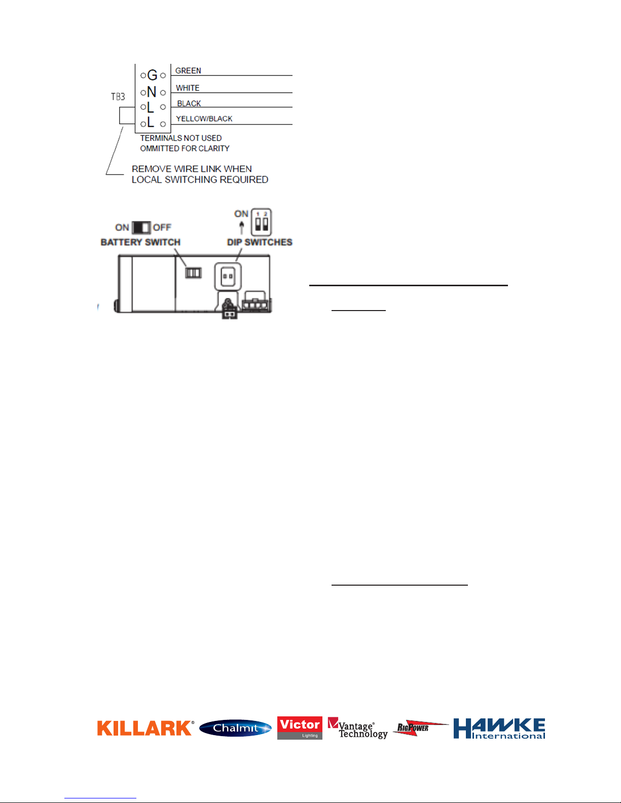
IMPORTANT: A switched or un-switched AC power
source of 120VAC to 277VAC is acceptable for the
black lead. Fixtures with terminal blocks are shipped
with a jumper between the terminals of the black
and yellow/black wire. Remove the wire link (jumper)
and attach the yellow black wire to line voltage when
local switching is required.
The battery must be charged for at least 12 hours
prior to testing.
The battery switch must be turned to the “ON”
position for the xture to operate correctly. The
xture will not light up in battery backup mode
until AC power is supplied once while the battery
switch is in the “ON” position. Thereafter, the
xture will operate in battery backup mode when
the AC power is off.
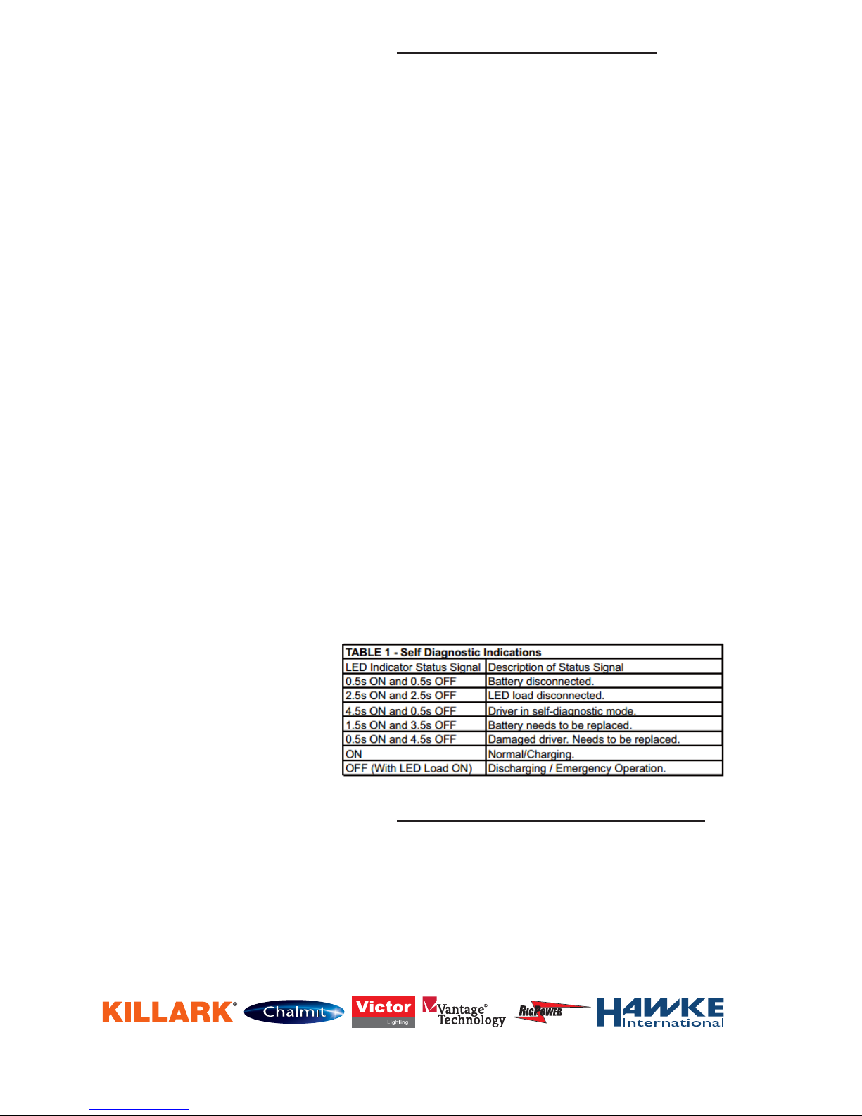
SELF DIAGNOSTIC INSTRUCTIONS/OPERATION:
The self diagnostic feature is set from the factory.
The emergency LED driver will conduct a self check
for thirty (30) minutes every thirty (30) days; and
ninety (90) minutes or one hundred eighty (180)
minutes self check every 12 months. After every self
check the LED indicator light will indicate a status
signal.
BATTERY CHANGING PROCEDURE
1. Remove one endcap from the main housing by
removing the four screws that hold the endcap
to the housing.
2. Slide the gear tray out of the housing until the
emergency driver is exposed. Remove wires
from lever nuts as necessary. To remove a wire
from a lever nut, fully push up the lever and
remove the conductor.
Page 5
Page 5 of 5
3940 Dr. Martin Luther King Drive
St. Louis, MO 63113
P/N KIL00921449 FORM NO. K1449 ECO6-012-17 1/17
REMEMBER TO SAVE ONE OF THESE SHEETS FOR MAINTENANCE PERSONNEL
3. Remove the two screws that hold the driver to
the gear tray.
4. Remove the two screws that hold the battery
compartment cover to the driver.
5. Disconnect the connector and replace the new
battery.
6. Reassemble
New xtures with batteries can be stored for 2
years in a -20°C to 30°C ambient without a need
of recharge. A fully discharged unit should not
be stored more than 6 months without being
recharged. There is low voltage disconnect of
the battery to the emergency drivers, however
as the batteries still have self-discharge they
should be recharged within 6 months to prevent
the cells from permanent capacity loss. For long
term storage, turn the battery switch to the “off”
position to prevent the cells from permanent
capacity loss.
MAINTENANCE INSTRUCTIONS
CAUTION:
Disconnect the supplying circuit before opening
xture or removing optics. To maintain maximum
light output, this xture should be cleaned
periodically. Maintenance procedures sometimes
require xtures to be hosed down for good
housekeeping. The supply circuit must be turned
OFF and the xture lens must be allowed to
cool to the ambient room temperature before
cleaning. Only mild, non-abrasive cleaning
agents should be used. The force of water
applied by a hose must not exceed 65 gallons
per minute coming from a 1” diameter hose
applied at a distance of 10 feet. Caution: Clean
polycarbonate lenses with damp cloth only to
reduce chances of static charge build up. These
periodic cleaning procedures are important to
prevent the accumulation of dust and dirt which
will impair the light output of the xture. The
polycarbonate lens should be regularly inspected
for scratches and chips and, if damaged, must
be replaced.
HIGH VIBRATION AREAS:
Periodic inspection of fastener tightness is
required; recommended every six (6) months.
Battery Back-Up Connection
with Terminal Block
 Loading...