

Page 1
Installation, Operation and
Maintenance Manual
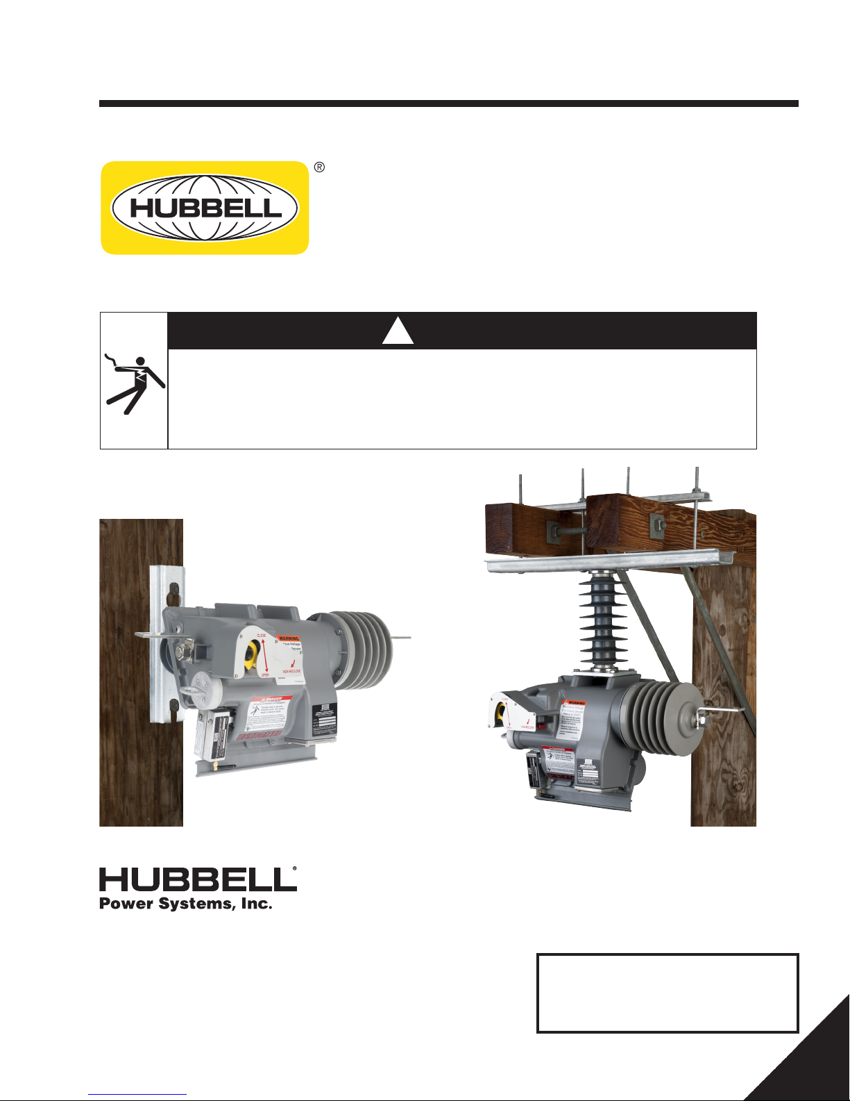
VERSA-TECH® I & VERSA-TECH® LT
Single-Phase Recloser
for Distribution Systems
!
DANGER
Electric Shock Hazard. All parts of recloser are energized.
Contact with in service recloser will cause death or severe injury.
Before contacting or servicing the equipment, or working on the electrical system, isolate and
ground the recloser from the electrical system. Verify recloser is de-energized by testing with
properly rated hot sticks and/or rubber gloves and volt meter.
8100 Churchill Avenue
Leeds, Alabama 35094
(205) 699-0840
www.hubbellpowersystems.com
NOTE: Hubbell has a policy of continuous product improvement.
We reserve the right to change design and specifications
without notice. ©Copyright 2015 Hubbell Incorporated
PSP8620311
Rev. E
IMPORTANT!
Keep this manual readily
available for future reference.
1
Page 2
Warnings
!
DANGER
Electrical equipment contains hazardous voltages. Contact with these hazards will cause death, severe personal
injury or damage equipment.
Only qualified personnel shall install, operate and maintain this equipment.
Always properly ground equipment and lock out electric power (de-energize) before maintenance. Using non-specified/unauthorized parts or
components to repair equipment, or tampering with safety devices/systems
will result in dangerous conditions which can cause death, severe personal
injury or damage to equipment. Take note of and follow all safety instructions
contained in this installation, operation and maintenance manual.
IMPORTANT
These installation, operation and maintenance instructions do not claim to cover all details or variations in
equipment. Nor do they provide for all possible conditions encountered while installing, operating or maintaining this equipment. If further information is desired or needed to address any particular installation, operation
or maintenance problem not covered in this document, contact your authorized factory representative.
The information in this document does not relieve the user from exercising good judgment in selecting equipment for suitability of application. Nor does it relieve the user from using sound practices in installation, operation and maintenance of the equipment purchased.
Note: Because Hubbell has a policy of continuous product improvement, we reserve the right to change design and specications without notice. Should a conict arise between the general information in this document and the contents of drawings or supplementary material, or both, the latter shall take precedence.
QUALIFIED PERSON
For the purpose of this manual, a qualied person is:
(a) familiar with the installation, construction or operation of the subject equipment and the hazards
involved with its installation, operation and maintenance.
(b) trained to de-energize, clear, ground, and tag circuits and equipment in accordance with established
safety practices.
(c) trained in the proper care and use of protective equipment such as rubber gloves, hard hat, safety
glasses or face shields, ash clothing, etc., in accordance with established utility safety practices.
(d) trained to render rst aid.
SUMMARY
The information in this document does not claim to cover all details or variations in equipment, nor to provide
for every possible contingency encountered with installation, operation, or maintenance. Should further information be needed or problems arise that are not covered suciently, contact your factory representative.
The contents of this document are not part of, nor do they modify, any prior or existing agreement, commit-
ment or relationship. Hubbell Power Systems, Inc. terms and conditions of sale constitute the entire obligation of Hubbell Power Systems, Inc. The warranty in the terms and conditions of sale is the sole warranty of
Hubbell Power Systems, Inc. Any statements in this document do not create new warranties or modify any
existing warranty.
2
PSP8620311
Rev. E
Page 3

Contents
Section Subject Page No.
1 — Overview
Safety Information
Ratings and Specications
Duty Cycle
Installation Alternatives
Catalog Number Matrix
Dimensions - Pole/Structure Mount
Dimensions - Crossarm Mount
2 — Installation Requirements
User Supplied Requirements
Hardware Torque Specications
3 — Receiving and Handling
Inspection
Unpacking
Components
Storage
4 — Installation
Installing NR Hookstick Adapter
Installation Options
Installation Preparation
Pole/Structure Surface Mounting
Crossarm Mounting
Connections
Place Recloser in Service
5 — Recloser Operation
Overview
Automatic Operation
Operations Counter
Non-Reclosing Lever/Hot Line Tag
Manual Operating Handle
Lockout Beacon
6 — Control Programming
Overview
Customer Supplied Requirements
Software Installation
Connecting Recloser to PC
To Establish Communications
Connecting Local Radio
Section Subject Page No.
5
Connecting to WiFi
Remote Radio Power
Radio Operation
Windows XP Local Radio Drivers Installation
Windows 7 Local Radio Drivers Installation
Windows 8 Local Radio Drivers Installation Guide
Versa-Tech Programmer Settings Tab
Connecting to a Recloser
9
Programming Settings
Minimum Trip Value
Non-Reclose /Hot Line Tag
10
Operations to Lockout
Manual Closing Delay Time
Sequence Coordination
Time-Current Curve Selection
Time-Current Curve Modiers
11
Minimum Response Time
Reclose Time
Reset Time
Cold Load Time
Cold Load Pickup
Record Manual Close
Time Stamp
Serial Number
17
Buttons Functions and General Form Controls
Real Time Monitoring
Events and Data Log
Time and Security
Scratchpad
Firmware Upgrade
7 — Testing
19
High-Potential Withstand Test
Minimum-Trip Current Test
Sequence of Operation Test
8 — Maintenance
9 — Trouble Shooting
Return Kit Packaging Instructions
42
44
46
47
PSP8620311
Rev. E
3
Page 4

Contents
Tables & Figures....................................................Page Number
Table 1-1 Duty Cycle ................................................................................. 6
Table 1-2 Recloser Catalog Number Matrix............................................... 6
Table 2-1 Hardware Torque Specifications ............................................... 9
Table 9-1 Trouble Shooting Guide............................................................ 46
Figure 1-1 Pole/Structure Face Mounting .................................................6
Figure 1-2 Crossarm Mounting .................................................................6
Figure 3-1 Components............................................................................10
Figure 4-1 Packaged NR Hookstick Adapter Kit........................................11
Figure 4-2 NR Hookstick Adapter Kit Components................................... 11
Figure 4-3 NR Hookstick Adapter Positioning for Assembling...................11
Figure 4-4 Clevis Pin Insertion for NR Hookstick Adapter......................... 11
Figure 4-5 Cotter Pin Insertion for NR Hookstick Adapter......................... 11
Figure 4-6 Pole/Structure Face Mounting .................................................12
Figure 4-7 Crossarm Mounting ................................................................ 12
Figure 4-8 Bypass Arrangement .............................................................. 12
Figure 4-9 Program/Installation Tag ........................................................ 13
Figure 4-10 Pole/Structure Mount Assembly Detail ................................... 14
Figure 4-11 Pole/Structure Mount Installation ........................................... 14
Figure 4-12 Recloser in Sling ..................................................................... 14
Figure 4-13 Crossarm Assembly Detail ...................................................... 15
Figure 4-14 Crossarm Mount Installation ................................................... 15
Figure 5-1 Feature Position .......................................................................18
Figure 6-1 Connecting Local Radio ...........................................................19
Figure 6-2 Settings Tab of Programmer Software .................................... 27
Figure 6-3 Real Time Monitoring Tab of Programmer Software .............. 36
Figure 6-4 Events and Data Log Tab of Programmer Software ................ 37
Figure 6-5 Sequence Coordination enabled on four operations
and the SC Lockout option Checked ...................................... 38
Figure 6-6 Sequence Coordination enabled on four operations
and the SC Unchecked ........................................................... 38
Figure 6-7 Time and Security Tab ............................................................ 39
Figure 6-8 Scratchpad Tab ....................................................................... 40
Figure 7-1 Recloser attached to high potential test set ........................... 42
Figure 7-2 Recloser attached to high current test set ............................. 43
Figure 8-1 Battery bayonet in the recloser .............................................. 44
Figure 8-2 Battery bayonet partially removed from recloser ................... 44
4
PSP8620311
Rev. E
Page 5
1 — Overview
Safety Information
!
DANGER
All parts of recloser are energized.
Contact with components will cause severe
personal injury, death, or property damage.
Only qualified personnel should work on or
around this equipment after becoming thoroughly familiar with this document and other
publications regarding this equipment.
!
WARNING
!
DANGER
Handle position does not indicate deenergized recloser enclosure controls
or circuit.
Contact with these components will cause severe
personal injury, death, or property damage.
Before contacting or servicing the equipment,
or working on the electrical system, isolate and
ground the recloser from the electrical system.
Verify recloser is de-energized by testing with
properly rated hot sticks and/or rubber gloves
and volt meter.
!
CAUTION
This equipment is not intended to protect human life.
Can cause death, severe personal injury, and/or equipment
damage
Follow all locally approved procedures and safety practices
when installing or operating this equipment.
Introduction
This manual is to guide you through
the programming, installation, opera-
tion and maintenance of the VERSA-
TECH® single-phase recloser. This
manual does not claim to cover
all situations that may arise during
installation. If additional information is needed, contact your factory
representative. Nor does this manual
supersede your company’s established guidelines and practices for
similar equipment. Take note of and
heed all danger, warning and cautions
contained in this document.
Qualied Person
Only qualied trained and competent
personnel that understand proper
safety procedures must select, install
and service this equipment.
Read and understand these instructions before installing, operating or
maintaining this equipment.
This guide is not a substitute for
adequate training and experience
in safety procedures for this type of
equipment.
Signal Words
The signal words “DANGER,” “WARNING”
and “CAUTION” (along with their assigned
symbol) throughout this manual indicate the
degree of hazard the user may encounter.
These symbols and words are defined as:
DANGER indicates an imminently hazardous
situation which, if not avoided, will result in
death or serious injury.
WARNING indicates a potentially hazardous
situation which, if not avoided, could result in
death or serious injury.
CAUTION indicates a potentially hazardous
situation which, if not avoided, may result in
minor or moderate injury.
Do not place the recloser in service until all
settings have been programmed and verified.
Failure to comply can result in recloser misoperation,
equipment damage, and personal injury.
Refer to sections 6 and 7 of this manual for control
programming and operation.
!
DANGER
!
WARNING
!
CAUTION
CAUTION
CAUTION used without the safety alert
symbol indicates a potentially hazardous
situation which, if not avoided, may result in
property damage.
Product
The products covered by this manual
are the VERSA-TECH® single-phase
reclosers for medium voltage electrical distribution circuits.
These products are designed for
distribution circuits only at their rated
capacities. They cannot be eld modied for capacities other than what
was shipped with the units.
Function
This product is a single-phase recloser designed to provide a means
for interrupting, sectionalizing and
isolating faults on electrical distribution systems.
PSP8620311
Rev. E
5
Page 6
1 — Overview
Ratings and Specications
VTI VTLT
Rated Maximum Voltage .....................................29.3kV
Rated Continuous Current...................................400A
Fault Make Capacity...............................................8kA
Fault Break Capacity...............................................8kA
Mechanical Operations......................................30,000
3 Second Withstand Current..................................8kA
Transformer Magnetizing Current.........................14A
Cable Charging Current.........................................25A
Line Charging Current..............................................5A
Lightning Impulse Withstand.............................125kV
60Hz, 1-Minute Withstand Voltage.....................60kV
Maximum Terminal Pad Load kg (pounds).......14 (30)
Operating Temperature.......................... -40°C to 60°C
Weight kg (pounds)...........................................21 (46)
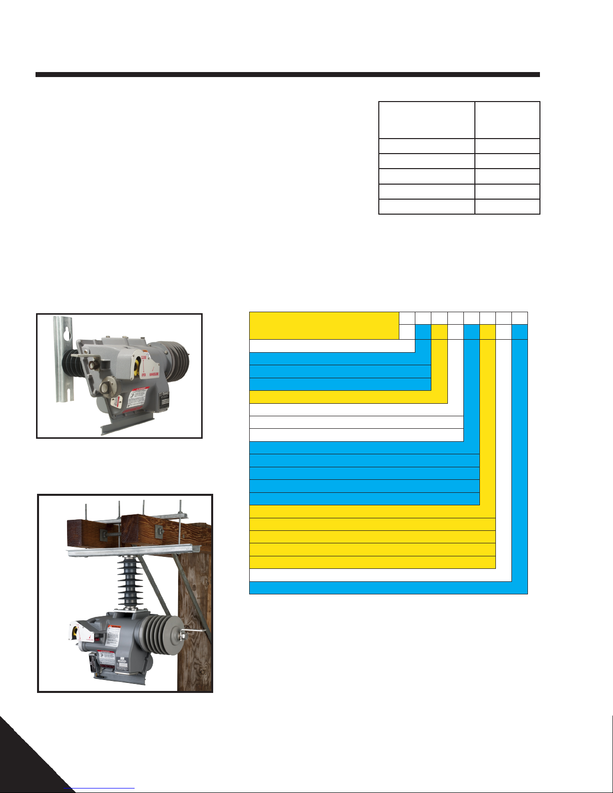
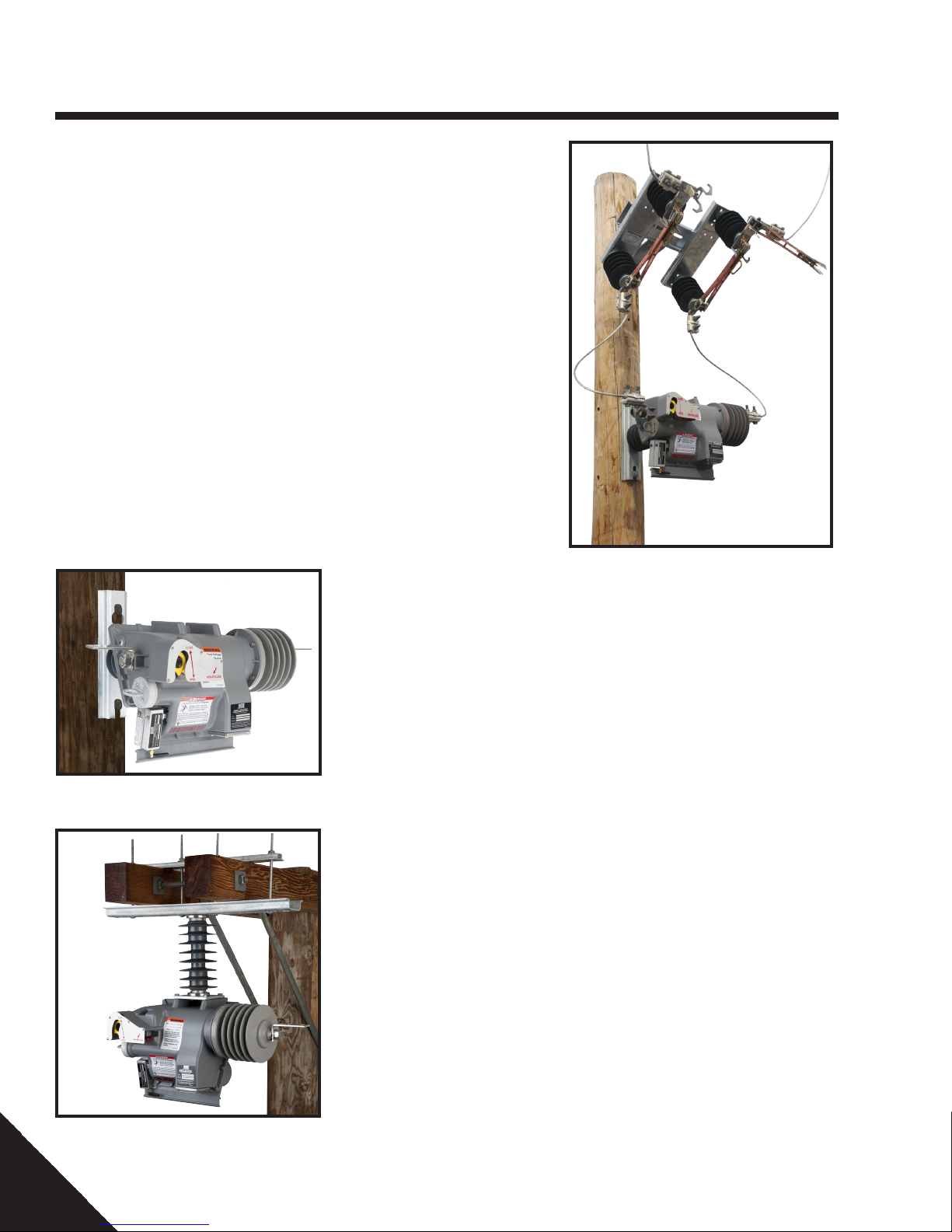
Installation Alternatives
Figure 1-1 Pole/Structure Face
Mounting
Duty Cycle
29.3kV
100A
4kA
4kA
10,000
4kA
14A
25A
5A
125kV
60kV
Percent of 8kA
Maximum Interrupting
Rating (%)
15-20 10000
25 6500
50 1800
75 700
100 400
Table 1-1 Duty Cycle
Number
of
Operations
14 (30)
-40°C to 60°C
21 (46)
Catalog Numbering System
To build your Versa-Tech Recloser, add features
from the matrix to this base number
Catalog No. PSC86
Voltage Rating 27kV 2
Versa-Tech I with FW 3.xx 1
Versa-Tech LT 4
Versa-Tech I with FW 4.xx 5
Minimum Fault Trip 30A 1
Pole/Structure Mount 1
Crossarm Mount 2
Pole with Ground Connector 3
No Connectors 1
PG (Parallel Groove) Clamps (2 total) 2
Captive Hardware 3
Single Tap Lug 4
Double Tap Lug 5
No Radio 1
Standard Performance Remote Digi Radio 2
High Performance SiFLEX Remote Radio 3
WiFi Module 4
XBee Radio 5
Pole Plaques (Additional)
Reserved 1
1 2 3 4 5 6 7 8
2 X 1 X X X X 1
Position
Figure 1-2 Crossarm Mounting
6
The number in Position 7 is the number of pole plaques in addition to the one
included with each recloser (Ex: 3 is 3 more for a total of 4)
NOTE: For more information on the Versa-Tech II Single-Phase Recloser,
please refer to Catalog 10EE on the Hubbell Power Systems website.
PSP8620311
Rev. E
Page 7
1 — Overview
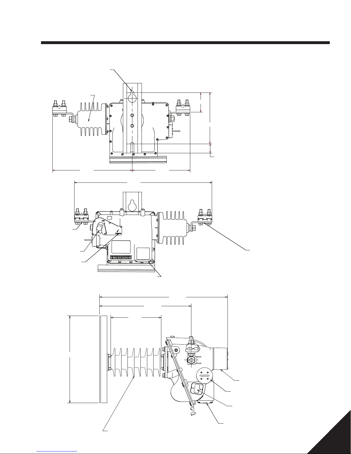
Dimensions - Pole/Structure mounting
MOUNTING HOLES FOR
5/8" (15mm) BOLTS
11" (27.9cm) CENTER
TO CENTER NOMINAL.
VACUUM INTERRUPTER
17.1 12.4
29.5
4.2
Back View
11.0
2.0
2-HOLE NEMA
PAD (STANDARD)
TYPICAL
OPERATING LEVER
NON-RECLOSE
LEVER
15.0
LOCKOUT INDICATOR
BEACON AND COUNTER
8.7
15.8
22.0
Front View
2-HOLE NEMA
PAD (STANDARD)
TYPICAL
Side View
OPERATING LEVER
LEAKAGE DISTANCE - 39.4"
PSP8620311
Rev. E
BATTERY PACK
(HOT STICK REPLACEABLE)
SERIAL PROGRAMMING PORT
LOCKOUT INDICATOR BEACON
AND COUNTER
7
Page 8
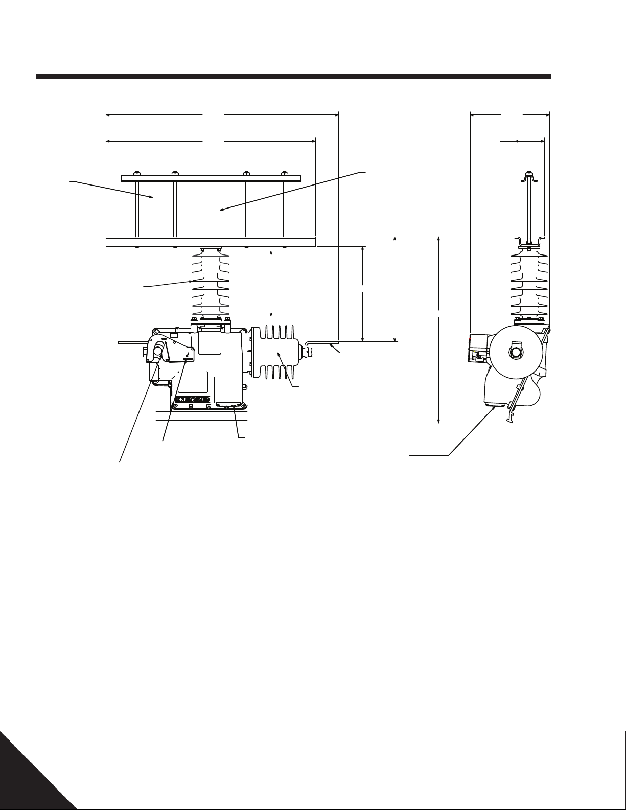
1 — Overview
31.1
10.6
Dimensions - Crossarm mounting
ADJUSTABLE
3" - 9-1/2"
LEAKAGE DISTANCE - 39.4"
OPERATING LEVER
28.0
NON-RECLOSE LEVER
8.7
VACUUM INTERRUPTER
LOCKOUT INDICATOR BEACON
AND COUNTER
ADJUSTABLE
5-1/8" - 10-1/4"
TYPICAL
12.7
2-HOLE NEMA
PAD (STANDARD)
TYPICAL
14.0
LOCKOUT INDICATOR BEACON
AND COUNTER
4.0
24.9
Side ViewFront View
8
PSP8620311
Rev. E
Page 9

2 — Installation Requirements
User Supplied Requirements
The following is required for installation.
Be sure to have these items on hand
before beginning installation.
Safety Equipment (PPE)
• Hard hat
• Steel-toe work boots
• Appropriate eye protection per your
company’s policy
• Other safety equipment as required by
your company’s policies
Hardware
• 5⁄8 inch (16 mm) galvanized thru-bolts
(or equivalent) long enough to pass
through the center of the utility pole,
plus 3 inches (75 mm)
• Curved galvanized washers for the 5⁄8
inch (16 mm) thru-bolts
• Galvanized nuts for 5⁄8 inch (16 mm)
thru-bolts
• Flat galvanized washers for 1⁄2 inch
(12 mm) and 5⁄8 inch (16 mm)) lag
screws
Electrical
• Terminal pad connectors (if not ordered with switch)
• Connector sealing paste (CHANCE ZLN
or equivalent)
• Surge arresters and wire (if needed)
Options
• BP3 By-Pass Switch (for appropriate
Cat. No., see Catalog Section 14B)
• Jumper Wire, 100/400 Amp minimum
capacity (VTLT/VTI)
• M3 Disconnect Switch (for appropriate
Cat. No., see Catalog Section 14B)
Hardware Torque
Specications
It is the installing personnel’s responsibility to be sure all threaded fasteners
are installed with the correct torque. All
user supplied hardware is to be torqued
according to company standards.
Recloser and connector hardware torque
specifications are listed in Table 2-1.
User Supplied Hardware
Item ft-lb N•m Notes
5⁄8 inch (16 mm) thru-bolts N/A N/A Company standards apply
5⁄8 inch (16 mm) lag screws N/A N/A Company standards apply
Terminal connectors N/A N/A Company standards apply
Hubbell Supplied Hardware
Item ft-lb N•m Notes
3/8 inch Crossarm Mount bolts N/A N/A Company standards apply
3/8 inch Insulator Mount bolts 15 20
1/2 inch Terminal bolts 60 81
Table 2-1 Hardware Torque Specications
Hubbell Power Systems, Inc.
Supplied Requirements
All necessary components and hardware
specific to the installation of the VERSATECH® recloser ordered are included.
Carefully check the components and
hardware items against those listed in
Section 3.
Contact your factory representative if any
parts are missing.
PSP8620311
Rev. E
9
Page 10
3 — Receiving & Handling
Inspection
1. Inspect the packaging for obvious
shipping damage.
2. Open and thoroughly inspect the product
for hidden damage.
3. Note any damage on the “Bill of Lading”
prior to accepting the delivery.
4. Check the material nameplate against the
shipping list to ensure the correct material
has been received. In case of shortage
or incorrect material, immediately notify
your factory representative or customer
service.
NOTE: Documentation of visible
shipping damage can determine the
outcome of any damage claim. Notifying
the carrier of concealed damage within
15 days is essential to resolving or
minimizing unsettled claims. Immediately
file your claim and notify your factory
representative.
Unpacking
1. Locate the Hubbell USB Drive that is
enclosed with this manual. The USB
drive should be in the custody of the
personnel who will be responsible for the
programming of the recloser.
1. Carefully remove all items from the
packaging. Exercise caution and do not
drop the unit or strike the skirted end on
anything as this may damage the vacuum
interrupter or mechanism.
1. Refer to Figure 3-1 to familiarize yourself
with all components.
NOTE: When batteries are removed for
more than seven days, the time stamp
chip will stop keeping time. If time stamp
feature is required, the time stamp can
be reset before placing the recloser in
service. (See Section 7.)
Storage
If the recloser is not going to be put into service
immediately, re-pack all components in the
factory package to minimize storage damage
and to ensure good operating conditions in the
future. Hubbell Power Systems recommends
that the recloser be stored indoors or under
cover, off the ground, not subject to direct sun,
rain or snow.
If the storage area temperature exceeds
100°F, remove the batteries and store in a
cool, dry area.
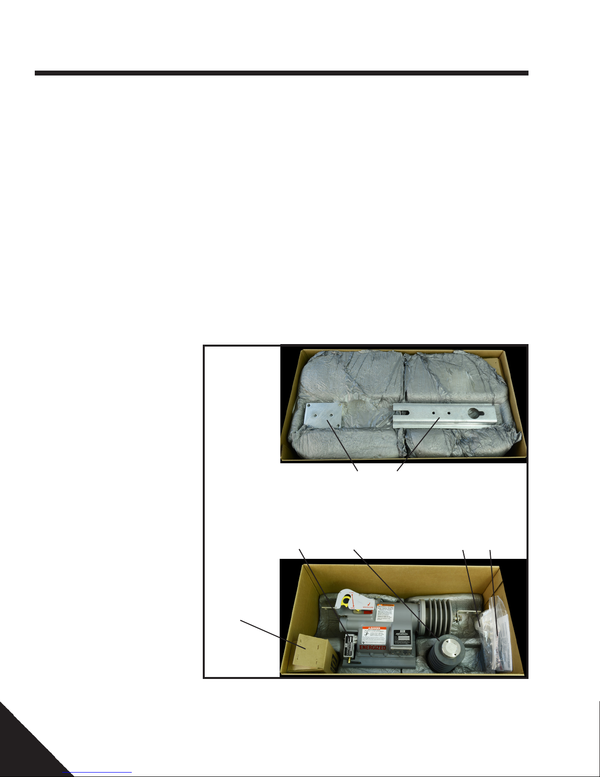
10
Radio
(optional)
Battery Bayonet
Figure 3-1 Components
Mounting
Brackets
Insulator
Mounting
Fasteners
and
PG Clamps
Instructions,
Flash Drive
and NR
Handle
Adapter Kit.
PSP8620311
Rev. E
Page 11
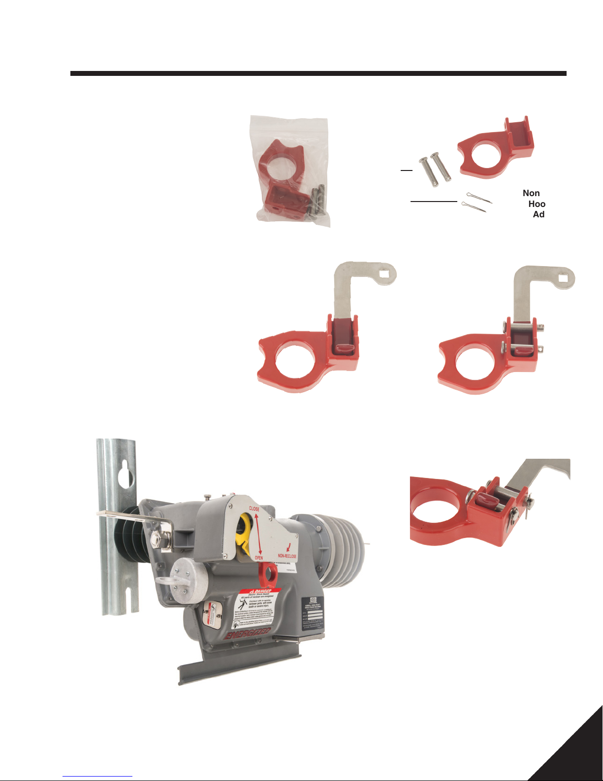
4 — Installation
Installing the Optional NonReclose Hookstick Adapter
The Non-Reclose (NR) Hookstick
Adapter Kit is an adapter that can
be attached to the NR handle on the
Versa-Tech Recloser to allow for easier
operation with a hookstick. The addition
of the adapter is not mandatory. The
same gentle pull action, as used with
the NR handle, is utilized for operation.
Figure 4-1 shows the NR Hookstick
Adapter Kit as packaged. Figure 4-2
shows the components.
Step 1: Pull the Non Reclose (NR)
handle to the down position.
Step 2: Take the NR Hookstick Adapter
and place it so that the NR handle is
positioned as shown in Figure 4-3.
Figure 4-1
Clevis Pins
Cotter Pins
Non Reclose
Hookstick
Adapter
Figure 4-2
Step 3: Insert the clevis pins through
the holes of the NR Hookstick Adapter as
shown in Figure 4-4.
Figure 4-3 Figure 4-4
Figure 4-5
Step 4: Place the cotter pins though the
holes on the clevis pins. Fold the legs of
each cotter pin as shown in Figure 4-5.
NOTE: The Non Reclose Hookstick
Adapter operation has not been tested
under icing conditions.
PSP8620311
Rev. E
11
Page 12
4 — Installation
Installation Options
VERSA-TECH® single-phase reclosers are designed for outdoor pole or
structure mounting and application on
overhead electrical distribution systems.
The energized recloser is insulated from
the pole/structure by a polymer insulator.
The VERSA-TECH® Single Phase Electronic Recloser is available in two basic
mounting configurations:
1. Pole/Structure mounting (see Fig. 4-1)
2. Crossarm mounting (see Fig. 4-2).
Refer to the catalog number of the unit. The
fourth (4th) character position indicates
the mounting arrangement, e.g., the "1" in
the seventh position of (PSC86)2X11XXX
indicates a Pole/ Structure mounting. A “2” in
this position indicates Crossarm mounting,
e.g., (PSC86)2X12XXX.
Figure 4-8 Bypass Arrangement
Figure 4-6 Pole/Structure Mounting
Hubbell Power Systems recommends the
use of a by-pass switch in parallel with the
recloser. This arrangement allows the unit to
be easily taken out of the circuit for service,
should the need arise. It also allows all
connections to be made without picking up
load current with the jumper connections
(see Fig. 4-3).
LIGHTNING ARRESTERS NOTE:
Hubbell Power Systems recommends
placing appropriately rated lightning
arresters as close as possible on both
the source and load sides of the recloser.
(Refer to Ohio Brass catalog.)
Figure 4-7 Crossarm Mounting
12
PSP8620311
Rev. E
Page 13

4 — Installation
!
WARNING
Follow all appropriate OSHA and company
work rules in the installation of this equipment.
All clearances, cover-up and personal protective equipment must be used. Failure to follow
these instructions may result in damage to
equipment, personal injury or death.
!
CAUTION
The unit must be mounted horizontally as illustrated in this manual. Failure to mount in
this attitude may result in improper operation
of the interrupter.
!
WARNING
Do not store or lay the recloser in mud, snow or
water.
This could contaminate the insulation over the
interrupter leading to electrical flashover at the
system voltage.
A clean, dry storage environment is recommended.
!
CAUTION
Do not place the recloser in service until all settings have been programmed and verified.
Failure to comply can result in recloser
misoperation, equipment damage, and personal
injury.
Refer to sections 6 and 7 of this manual for control
programming and operation.
Installation Preparation
1. Program the unit with the desired
parameters as outlined in Section 6 of
this manual. Record the settings on the
supplied tag and attach the tag to the
operating handle for reference during
installation (Fig. 4-4).
2. Prior to installation, verify vacuum
interrupter integrity by applying 50/60 Hz
40kV AC across the open contacts for 60
seconds. (See Section 7.)
Complete this tag when unit is programmed and tie to the operating handle of the unit.
Hubbell Versa-Tech® Single Phase Recloser
This unit has been programmed to the following settings by: _______________ Date: _____________
Operations to Lockout: 1 2 3 4
Minimum Trip (Amps): ___________ Reset Time (sec): ____________
Min. Response Time (mSec): __________ Cold Load Time: ____________
Sequence Coordination Enabled ❑ Min. Response Enabled for Operation 1 2 3 4
Operation #1: TCC1 TCC2 TCC1 Curve: _____________
Modier: _____________
Operation #2: Reclose Time 1 (sec): ____ Curve: TCC1 TCC2
TCC2 Curve: _____________
Modier: _____________
Operation #3: Reclose Time 2 (sec): ____ Curve: TCC1 TCC2
Operation #4: Reclose Time 3 (sec): ____ Curve: TCC1 TCC2
Location for Installation: _______________________________________________________________
Installed by: ______________________________________________ Date: _____________________
Figure 4-9 – Program/Installation Tag
PSP8620311
Rev. E
13
Page 14
4 — Installation
Pole/Structure Surface
Mounting
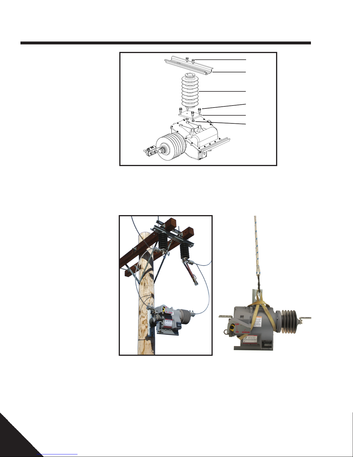
1. Refer to Figure 4-5 for assembly detail
and Table 2-1 for torque specifications.
• Assemble the insulator (1) to the
rectangular steel adapter plate (2)
using two 3/8" X 1" bolts and split lock
washers (3) as shown.
• Assemble the mounting bracket (4) to
the opposite end of the insulator (1)
using two 3/8" X 1" bolts, flat washers
and split lock washers (5) as shown.
• Attach the insulator/bracket/adapter
plate to the four threaded bosses on
the flat side of the body of the recloser
as shown. Use four ss 3/8" X 1-1/4"
bolts, flat washers and split lock
washers (6).
NOTE: Do not attach to the 4 threaded
holes on the top of the body. These
attachment holes are used only on the
crossarm mounting arrangement.
2. Determine the mounting location on the
pole. The pole mount uses 2 bolts, 5/8"
diameter on 12" centers.
3. Drill the appropriate holes through the
pole.
5
4
1
6
2
3
Figure 4-10 Pole/Structure Mount Assembly Detail
4. Install the bolt in the top hole.
NOTE: The head of the bolt must be on
the side of the pole where the recloser
will be mounted. Install the nut and
washers on the back side. Leave
approximately 2" of bolt exposed under
the head for the keyhole slot in the
mounting bracket.
5. Using a nylon sling, sling the unit as
shown in Figure 4-7.
CAUTION: Do not use a metal sling or
chain as this may damage the unit.
6. Using suitable means, lift the unit into
position.
CAUTION: Do not allow recloser to
impact or collide with pole or other
objects as it is lifted and installed.
7. Ensure the top bolt engages the small
portion of the “keyhole” slot.
Figure 4-11 Pole/Structure
Mount Installation
Figure 4-12 Recloser in Sling
8. Install the bottom bolt/washers and nut.
9. Tighten the hardware per Table 2-1.
14
PSP8620311
Rev. E
Page 15
4 — Installation
Crossarm Mounting
This configuration is intended for application
to a double crossarm structure.
This is the preferred arrangement if three
units are to be mounted.
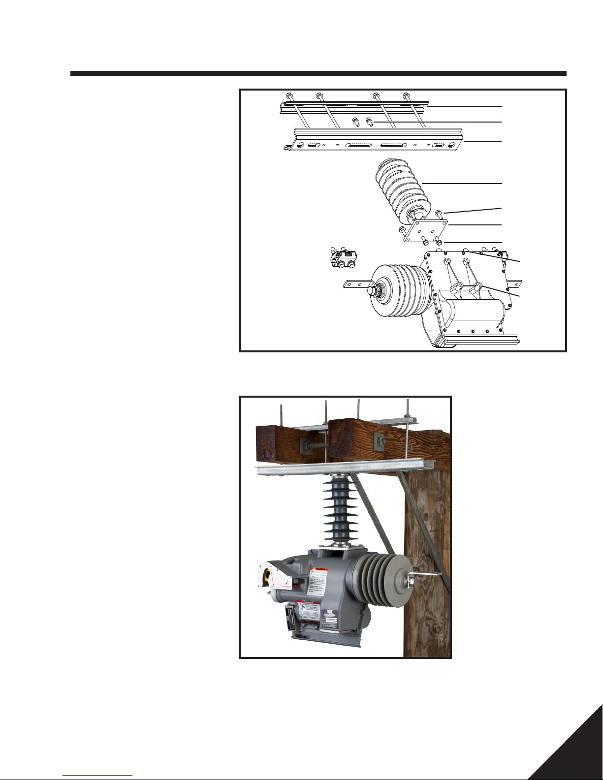
1. Remove the four 3/8" X 5/8" bolts from top
mounting flange (8) and use to fill the four
holes on the cover (9).
2. Refer to Figure 4-8 for assembly detail
and Table 2-1 for torque specifications.
• Orient the insulator (1) so the skirts
will shed water towards the rectangular
steel adapter plate (2) and assemble
using two 3/8" X 1" bolts and split lock
washers (3) as shown.
• Assemble the mounting bracket (4)
to the opposite end of the insulator
(1) using two 3/8" X 1" bolts, split lock
washers and flat washers (5) as shown.
• Attach the insulator/bracket/adapter
plate to the four threaded bosses on
the top of the body of the recloser as
shown. Use four ss 3/8" X 1-1/4" bolts,
flat washers and lock washers (6).
3. Using a nylon sling, sling the unit as
shown in Figure 4-7.
7
5
4
1
6
2
3
8
9
Figure 4-13 Crossarm Assembly Detail
CAUTION: Do not use a metal sling or
chain as this may damage the unit.
4. Using suitable means, lift the unit into
position.
5. Install the back plate (7), and four 3/8"
X 7-1/2" carriage bolts/lock washers/
and square nuts. Adjust the bolt
spacing as necessary to fit the crossarm
arrangement.
6. Tighten the hardware per Table 2-1.
NOTE: Make sure the terminal L brackets
(2-hole NEMA pads) are not bent in any
angle. Terminal L bracket nuts, sixteen
screws around the recloser and six screws
around the vacuum interrupter are not to be
removed or re torqued by any means. The
integrity of the contacts is compromised if the
above factory standard torqued hardware is
tampered.
Figure 4-14 Crossarm Mount Installation
PSP8620311
Rev. E
15
Page 16

4 — Installation
Connections
1. Wire brush the jumper conductors and
terminal pads.
2. Apply contact aid, such as CHANCE ZLN
to the contact surfaces. Install the recloser
end of the jumpers. Tighten the terminal
bolts per Table 2-1. if used.
3. Make sure the recloser handle is in the
open position and the contacts are open.
4. Connect the jumpers to the power source.
Tighten the terminal bolts per Table 2-1.
5. The recloser is a bidirectional current
sense device and can be connected
either way to the source or the load side
of the feeder.
NOTE: The unit will not close with the
Non-Reclose handle down if in HLT only
mode.
CAUTION: Avoid applying side loads to
vacuum interrupter end of recloser when
making connections to terminal pads.
Place recloser into service
1. Using appropriately rated hot stick, pull
the red non-reclosing lever to the down
position.
2. Using appropriately rated hot stick, install
the battery pack by inserting; align the
pins in the slots, push and turn clockwise
to lock in place.
3. Ensure all connections are tight and
properly connected.
4. Using an appropriately rated hot stick,
close the unit by pushing the yellow lever
to the extreme up position and release.
You should hear the unit close.
5. Using an appropriately rated hot stick,
open the by-pass switch
6. Push the red non-reclosing lever to the
up position. The unit is now in normal
operating mode.
!
DANGER
Electric Shock Hazard. All parts of recloser are energized.
Contact with in service recloser will cause death or severe injury.
Before contacting or servicing the equipment, or working on the
electrical system, isolate and ground the recloser from the electrical system. Verify recloser is de-energized by testing with properly
rated hot sticks and/or rubber gloves and volt meter.
!
WARNING
Do not ground the recloser.
Grounding the recloser can result in recloser misoperation,
equipment damage and personal injury.
!
WARNING
Open the recloser before making final connections.
Failure to comply can result in an electrical arc which can cause
death, personal injury or equipment damage.
Before making any connections to the power line, pull the red non-reclosing lever down and open the recloser by pulling the yellow handle
to the down position.
!
WARNING
Do not open the by-pass switch while the recloser is open.
Failure to comply can result in an electrical arc which can cause
death, personal injury or equipment damage.
16
PSP8620311
Rev. E
Page 17

5 — Recloser Operation
Overview
The VERSA-TECH® Recloser is a unique
and patented approach to recloser design.
The interrupter, drive mechanism, control,
and housing are raised to the system
potential. The entire assembly is then
insulated from ground using a standard
polymer post insulator. This approach
allows a compact simplified design and also
eliminates the potential for an insulation
breakdown failure.
The fault interruption occurs in the recloser’s
vacuum interrupter. This vacuum interrupter
has state of the art contacts utilizing axial
magnetic fields to interrupt in diffuse mode
for maximum interrupter life. The vacuum
interrupter is supported by an insulating
support housing with bonded epoxy
composite formulation over-molding for
maximum weather resistance.
The drive for the vacuum interrupter is
provided by a mechanism with a magnetic
actuator. The actuator has a rare-earth
neodymium magnet, which provides the
latching and holding force for the vacuum
interrupter in the closed position. A spring
provides the pressure to hold the vacuum
interrupter in the open position. Together
the rare-earth magnet and the spring
arrangement allow the mechanism to be
stable in the open or closed position without
the need for external power. To open the
vacuum interrupter a coil on the magnetic
actuator is pulsed in one direction. To close
the same coil is pulsed in the other direction.
Energy to open and close the recloser is
provided by a set of capacitors.
The control for the recloser is provided by
a microprocessor based electronic circuit.
The control is designed to allow complete
flexibility and user choice of minimum
trip, time-current curves and sequencing
parameters. User access to all parameters
is provided through an RS-232 serial
connection. Current sensing for the control
occurs through a 1000:1 current transformer.
No external transformer power for the
recloser is required. Power for the control
and the mechanism is converted from fault
or load current using two power current
transformers. The open and close capacitors
needed to drive the recloser are charged by
the load or fault current through the power
current transformers. Using this approach
the recloser will continue to open and close
as necessary without the need for external
power or even the hot-stick replaceable
lithium battery pack. The lithium battery
pack provides power to the real time clock,
beacon, the remote radio when current
is less than 10A when the Non-Reclose
handle is engaged (See Recloser Operation
Section) and after lockout or manual open.
Automatic Operation
The VERSA-TECH® Recloser, when in the
closed position, operates automatically per
the programmed user settings.
Operations Counter*
Refer to Figure 5-1 for Counter location.
Operations counter is an electromechanical
counter, which counts open operations
both manual and automatic initiated by the
control.
*Applicable to VTI only. External operations
counter is not present on the VTLT.
Non-Reclosing Lever/Hot
Line Tag
Refer to Figure 5-1 for the location of
the Non-Reclosing Lever (red lever). The
handle is shown in the normal or UP
position. In this position, the recloser will
follow the automatic sequence it has been
programmed for.
Legacy Versa-Tech I Reclosers
(manufactured July 2011 and
earlier):
The Versa-Tech Programmer User Interface
(UI) allows the programming of the NonReclosing (NR) lever to a single
functionality mode only (Non-Reclose
Mode OR Hot Line Tag mode). If the NR
Mode Only is selected when the red lever is
rotated 90 degrees clockwise to the down
position, the recloser will trip using TCC1
and lockout on any current above minimum
trip. If the Hot Line Tag (HLT) Mode Only is
selected when the red lever is rotated 90
degrees clockwise to the down position, the
recloser will trip instantaneously and lockout
on any current above minimum trip.
Versa-Tech Reclosers manufactured
after July 2011 (Versa-Tech I and
Versa-Tech LT):
The Versa-Tech Programmer User Interface
(UI) allows the programming of the NonReclosing (NR) lever to a dual
functionality mode (Non-Reclose/Hot Line
Tag) or a single functionality mode (Hot Line
Tag Only). When the "NonReclose/Hot Line Tag" option is selected,
the recloser will be in a Non-Reclose mode
when the red lever is rotated to the down
position one time. In the NR mode, the
recloser will trip using TCC1 and lockout
on any current above minimum trip. If the
red lever is rotated to the down position
twice within 30 seconds, the recloser will be
placed in Hot Line Tag mode. The Hot Line
Tag Mode is an instantaneous trip mode.
When the "Hot Line Tag Only" option is
selected, the recloser will always be in Hot
Line Tag mode when the red lever is placed
in the down position.
Note for Versa-Tech I Reclosers with
Firmware 4.xx: For Versa-Tech I Reclosers
with firmware version 4.xx, whenthe recloser
locks out on Hot Line Tag, the solenoid can
be closed only after the Hot Line Tag mode
is disabled. This is accomplished by first
rotating the red lever back to its original
position (UP) and then by pushing the
Manual Handle (yellow handle) back to its
UP position. If the Manual Handle is UP prior
to putting the red lever to the UP position,
the Manual Handle must be pulled DOWN
and then pushed to the UP position in order
for the solenoid to close.
All Versa-Tech I and Versa-Tech LT
Reclosers: Hot Line Tag is an instantaneous
trip mode. As long as the capacitors are
fully charged, the Versa-Tech will trip in
1/2 cycle or 8ms while in HLT. Hot Line Tag
takes precedence over Cold Load Time and
Non-Reclose mode. Cold Load Time takes
precedence over Non-Reclose Mode. The
red lever is also used to turn on the remote
radio (Digi/XBee, SiFLEX, or WiFi) when
line current goes below 10A. To turn on
the remote radio, pull the red lever DOWN
and then push it UP within 30 seconds. the
radio will then automatically shut OFF after
10 minutes of communications inactivity to
minimize battery drain. If the red lever is
left in the DOWN position, the radio will be
powered for 60 minutes before automatically
shutting OFF.
PSP8620311
Rev. E
17
Page 18

5 — Recloser Operation
Manual Operating Handle
Refer to Figure 5-1 for Manual Operating Handle location. The manual operating handle is designed to allow manual operation of the
recloser with a hotstick. If the manual handle operating handle is rotated 90 degrees counter-clockwise to the down (open) position the
recloser will open and interrupt the distribution circuit. Pulling the manual handle down anytime will manually pull open the mechanism and
the vacuum interrupter opening the recloser.
Closing the recloser after a manual open or automatic lockout can be done by moving the manual operating handle clockwise 90 degrees
to the up (closed) position. This will activate the electronic control, which will initiate the close sequence. Before the recloser is closed
the close capacitor is charged to the required level from the lithium batteries. When it reaches the necessary charge level, the magnetic
actuator closes the recloser. This process from movement of the handle until the recloser closes may take a few seconds.
Lockout Beacon
Refer to Figure 5-1 for Beacon location. The Lockout Beacon is a unique feature which is designed to aid the utility lineman in identifying
a locked out recloser. This high intensity sunlight visible amber LED will flash once every 3 seconds when the recloser has sequenced to
lockout. The lithium batteries provide the power for the flashing beacon.
Versa-Tech I Reclosers with FW 3.xx and Versa-Tech LT Reclosers:
The beacon will continue to flash every 3 seconds until the lineman closes the recloser or 1 hour has passed. After 1 hour, the flashing
beacon will automatically shut OFF. The beacon is also utilized when the recloser is manually opened. When manually opened, the beacon
will continue to flash until the recloser is closed or 60 seconds has passed.
Versa-Tech I Reclosers with FW 4.xx:
The beacon will continue to flash every 3 seconds until the lineman closes the recloser or 4 hours have passed. After 4 hours, the flashing
beacon will automatically shut OFF. The beacon is also utilized when the recloser is manually opened. When manually opened, the beacon
will continue to flash until the recloser is closed or 4 hours have passed.
Manual Operating Handle
Non-Reclosing
Lever
Lockout Beacon
18
Operations Counter*
Figure 5-1 Feature position
*Applicable to VTI only. External
Operations Counter is not present
on the VTLT.
PSP8620311
Rev. E
Page 19

6 — Control Programming
Overview
The VERSA-TECH® Recloser can be fitted with an
optional radio which will allow settings, diagnostics and
scratchpad to be viewed remotely while the unit is in
service. The radio will also allow settings, timestamp and
scratchpad to be changed while the recloser remains in
service. The remote radio options are Digi/XBee 900MHz,
SiFLEX 900MHz, or Wireless (WiFi) 2.4GHz. The remote
radio is adapted to the serial port on the recloser. In
order to accomplish communication with the Digi/XBee or
SiFLEX remote radios, a separate Digi/XBee or SiFLEX
local radio is needed. The local radio is a USB powered
radio that is attached to the laptop or other personal
computer running the Versa-Tech Programmer User
Interface. Communication with the WiFi remote radio is
accomplished through the Wireless Network on the laptop
or personal computer.
Customer Supplied Requirements
Personal computer with Microsoft® Windows® XP,
Windows® 7 32/64 bit or Windows® 8 operating system,
a USB to RS-232 serial cable if a direct connection is
desired, PC wireless card for connection through the WiFi
remote radio, local Digi/XBee radio with USB Type B serial
cable for connection through the Digi/XBee remote radio,
or local SiFLEX radio with USB Type B serial cable for
connection through the SiFLEX remote radio.
Software Installation
To Establish Communications
If external local radios are required, they must be connected before
launching the programming software. If a WiFi remote radio is
utilized, connection to the wireless network card on the PC must
be established prior to launching the programming software. Once
the programming software is launched, click "Refresh List" on the
User Interface to scan for the reclosers within the range and "Auto
Connect" to connect to the selected detected devices. See Control,
Programming > Connection Section 6 of this manual.
Connecting Local Radio
The local radio is controlled and powered by connecting a USB cable
between the module and a personal computer as shown in Figure
6-1. Communication with the local radio is accomplished through
the recloser programmer software (see section 6) provided with the
recloser.
Connecting WiFi
The Versa-Tech Recloser uses a 2.4GHz RN171 remote radio to
communicate over WiFi (without the need for a local radio). Wireless
communication is established to the Versa-Tech I (FW 3.xx or 4.xx)
and Versa-Tech LT through the internal wireless card on a PC and
the Versa-Tech Programmer software (UI version 4.50.15 or higher).
Wireless communication with a Versa-Tech I with firmware version
4.xx and Versa-Tech LT can be also be established using the VersaTech Recloser Programmer Version 3.1 iPad app. The WiFi radio has
the capability to communicate up to 100 feet from the recloser.
Recloser programming software must be installed on the
computer proir to use. Installation software is provided
with each recloser on a Hubbell USB drive or is available
on the Hubbell Power Systems website.
Connecting Recloser to PC
The customer supplied DB9 Male/Female serial cable is
used to directly connect the recloser to a PC (hardwired).
Wireless communications can be established utilizing the
appropriate 900MHz remote/local radio combination or
the PC wireless networks/WiFi remote radio combination.
Figure 6-1 Connecting Local Radio
PSP8620311
Rev. E
19
Page 20

6 — Control Programming
Remote Radio Power
When the VERSA-TECH® Recloser is in service with a load current of 10 Amps or more, the attached remote radio is on and powered from
the recloser's internal current transformers. If the recloser is not in service or the load current is less than 10 Amps, the radio is ON only for
10 minutes and must be powered from the recloser internal batteries. To turn on the radio, pull down the Non-Reclosing handle (red lever)
and then push it up. The radio then will automatically shut off after 10 minutes of communications inactivity to minimize battery drain. If the
Non-Reclosing Lever is left in the down position without the ample 10 Amps of load current, wireless communications will time out in 60
minutes.
NOTE: Whenever the remote radio on the recloser is changed or swapped with another remote radio, make sure that the battery is pulled
out of the recloser for at least 60s for the control to completely reset. After the reset, plug in the new remote radio to the DB 9 port of the
recloser followed by the battery pack insertion. This process lets the remote radio get correctly identified by the Versa-Tech Programmer.
Radio Operation
The Digi/XBee and SiFLEX radios communicate with each other on a 900MHz channel which utilizes frequency hopping to minimize
interference from other radio frequency sources. The RF modules are FCC compliant. The communication range is up to 500 feet open air.
The radios use a two-part addressing scheme to help ensure that messages from only authorized sources are passed to a recloser.
First, all VERSA-TECH® Recloser local and remote radios have a unique user transparent address which is transmitted during
communications. The recloser local radio will accept messages only from a remote radio with the same address. This helps prevent other
900MHz radios from making unauthorized communications with VERSA-TECH® Reclosers.
Second, each remote radio is programmed with a unique fixed radio communications address. This address allows users to differentiate
between multiple reclosers all within a 500-foot transmit/receive range. The remote radio will discard any message that does not include
its unique radio communications address. The local radio has provisions through the recloser programmer software (see Section 6) which
permits selecting any recloser's remote radio communications address.
20
PSP8620311
Rev. E
Page 21

6 — Control Programming
Windows XP Local Radio Drivers Installation Guide
Before using the Local Radio for the first
time, the Windows® device drivers will
have to be installed. The following steps
illustrate the process.
1. Download the radio drivers from the
Hubbell Power Systems website. Be sure to
extract the files.
2. Connect the USB plug to USB port on
the radio.
3. Connect the other end of the USB cord
to USB port on the PC/laptop.
4. “Found New Hardware” Wizardshould
start.
5. At the “Can Windows connect to
Windows Update to search for
software?” window, select “No, not at
this time” and click <NEXT>
6. Insert the provided Hubbell USB drive.
Found New Hardware wizard should
automatically continue, if not, click
<NEXT>.
7. Click Finish.
8. “Found New Hardware” Wizard should
start again. This time it is adding the
USB port.
9. Repeat Steps 5 to 7 above.
NOTE: Because Hubbell has a policy of continuous product improvement, we reserve the right to change
design and specications without notice.
PSP8620311
Rev. E
21
Page 22

6 — Control Programming
10. Click NEXT.
11. Click FINISH.
12. Computer should state “New
hardware is installed and ready to use.”
To determine which COM port the local
radio is using, as assigned by your computer, perform these steps:
1. Right click on “My Computer.”
2. Select “Properties.”
3. Select the “Hardware” Tab.
4. Click the “Device Manager” Button.
5. Click the “+” icon next to Ports.
6. In the Ports section it will state “HPS Local
Radio "(COM XX) for the Siflex Local Radio and "Digi PKG-U Serial Port Adapter
"(COMXX) for the Digi Local Radio”. The
“X” is the port number it is using. This
number will be used during programming.
NOTE: Refer to the "VTI Communication
Troubleshooting Guide VT1-APR0013" which
is available on the Hubbell Power Systems
website for more detailed instructions on
installing the local radio drivers.
Before attempting to communicate with
the recloser radios each time, be sure to:
1. Attach antenna to radio unit.
2. Know or determine the COM port the local
radio is using as outlined above.
3. See Recloser Installation, Operationand
Maintenance Manual for programming
software setup and communication with
reclosers through remote radios.
22
PSP8620311
Rev. E
Page 23

6 — Control Programming
Windows 7 Local Radio Drivers Installation Guide
1. Download the radio drivers from the Hubbell Power Systems website. Be sure to
extract the files.
2. Connect the local radio to the computer with the provided USB cable. Windows will
attempt to automatically install drivers using the found hardware wizard.
If this driver installation process does not continue automatically:
3. Open the Device Manager by going to Start Menu>Right click on “Computer”>Select
“Manage”
4. Click on the device manager and locate “HPS Local Radio”
5. Right click on “HPS Local Radio” then select “Update Driver Software”
PSP8620311
Rev. E
23
Page 24

6 — Control Programming
6. Select “Browse my computer for driver software” & select the Windows 7 64 bit drivers
location on the USB drive,. Click Next.
7. Pop-up will say “Cannot verify publisher,” choose “Install anyway”; Driver will be installed.
24
PSP8620311
Rev. E
Page 25

6 — Control Programming
8. Repeat from Step 3 to 7 for an item called “USB Serial Port”; drivers are now installed.
9. After the radio drivers have been correctly double installed the local radio would
appear in the Device Manager under ports (COM & LPT) section as below.
1. Digi PKU-G Serial Adapter(COMXX) for a Digi Local Radio
2. HPS Local Radio(COMXX) for a Siflex High Performance Radio.
NOTE: The installer must run twice. Once to install the radio driver itself and then again to
install the USB Serial Port
NOTE: Refer to the "VTI Communication Troubleshooting Guide VT1-APR0013" which
is available on the Hubbell Power Systems website for more detailed instructions on
installing the local radio drivers.
PSP8620311
Rev. E
25
Page 26

6 — Control Programming
Windows 8 Local Radio Drivers Installation Guide
To download and install the Digi/XBee 9XCite (USB, 232/485 module) local radio drivers
for Windows® 8, please visit the Digi International website.
26
PSP8620311
Rev. E
Page 27

6 — Control Programming
Versa-Tech® Programmer Settings Tab
*
* For Versa-Tech® I: Minimum trip is programmable from 30A-800A.
For Versa-Tech® LT: Minimum trip is programmable from 30A-200A.
PSP8620311
Rev. E
Figure 6-2
27
Page 28

6 — Control Programming
Connection
Communications with the Versa-Tech Recloser can be established
through the below two options.
1. Identify Device
2. Manual Connect
Identify device option scans for all possible reclosers available within
the communication range with respect to the local device connected
and selected on the Versa-Tech Single Phase Programmer. Manual
connect option is used to specifically connect to a recloser whose RF
address is known.
Connecting to a Recloser with a Digi/XBee or SiFLEX Radio
After the drivers have been correctly installed as per the previous
section, communications can be established to the recloser by the
Versa-Tech Single Phase Recloser Programmer using the below two
options.
Identify Device
To establish communications:
1. Connect the local radio link (or RS 232 DB9-F serial cable) to the
USB (or RS 232) port of the computer and with the remote radio
(or RS 232 DB9-M serial cable) plugged into the RS 232 F port
of the recloser.
Manual Connect
To establish communications through Manual Connect:
1. Follow Step 1 - Step 3 from Identify Device section
2. Click Manual Connect option.
3. Select the Manual Connect parameters as per the recloser specifications
and enter the Remote Radio RF address of the recloser as below.
4. Click Connect.
2. Ensure that the +12V battery pack is inserted into the recloser unit
firmly. If the recloser sees a current less than10A, power cycle (pull
the handle down and then push it backup) the NR handle(red) once
to turn the remote radio on for 10 minutes. If the current is more
than 10A the remote radio is always ON.
3. Hit "Refresh List" on the Programmer to populate the local devices
in the communication grid.
4. Now, Check the Local Device(highlighted in blue) in the
communication grid where communication has to initiate and then
click "Identify Device".
5. When the Programmer returns all the available reclosers with
the Remote Radio addresses, select each recloser individually
(highlighted in blue) and connect to the unit by clicking Connect
option on the Programmer.
6. User can change the settings once the communications has been
established. Program the settings by writings the settings to Recloser
with the password provided.
7. To disconnect from the recloser, click Disconnect.
5. Once the communication has been established with the specific recloser
unit, the RXD communication light flashes in green to confirm successful
communication.
6. To disconnect from the recloser, click Disconnect
28
PSP8620311
Rev. E
Page 29

6 — Control Programming
Connecting to a Recloser with WiFi Radio
In order to communicate with the WiFi radio, the Versa-Tech Single
Phase Programmer v4.50.15 or higher will need to be used.
To establish communication:
1. Ensure that the +12V battery pack is inserted into the recloser unit
firmly. If the recloser sees a current less than 10A, power cycle
(pull the handle down and then push it backup) the NR handle
(red) once to turn the remote radio on for 10 minutes. The NR
handle (red) can also be left in the down position to power the
WiFi radio for 60 minutes. If the current is more than 10A the WiFi
radio is always ON.
2. Open up the wireless networks on the PC. Click "Connect" under
the wireless network HPSVT1_SNX where X is the serial number
of the WiFi Remote Radio.
5. Once the WiFi Remote Radio is identified, the "Connect" button
will be enabled. Click "Connect".
6. Once communication has been established with the recloser, the
RXD communication light flashes in green and the "Status" box
will show "Connected".
7. To disconnect from the recloser, click Disconnect.
3. Enter the security key "hubbell1234" when prompted.
4. Highlight the appropriate port and click "Identify Device".
PSP8620311
Rev. E
29
Page 30

6 — Control Programming
Settings Tab
Programming Settings
The Recloser Settings Tab appears when the Recloser
Programmer Software is loaded and opened. See Figure 6-2. At
this point, changes to the settings can be made as required for
the recloser’s particular application. When settings changes are
complete, the “Write Settings To Recloser” button will allow the
settings displayed to be stored in the recloser. Notice that settings
fields that are not identical to what is actually stored in control
memory are displayed in red until they are committed to memory.
From this point forward the recloser will use these new stored
settings. These settings can be checked at any time by clicking the
“Read Settings From Recloser” button.
Minimum Trip Value
The Minimum Trip Value is the minimum current sensed that will
cause the Recloser to trip. This current is programmable from
30A to 800A for Versa-Tech I and 30A to 200A for Versa-Tech
LT in 10A increments. The control will begin counting towards
meeting the selected time current curve when there is a half cycle
of current above this threshold. The current level is measured
by sampling and finding its peak value. The sample frequency
for current measurement is 1.04ms. This gives 16 samples per
60Hz cycle. Sliding window approach is followed to perform
current measurement. Current measurement is on half-cycle
basis. Hence, to assert a fault (current above Min. Trip), at least 8
samples are required.
Non Reclose/Hot Line Tag
Operations to Lockout
The control can be set to 1, 2, 3, or 4 operations before the
recloser goes to lockout.
Manual Closing Delay Time
The time from when the manual handle is activated until the
recloser begins closing the circuit can be programmed from 0 to
30 seconds. The actual delay may be a few seconds longer than
the time programmed.
Sequence Coordination
The sequence coordination feature if enabled will prevent
unnecessary operations of the recloser when used in a series
arrangement upstream from other fault interrupting device. If
the recloser senses current above the minimum trip level for a
duration shorter than the programmed control response time,
then the recloser will internally advance its software count by one
without tripping. This action allows an upstream recloser to stay in
proper sequence when faults are cleared by downstream recloser.
False counting is avoided by applying hysteresis to the minimum
trip threshold. The current must increase above the minimum
threshold and then decrease to 87.5%of the trip threshold before
a count is registered. The count is remembered for the reset time.
Versa-Tech I Reclosers with FW 3.xx and VersaTech LT
Reclosers:
The Non-Reclose handle has a dual functionality when the option
‘Non-Reclose/Hot Line Tag’ is selected by the proper radio buttons
on the main "Settings" tab of the user interface. In this mode,
when the red handle is pulled to the down position once (rotate
90° in the clockwise direction) the recloser is placed in the
traditional Non-Reclose mode using whichever curve is selected
to lockout on TCC1 (See Recloser Operation Section). However,
if the red handle is cycled (pull the handle down and up) twice
and the handle is brought back to the down position within 30
seconds, the unit is now placed in Hot Line Tag (HLT) or the
instantaneous trip mode. When the user selects the ‘Hot Line Tag
Only’ option in the Settings, the Non Reclose handle will function
always as HLT when the handle is pulled down( rotated 90° in
the clockwise direction). A unit placed in HLT mode is always
accompanied by a characteristic pulsed strobe of the beacon
serving as a visual indicator confirming the HLT mode. Hot Line
Tag takes precedence over Cold Load time.
Note for Versa-Tech I Reclosers with FW 4.xx:
When the recloser locks out on a HLT mode dropping the Manual
Operating handle (yellow), the unit would be able to close back in
only after the HLT mode is removed meaning that the NonReclose handle (red) has to be manually returned to the normal
position to disable the HLT function and then the Manual
Operating Handle is to be rotated 90° in the anti clockwise
direction for the recloser contacts to close back in.
NOTE: Units manufactured prior to August 2011 will not have the
dual functionality of the Non-Reclose Handle. However, these
units would have dedicated options for the Non-Reclose and Hot
Line Tag modes that can be enabled through the User Interface.
When "Sequence Coordination" box is checked, sequence
coordination is applied to all programmed shots.
Versa-Tech I Reclosers with FW 4.xx:
Sequence coordination is allowed to be made shot specific by
using the software and choosing the TCC curves where the
Sequence Coordination should operate on. This is accomplished
by selecting the check boxes for Sequence Coordination under
the respective TCC curves on the User Interface. Sequence
coordination would be applicable only on the checked TCC curves.
By checking the SC on lockout option, the recloser would trip
on TCC2 for a permanent fault that the unit would see past the
operations to lockout. For example: If the unit has 4 operations to
lockout with the SC Lockout option checked and the unit sees a
permanent fault that didn’t clear after 4 downstream operations
by the downstream devices, the recloser unit would lockout out
on the delayed TCC2 curve which would appear as a 5th actual
operation after recording 4(SC) events in the event log.
However, user can uncheck this option on the User Interface and
the recloser would continue to record all the downstream blinks
or the faults that didn’t engage Versa-Tech TCC curves on the line
as 5(SC) 6(SC) 7(SC) so on. Note that the unit would still lockout
on the delayed curve (TCC2) when the unit sees a permanent
fault which was not cleared by the downstream devices in either
situations. (See Control Programming > Event and Data Logs >
Sequence Coordination Events Logs Section).
30
PSP8620311
Rev. E
Page 31

6 — Control Programming
Time-Current Curve Selection
The control can be set to utilize two different time current curves TCC1 and TCC2. TCC1 and TCC2 can be set separately to use one of 15
different time current curves. See Reference Bulletin TD10005E through TD100034E. Each of the 4 possible operations can be set to use either
TCC1 or TCC2.
Time-Current Curve Modiers
Out of the 15 TCC curves, 11 of the curves come in with modifiers for greater coordination flexibility. By selecting Mod1, Mod2 or Mod3, the shape
of the time-current curve can be modified as shown in Reference Bulletin TD10005E through TD100026E.
Minimum Response Time
Minimum response time is used to achieve coordination between fault interrupting devices where fault levels would cause two devices in series to
both trip. When minimum response is enabled, tripping is inhibited until the minimum response time programmed is less than or equal to the fault
current time. The minimum response time is programmable from 0 to 250 milliseconds in 1 millisecond steps and can be enabled on operation
1, 2, 3, or 4. Minimum response can be enabled to each of the specific time current curves of the counts by checking the Enable Min. Response
option individually under each curve.
Basically, when a minimum response time is entered and the minimum response box is checked, the recloser will not open on the selected
shot until the minimum response time or the TCC time for that shot, whichever one is greater.
Reclose Time
Reclose Time is the amount of time from when the recloser interrupts the over-current until the recloser attempts to close the circuit again. Each of
the three possible reclose intervals is separately programmable from 0.25 to 60 seconds in 0.05 second increments.
Reset Time
Reset time is the amount of time from the last reclose until the present count of operations completed is reset to zero and it is also defined as
the amount of time from the last momentary over current event (current above minimum trip) the recloser sees until the timer expires. When the
recloser goes to lockout, the count is also reset to zero. Reset time is programmable from1 to 240 seconds in 1-second increments.
PSP8620311
Rev. E
31
Page 32

6 — Control Programming
Cold Load Time
During this programmed interval, pick-up
threshold is elevated to Cold Load Pickup
value and the control is placed in one
operation to lockout mode. Over current timing
of TCC2 is used by the control. Cold Load
Pickup is active after the recloser has been
opened manually or has been locked out. Cold
Load Time is not valid while the recloser is
performing it's reclose operations. If no over
current is present during this interval, the
control will reset after cold time expires. Cold
Load Time is programmable from 0 to 300
sec. for VTI (FW 3.xx) and VTLT and 0 to 600
sec. for VTI (SCADA FW 4.xx) in 1 second
increments. Cold load time takes precedence
over the Non-Reclosing lever function.
Cold Load Pick up
NOTE: Cold Load Pick Up is only enabled for
Versa-Tech I Reclosers with FW 4.xx.
The range of the minimum trip can be elevated
by multiplying the minimum trip by the cold
load pick up factor during the Cold Load
Time. The Cold Load Pickup factor ranges
from 1-20 and is programmable in steps of
1.For example: A recloser programmed at a
minimum trip of 50A, cold load time of 100 sec
with the cold load pick up of 2 has a minimum
trip range from 1A-100A during the 100sec
cold load time when the unit has locked out (or
manually opened) and closed back in.
Record Manual Close
When enabled, this feature causes the recloser
to store in the Event History the time and
date of manual closes as well as over-current
operations. When disabled, only over-current
operations are stored.
Time Stamp
The recloser has a built in time stamp circuit
which records the time and date following each
recloser operation. The time stamp on the
recloser can be set in two ways.
1. Every time the User Interface
communicates with the unit, the
Programmer generates a pop up question
to auto sync the host computer's clock
with the real time clock on the recloser.
2. The real time clock can also be set to
the Local or the UTC time zones by
selecting the proper radio button on the
User Interface and writing them to the
recloser by the clicking "Set Recloser
Time zone " under the Time and Security
tab. (See Section Time and Security.)
NOTE: Make sure that the host computer
has accurate time and date before using
the "Set Recloser Timezone " or the Auto
Sync option. The recloser would be able
to keep the time only when the time is
set wirelessly through the radios and
with the provided battery pack inside the
unit. INVALID times would be seen on the
Recloser Time section when times are set
through an RS232 serial connection.
The time stamp utilizes one of 3 power sources
to maintain correct time. When the recloser is
in service internal current transformer power
is used. When the recloser is open or not in
service the main lithium batteries are used. If
both of these power sources are unavailable
the control has a capacitor backup circuit,
which can power the time stamp for up to 7
days.
NOTE: Once the time stamp has been
set, it is important that the lithium battery
bayonet not be removed for more than 7
days. If the time stamp loses power, the
recloser will continue to function correctly,
but the times and dates stored for recloser
operations will be INVALID.
Note for Versa-Tech I Reclosers with FW
4.xx: The lithium battery bayonet should not
be stored in the recloser while the unit is
not in service. FW 4.xx does not incorporate
low power optimization which will result in
decreased battery life. When the recloser is
ready to be put in service, insert the battery
bayonet and connect to the recloser to sync
the time stamp. See Section 8 Maintenance
> Battery Replacement Section for additional
information regarding VTI with firmware 4.xx.
32
PSP8620311
Rev. E
Page 33

6 — Control Programming
Settings Tab
To disconnect
Click the “Disconnect” button. A “Rescan” for newly connected (within range) or different devices can now be performed by clicking the
“Identify Device” button.
Note the status indicators at the top of the form window.
COM: Successful Communications
RXD: Receive (data)
NR: Non Reclose
HLT: Hot Line Tag
S/N – Recloser Serial Number
Local Radio: Present Local Radio Address
Status: The status of the last action is displayed in this window
Recloser Time: Present time programmed into Recloser
For Versa-Tech I Reclosers with FW 4.xx (only):
Open: The bottle status is indicated in Green when the contacts are open.
Close: The bottle status is indicated in Red when the contacts are closed.
NOTE: VTLT and VTI with FW 3.xx and below will not have bottle status indicators.
PSP8620311
Rev. E
33
Page 34

6 — Control Programming
Settings Tab
Serial Number (S/N)
Serial Number of the unit signies the manufacturing date of the unit. It's based on the Julian date
format that includes the last two digits of the year it was manufactured in, day of the year, the nth
recloser manufactured on that day. Ex: S/N:1234567
12 345 67
Year Day nth unit
Dual functionality of the Non Reclose handle for Non-Reclose / Hot Line Tag
available on units manufactured post 7/2011. Example: Valid S/N 1121320
The units manufactured prior 8/2011 would have dedicated NR and HLT options that
can be programmed from the VersaTech Programmer. Example: Valid S/N 0713212
Address of both local and
remote radio must match
for Digi radio use. (at right)
Address of remote and local
SiFlex radios do not have to
match. (at right)
WiFi radios do not have a
local radio address. (at right)
34
PSP8620311
Rev. E
Page 35

6 — Control Programming
Settings Tab
Button Functions General Form
Controls
Read Settings From Recloser
Extracts currently programmed settings values from
the recloser control’s memory.
Write Settings To Recloser
Programs the recloser’s control with currently
displayed settings values "Recloser Settings Profile".
Recloser Settings Prole Load From
Opens a window where previously
stored settings can be retrieved from a known
directory or location. Supported format extension is
.vtp (Versa Tech profile) file.
Save To File
Opens a window where a particular
directory or location can be browsed to and selected
in which to store currently displayed settings values.
Generate Full Recloser report
Generates full report including all settings,
Scratchpad, and fault history
Can be exported as .txt or .xml file.
Identify Device
Identify device performs a scan for all possible
reclosers "within range" with respect to the local
device selected in the communication grid of the User
Interface.
Connect/Disconnect
Establishes or disconnects digital communications,
wireless or hardwired.
PSP8620311
Rev. E
35
Page 36

6 — Control Programming
Real Time Monitoring
*
* For Versa-Tech® I: RMS Current "Now" is 400A Max
For Versa-Tech® LT: RMS Current "Now" is 200A Max
Instantaneous Current Monitoring
The real time monitoring features are automatically updated following a successful connection.
Now: It is the Root Mean Square current (RMS) calculated every one second.
Last hour: It is average of RMS current calculated for every one second and averaged over 3600 sec (1h=60x60) i.e., an hour. The
Last hour average current is updated every 10 sec only for the very first one hour when the recloser sees the current since it would
not see the 3600 entries for times less than one hour.
Peak: It is the mean square current seen for every one second interval which is always compared against the previous mean square
current and the greater of the two is displayed.
The peak and the last hour rolling average values can be reset using the appropriate reset buttons for each.
36
Figure 6-3
PSP8620311
Rev. E
Page 37

6 — Control Programming
Events and Data Log
Viewing Diagnostic Events and Data Log
The recloser also has some built in diagnostic features, which can be read by selecting the Events and Data Log Tab as shown in Figure
6-4. This field will display the recloser operations count, the energy of interrupted faults, and the hourly log data field. Separately, the
resettable operations counter can be reset and the data log erased by clicking the appropriate buttons. In addition to the fault history
previously available, there is now a viewing window for an hourly log (Load Profile). Due to required upload times options are given for the
last week, last 2 weeks or entire log (45 DAYS) to be retrieved. This log will be included in the full report generation only after it has been
separately downloaded. The Generate Full Recloser Report will not include the hourly log unless it has been previously downloaded.
Sequence coordination events will be registered and marked as such in the events log.
Scale is the amount of Amperes set as a reference for the graphical display of the hourly log.The graph would populate only after the
hourly log has been downloaded.
Total Count: The total count reflects the total number of times the bottle has been electronically opened on a fault operation. This is driven
by the microprocessor control.
This Count: This Count is the number of times the bottle has electronically opened from the last Reset. This Count can be Reset by using
the Reset button as in Figure 6-4.
Note: The external mechanical counter on the Versa Tech increments whenever the bottle has been opened either electronically or
manually by using the Manual Handle . So it is likely that the counts on the electronic and the mechanical counter differ when the Manual
Handle has been used to open the bottle.
Figure 6-4
PSP8620311
Rev. E
37
Page 38

6 — Control Programming
Events and Data Log
Sequence Coordination Events Logs
Figure 6-5: Sequence Coordination enabled on four operations and the SC Lockout option Checked.
NOTE: SC Lockout is only available on Versa-Tech I Reclosers with FW 4.xx.
Refer to Figure 6-6 for representation of Sequence Coordination logs for Versa-Tech I Reclosers with
FW 3.xx and Versa-Tech LT Reclosers.
Figure 6-6: Sequence Coordination enabled on four operations and the SC Lockout option Unchecked
(Versa-Tech I Reclosers with FW 4.xx). This would also be a representation for Versa-Tech I
Reclosers with FW 3.xx and Versa-Tech LT Reclosers which do not have the option for SC Lockout.
38
PSP8620311
Rev. E
Page 39

6 — Control Programming
Time and Security
Set Recloser Timezone
The recloser time's stamp can be set to the Local Time or UTC time zone using Set Recloser Timezone. Local Time implies the time of
the host computer the recloser is connected to. UTC is a coordinated time scale, to obtain you local time here in United States, a certain
number of hours need to subtracted from UTC based on your time zone.
Changing the zones from Local to UTC or vice versa automatically updates the time stamps in the event history and the hourly log.
Password Protection for Settings Changes
The recloser comes with password security for settings changes. When changing the settings with the “Write Settings To Recloser” button,
a correct password must be given one time per session. The default from the factory is lower case "password". To change the password,
click on the “Change Password” button and follow the on screen prompts. Check the “Auto Update Recloser State Every 2 Seconds” box
to enable automatic polling for instantaneous current monitoring.
Reset Password
User can reset the password incase the password has been lost or forgotten. Click Reset password under Time and Security tab and enter
the Security Key to reset the password to the factory default password i.e., "password". For more information on your Security Key, please
contact your local Hubbell representative or call customer service at (573) 682-5521.
Figure 6-7 Time and Security Tab
PSP8620311
Rev. E
39
Page 40

6 — Control Programming
Scratchpad
Viewing the Scratchpad
The recloser has a convenient scratchpad built in to its non-volatile memory. The memory can store 256 characters of information in text
form. The scratchpad is accessed by selecting the Scratchpad Tab as shown in Figure 6-6. The “Load From Recloser” button will show the
current text stored in the recloser. The text information can be changed in the text box and stored using the “Save To Recloser” button. This
feature could contain any information pertinent to the maintenance and/or tracking of the recloser, such as a source substation name, a
physical address, an install date, or a counter when installed, etc.
Figure 6-8 Scratch pad tab
40
PSP8620311
Rev. E
Page 41

6 — Control Programming
Firmware Upgrade
Versa-Tech® rmware upgrade procedure
NOTE: Hubbell Recommends recommends putting the NR (red) handle down
immediately prior to performing any firmware upgrades by radio.
- Have the latest HPS supplied firmware version .a43 file saved in a known location on the computer being used to perform the upgrade.
- Establish wireless communications by opening the User Interface Version 4.50.15 or later.
- Double click on the appropriate COM Port to establish Wireless or Serial Communication as per section.
- Click on the “Firmware upgrade” Tab.
- Click the “Load File” button.
- Select the supplied .a43 file from the known location where it was stored.
- Click the “Start” button.
- Enter a valid security password and click OK.
- Allow the upgrade to continue to completion.
- You should receive a “Successful, Device is operational. Press OK.” confirmation directly above the progress meter.
NOTE: If upgrading to FW 4.xx, please refer to the Hubbell Power Systems website for the latest 4.xx
Upgrade Instructions.
IMPORTANT: While upgrading the control firmware wirelessly, system coordination from this device
will be interrupted for whole upgrade process while the non-volatile memory sector is written to. If
not bypassed i.e., left and in the circuit during this time, any faults that occur on the load side of the
recloser could be passed back upstream to a source side protective device. Bypassing the recloser
may be preferred by some utilities.
PSP8620311
Rev. E
41
Page 42

7 — Testing
High Potential Withstand
Test
Applying AC 50/60 Hz voltage across the
open contacts of the recloser will test the
dielectric integrity of the vacuum interrupter.
The AC voltage should be applied at 40kV
which is 2/3 of the rated maximum withstand
for 60 seconds.
1. Open the recloser.
2. Connect the test voltage across the
recloser open contacts by attaching one
end of the test transformer to each of the
2-hole NEMA input pads (see Figure
7-1).
3. Ensure both ends have adequate
electrical clearance from each other and
from any ground.
4. Verify the recloser can hold the voltage
across the open contacts for 60 seconds.
!
WARNING
Hazardous voltages are present during testing. Severe
personal injury or death can occur from contact with
recloser or high voltage transformer during tests.
Recloser and high voltage transformer must be in a grounded test cage
or similar protective barrier to prevent accidental contact with energized
equipment.
!
CAUTION
X-rays may be emitted from open vacuum interrupter contacts during high potential withstand tests.
X-rays may be hazardous to your health.
Maintain a minimum of 3 meters distance from recloser during this high potential withstand test.
X-rays emitted by testing at voltages up to 40kV are negligible at the minimum 3 meters
distance, but higher test voltages may result in hazardous x-ray emission.
During high potential withstand tests, self
extinguishing momentary breakdowns can
occur which do not indicate significant loss
of vacuum.
AC High Potential
Test Set
Figure 7-1 Recloser attached to high potential test set
42
PSP8620311
Rev. E
Page 43

7 — Testing
Minimum Trip Current Test
The minimum trip current test can be used
to check programmed minimum trip settings
as well as recloser control functionality.
1. Close the recloser contacts.
2. Connect a low voltage high current test
set across the contacts by attaching one
end of the test set to each of the 2-hole
NEMA input pads (see Figure 7-2).
3. Ensure both ends have adequate
electrical clearance from each other and
from any ground.
4. Attach an ammeter to monitor the current
into the recloser. Slowly increase the
current. Note and compare the ammeter
reading when the recloser trips to the
programmed minimum trip value.
Ammeter
High Current
Test Set
Figure 7-2 Recloser attached to high current test set
Sequence of Operation Test
The sequence of operation test can be
used to check the programmed number
of fast and delayed trip settings as well as
operations to lockout:
1. Close the recloser contacts.
2. Connect a low voltage high current
test set across the closed contacts by
attaching one end of the test set to each
of the 2-hole NEMA input pads (see
Figure 9-2).
3. Ensure both ends have adequate
electrical clearance from each other and
from any ground.
4. Attach an ammeter to monitor the
current into the recloser. Apply a test
current above the minimum trip value
and compare recloser response to
programmed settings.
PSP8620311
Rev. E
43
Page 44

8 — Maintenance
Service Requirements
The Versa-Tech® Recloser has been designed for
a minimum mechanical life of 30,000 operations
(Versa-Tech I) and 10,000 operations (VersaTech LT). No routine maintenance is required
(other than occasional firmware upgrade and
battery replacement).
Battery Replacement
The batteries are made of a very stable lithium
chemistry, which is designed with a low self
discharge with a shelf life of 10 years. Hubbell
Power Systems is recommending that users
replace the batteries on a maximum 8 year cycle
(for Versa-Tech I Reclosers with FW 3.xx and
Versa-Tech LT Reclosers).
Note for Versa-Tech I Reclosers with
FW 4.xx only: Versa-Tech I FW 4.xx
was developed for SCADA compatibility.
It does not incorporate low power
optimization since it requires more
diagnostics and data collection. In cases
of lightly loaded lines, battery power is
utilized to perform these functions
resulting in decreased battery life.
!
WARNING
Fire, explosion, leakage and severe burn hazard.
Do not recharge or disassemble batteries. Batteries should not be exposed to
temperatures above 212 degrees F. Do not incinerate batteries or expose them to water.
Do not short (+) and (-) terminals of batteries. When discarding batteries, insulate the (+)
and (-) terminals with insulating tape.
!
WARNING
High voltage electric contact hazard.
Can cause severe injury or death.
The recloser housing and the battery bayonet are energized when the recloser is in service. Follow all of your utility's recommended safety practices
for working with energized apparatus of this voltage class. Use appropriate
length grip-all clamp stick or appropriately rated rubber gloves and personal
protective equipment.
Figures 8-1 and 8-2 show the battery bayonet
and placement in the recloser. The battery
bayonet was designed to be replaced using a hot
stick while the recloser is in service. The battery
bayonet utilizes a twist lock design. It is easily
removed by pushing in slightly and turning.
The date of manufacture of the battery bayonet
is stamped on its end casting. The date format is
"XXXX" where the first two numbers represent
the month and the second two numbers
represent the year.
Battery Disposal
Litihium batteries are neither specifically listed nor
exempted from the Federal Environmental Protection
Agency (EPA) hazardous waste regulations as
promulgated by the Resource Conservation and
Recovery Act (RCRA). The only metal of possible
concern in a lithium battery is lithium that is not a listed
or characteristic toxic hazardous waste. Waste lithium
batteries can be considered a reactive hazardous
waste if there is a significant amount of unreacted, or
unconsumed lithium remaining in the spent battery.
The key to disposing of a lithium battery as a nonhazardous waste is to guarantee that it is fully or
mostly discharged. Once it is discharged it can be
disposed of as non-hazardous waste.
Figure 8-1 Battery bayonet in the recloser
Figure 8-2 Battery bayonet partially
removed from recloser
44
PSP8620311
Rev. E
Page 45

8 — Maintenance
Cleaning Instructions
for Versa-Tech® Recloser
Battery Bayonet PSC8620068
1. Clean battery contact surfaces, recloser sleeve, and recloser
battery contact surface with DeoxIT wipes per instructions on bag.
Battery contact surfaces
Recloser battery
contact
Recloser contact
sleeve
2. Apply protective coating to battery contact surfaces and recloser
contact surface with DeoxIT Gold wipes per instructions on bag.
in base of tube
PSP8620311
Rev. E
45
Page 46

9 — Trouble Shooting
The following table presents possible symptoms, their possible cause(s) and likely corrective action(s). These do not cover all possible problems.
For more detailed communication and troubleshooting guides, please visit the Hubbell Power Systems website. If you are unable to correct a
problem using this trouble shooting guide, contact your local Hubbell representative or Customer Service at (573) 682-5521.
Table 9-1 Trouble Shooting Guide
Possible Cause(s)Symptom
Recloser does a) Handle not in full closed position a) Make sure handle fully closed (up)
not close b) Batteries low b) Replace batteries
Recloser does a) Non-reclosing lever is down a) Move non-reclosing lever to up position
not automatically
reclose
Recloser a) Damaged mechanism a) Consult factory representative
does not open
Programming a) Bad cable a) See Section 6 for cable specification
software does not b) Bad cable connection b) Ensure good connection for cable on both ends
communicate with c) Communication port unselected or c) Ensure port is selected and connected cable
recloser incorrectly selected matches port selected
Corrective Action(s)
46
PSP8620311
Rev. E
Page 47

Return Kit
Packaging Instructions: Versa-Tech® Recloser
Photo A
Bottom foam insert
Photo B
Recloser placed
inside the bottom foam
Battery Bayonet
receptacle
Battery Bayonet
original corrugated box
(NOT in Return Kit)
Photo C
Top foam insert
SPECIAL INSTRUCTIONS (MUST be done for proper shipment):
1. Components must be packaged exactly as shown above. Return Kit includes: Foam inserts, the outer
carton (same as the Return Kit was shipped in) and Class 9 Material Label.
Recloser with battery bayonet must be shipped per Department of Transportation (DOT) rules for lithium
batteries. Lithium batteries are considered a Class 9 material for shipment.
2. Ensure the battery bayonet containing the batteries is returned in the original shipping container (corrugated
box indicated in Photo B above, but not provided in the Return Kit) or in the receptacle of the Versa-Tech
recloser (indicated in Photo B above).
3. On the outer carton, apply the Class 9 label (provided in the return kit) on the same side of the carton
imprinted with "LITHIUM BATTERIES PACKED WITH EQUIPMENT UN 3091".
PSP8620311
Rev. E
NOTE: Because Hubbell has a policy of continuous product improvement,
we reserve the right to change design and specications without notice.
47
Page 48

Notes
48
PSP8620311
Rev. E
Page 49

Notes
PSP8620311
Rev. E
49
Page 50

8100 Churchill Avenue
Leeds, Alabama 35094
(205) 699-0840
www.hubbellpowersystems.com
PSP8620311
50
Rev. E
PSP8620311
Rev. E
 Loading...