

Page 1
H-MOSS® Motion Switching System
Passive Infrared / Ultrasonic Occupancy Sensors
Installation and Operating Instructions
DESCRIPTION
The H-MOSS® sensor is an intelligent self-adapting occupancy
sensor that is designed to replace existing wall switches.
SPECIFICATIONS
• 1000 sq. ft. coverage area (Models: AP and AD)
• 400 sq. ft. coverage area (Models: AU)
• Single or Dual Circuit 120/277VAC, 50/60Hz operation
• Electrical Ratings: (Each Output Separately)
120VAC – 800W Incandescent, 1000W Ballast, 1/4 HP
277 VAC – 1800W Ballast, 1/4 HP
• Adjustable Time Delay: 4-30 minutes, self-adapts based on
occupancy
• Light Level Adjustment (Circuit B output on Dual Circuit versions):
10 to 500FC
• UL, cUL Listed
PRECAUTIONS
CAUTION: RISK OF ELECTRICAL SHOCK. Turn power off at service
panel before beginning installation. Never wire energized electrical
components.
CAUTION: USE COPPER CONDUCTOR ONLY
Read and understand all instructions before beginning installation.
NOTICE: For installation by a licensed electrician in accordance with
National and/or local Electrical Codes and the following instructions.
NOTICE: For indoor use only.
Conrm device ratings are suitable for application prior to installation.
Use of device in applications beyond its specied ratings or in
applications other than its intended use may cause an unsafe condition and will void manufacturer’s warranty.
NOTICE: Do not install if product appears to be damaged.
NOTICE: Connect to eld wiring rated for 60°C or greater.
INSTALLATION
1.Turn power OFF at the service panel.
2.Remove the old switch(es) if applicable.
3.Wire as shown in the WIRING DIAGRAMS section. Figures 1 and 2
denote wiring method for Leakage to Ground Sensors (NOTE: A
secure ground is required for proper operation). Figures 3 and 4
denote wiring method for Neutral Wiring Sensors.
4.Install sensor in wall box using mounting screws provided.
5.Restore power to the sensor and allow it to initialize
6.Sensor is factory congured to provide the most energy savings. If
additional adjustments are required, see the ADJUSTMENTS
section.
7.If daylight harvesting is desired, calibrate the sensor’s photocell as
described in the PHOTOCELL CONTROL section.
8.Install a decorator style wall plate (not included).
TEST MODE
1.Make sure lights are ON
2.Press and hold the ON/OFF button. Lights will cycle OFF then back
ON. Release the ON/OFF button.
• For dual circuit sensors, press and hold the ON/OFF button for
Circuit A.
• For sensors without buttons, remove the cover (see ADJUSTMENTS
section) and press and hold the Test Button.
3.Sensor is now in Test Mode (NOTE: While in Test Mode the sensor
will operate in Automatic ON/Automatic OFF mode). Vacate room;
lights should turn OFF after 5 seconds. Wait 5 seconds after turn
OFF before re-entering space. Step back into room, lights will turn
back ON. Repeat walk test as necessary to conrm sensor is
operating and detecting in the area as desired. Sensor will ash red
and/or green LED while moving to indicate Passive Infrared (PIR) or
Ultrasonic occupancy detection respectively. NOTE: Sensors with
ultrasonic technology can be very sensitive and may require more
than 5 seconds of no movement before turning lights off.
4.To exit Test Mode, press any button.
NOTE:
Sensor will automatically exit Test Mode after sixty (60)minutes.
(up to 2 minutes).
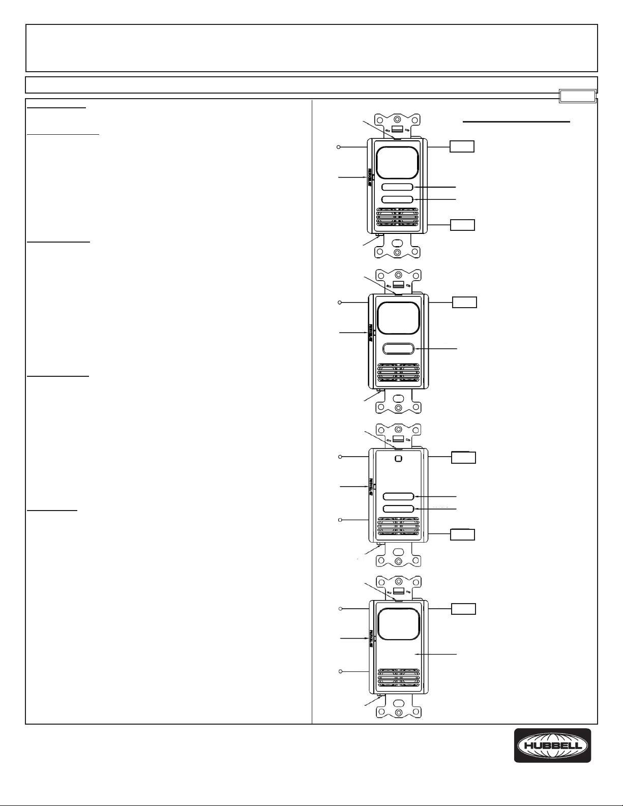
COVER RELEASE
CATCH
LINE CIRCUIT
BLACK
PHOTOCELL
PUSH BUTTON
GROUND
CONNECTION
COVER RELEASE
CATCH
LINE CIRCUIT
BLACK
PHOTOCELL
PUSH BUTTON
GROUND
CONNECTION
COVER RELEASE
CATCH
LINE CIRCUIT
BLACK
PHOTOCELL
PUSH BUTTON
NEUTRAL
WHITE
GROUND
CONNECTION
COVER RELEASE
CATCH
LINE CIRCUIT
BLACK
PHOTOCELL
PUSH BUTTON
NEUTRAL
WHITE
WIRING DIAGRAMS
RED
LOAD 1
BUTTON A
(TEST BUTTON)
BUTTON B
BLUE
LOAD 2
RED
LOAD
BUTTON A
(TEST BUTTON)
RED
LOAD 1
BUTTON A
(TEST BUTTON)
BUTTON B
BLUE
LOAD 2
RED
LOAD
(TEST BUTTON
LOCATED
UNDER COVER)
English
FIGURE 1
MULTI-TECH, DUAL
CIRCUIT, GROUND
CONNECTION
FIGURE 2
MULTI-TECH, SINGLE
CIRCUIT, GROUND
CONNECTION
FIGURE 3
ULTRASONIC, DUAL
CIRCUIT, NEUTRAL
CONNECTION
FIGURE 4
PASSIVE INFRARED,
SINGLE CIRCUIT, NO
BUTTON, NEUTRAL
CONNECTION
Wiring Device-Kellems
Hubbell Incorporated (Delaware)
Shelton, CT 06484
1-800-288-6000
www.hubbell-wiring.com
PD2611 Page 1 04/15
GROUND
CONNECTION
®
Page 2

MANUAL OVERRIDE
Press button(s) to toggle lights ON or OFF. Lights will remain in the last
state determined by the buttons while occupancy is detected. Sensor
will return to the programmed mode of operation when the sensor times
out. NOTE: Sensors with no buttons always operate in the Automatic
ON/Automatic OFF mode and cannot be manually turned off.
PHOTOCELL CONTROL
The photocell is used to detect if other light sources such as
sunlight, are sufcient to illuminate the space without turning on the
controlled lights. For Dual Circuit sensors, only Circuit B is
controlled by the photocell. The sensor is shipped from the factory
with the photocell control disabled. If use of the photocell is desired,
calibrate the photocell set point as follows:
1.With the light level at the desired level where the controlled lights
should be off, PRESS and RELEASE the photocell set button
using the end of a paper clip or small bladed screwdriver.
2.Step back from the sensor to avoid changing ambient light levels
in the room. During calibration the sensor will turn the lights OFF
then back ON.
3.After the calibration process, the sensor will return to its
programmed mode of operation. During occupancy, the sensor
will turn lighting OFF sixty (60) seconds after reaching or
exceeding the set point level. When the lighting level drops below
the set point level, the sensor will turn the lights ON.
ADJUSTMENTS
The following switch adjustments require that the sensor’s cover
be removed. Remove the cover by inserting a small blade screwdriver
into the catch at the top of the sensor and gently pry the cover off. Set
the adjustment switches as desired (see
CONFIGURATION
is all switches OFF. To re-install cover, place cover directly over the
sensor and align the cover’s four (4) catches with the recesses in the
sensor housing. Snap cover onto housing making sure that all catches
are securely in place.
CONFIGURATION SWITCH SETTINGS – BANK A
Switch 1 – Sensor Operation Relay 1 (Default – Manual ON/Automatic OFF)
Note: This switch is disabled for 2001 series vacancy sensors.
Programs the sensor for either Manual ON/Automatic OFF
operation or Automatic ON/Automatic OFF operation. When set to
Manual ON/Automatic OFF mode, lights are turned ON by
manually pressing the ON/OFF button. If the sensor times out and
turns the lights OFF in the Manual ON/Automatic OFF mode while the
space is still occupied, any motion detected within thirty (30) seconds
will automatically turn the lights back ON, without requiring the user to
press the ON button.
Switch 2 – Dual Circuit Relay 2 (Default – Manual ON/
Automatic OFF)
Note: This switch is disabled for 2001 series vacancy sensors.
Programs the sensor for either Manual ON/Automatic OFF
operation or Automatic ON/Automatic OFF operation. When set to
Manual ON/Automatic OFF mode, lights are turned ON by
manually pressing the ON/OFF button. If the sensor times out and
turns the lights OFF in the Manual ON/Automatic OFF mode while the
space is still occupied, any motion detected within thirty (30) seconds
will automatically turn the lights back ON, without requiring the user to
press the ON button.
SWITCH SETTINGS
section). Factory default
Switch 3 – Adaptive or Fixed Timer (Default – Adaptive)
Controls selection between Adaptive Timer Mode and Fixed Timer
Mode. In Adaptive Timer Mode, the sensor automatically self-adjusts
its timeout delay to optimize energy savings. The sensor will initialize
its timer value to eight (8) minutes. If the Bank B Timer Select 0 and
Timer Select 1 switches have been set to four (4) minutes, this will be
the smallest timer value used. In Fixed Timer Mode, the sensor’s selfadapting timer functions are disabled and the sensor’s timeout delay is
set according to the Bank B Timer Select 0 and Timer Select 1 switch
settings.
Switch 4 – Adaptive Reset (Default – Off)
The sensor is equipped with Hubbell patented self-adaptive IntelliDAPT® technology which automatically adjusts the sensor’s sensitivity and timer settings to optimize performance based on occupancy
patterns. The sensor constantly learns and adjusts appropriately. If the
learned settings need to be reset (e.g. when relocating sensor to another area), toggle the switch ON then OFF. The adaptive timer is reset
according to the Bank B Timer Select 0 and Timer Select 1 switches.
The adaptive sensitivity (both PIR and Ultrasonic as applicable) are
reset to
factory default. The photocell sensor settings are also reset to
factory default (disabled) such that the sensor will turn on the light(s) in
response to occupancy regardless of ambient light levels in the lighted
space. NOTE: Adaptive reset can also be achieved by pressing and
holding the photocell set button for ten (10) seconds.
Switch 5 – Relay Bypass (Default – Off)
If it is necessary to service the controlled circuits without de-energizing
them at the breaker panel (NOTE: this is not recommended as a standard procedure), perform the following steps:
1.With the lights ON, set the relay bypass switch to the ON
position.
2.Push the button(s) to turn the lights OFF.
3.Push the button(s) again to verify override (lights should not
come back on).
The relay bypass switch will now interrupt sensor operation,
preventing output(s) from turning ON again, regardless of
occupancy or pushbutton conditions. To return the sensor to
normal operation, ip the relay bypass switch to the OFF position.
To conrm sensor is operating normally, lights should now turn
ON and OFF when the button(s) are pressed.
CONFIGURATION SWITCH SETTINGS – BANK B
Switches 1 and 2 – Timer Settings (Default – 8 min)
Sets the length of time lights will remain ON after last motion is detected. The timeout value can be set to 4, 8, 16 or 30 minutes. See
Bank A – Switch 3 - Adaptive or Fixed Timer section for additional
information.
Switches 3 and 4 – Sensing Technology Enable/Disable (Default – Enable)
Enables or disables the occupancy sensing technologies used by the
sensor.
Switch 5 – Sensitivity (Default – High)
Sets the sensor’s initial Passive Infrared (PIR) and/or Ultrasonic sensitivity level. Sensitivity can be set to either High or Low.
Switch Bank A Function OFF (Default) ON
1 Sensor Operation Relay 1 Manual ON / Automatic OFF Automatic ON / Automatic OFF
2 Dual Circuit Relay 2 Manual ON / Automatic OFF Automatic ON / Automatic OFF
3 Timer Mode Adaptive Fixed
4 Adaptive Reset Enable Adaptation Restore Factory Defaults
5 Relay Bypass Normal Operation Relay Override
Switch Bank B Function OFF ON
1 Timer Select 0
2 Timer Select 1
Æ Å Å Æ
Å Å Æ Æ
Time 4 min 8 min 16 min 30 min
3 Passive Infrared Enabled Disabled
4 Ultrasonic Enabled Disabled
5 Sensitivity High Low
PD2611 Page 2 04/15
Page 3

H-MOSSMDMotion Switching System
Capteurs de mouvement à Ultrasonique / infrarouge passifs
Directives de montage et mode d'emploi
DESCRIPTION
Le H-MOSS
pour remplacer les commutateurs muraux existants.
SPÉCIFICATIONS
• Zone de couverture 93 m2 (modèles AP et AD)
• Zone de couverture 37m2 (modèle AU)
• Circuit simple ou double 120/277 VCA, 50/60 Hz
• Valeurs assignées : (chaque sortie séparément)
120 VCA – 800 W incandescent, 1000 W uorescent, 1/4 HP
277 VCA – 1800 W uorescent, 1/4 HP
• Temporisation réglable : 4-30 minutes, s’adapte à la présence
• Réglage du niveau lumineux (sortie du circuit B en version à
deux circuits) : 10 à 500 FC
• Homologué UL et cUL
PRÉCAUTIONS
ATTENTION - RISQUE DE CHOC ÉLECTRIQUE. Couper le courant au
niveau du panneau électrique avant de procéder au montage. Ne jamais
câbler des composants électriques dans un circuit sous tension.
Lire et bien comprendre toutes les directives avant de procéder au montage.
AVIS - Doit être installé par un électricien qualié conformément aux codes de
l'électricité nationaux et locaux et selon les directives suivantes.
AVIS - Pour usage à l'intérieur seulement.
ATTENTION - EMPLOYER UNIQUEMENT DES CONDUCTEURS EN
CUIVRE.
S’assurer que les valeurs assignées de ce dispositif conviennent à l’application
avant de l’installer. L'utilisation du dispositif dans des applications excédant
ses valeurs assignées ou pour lesquelles il n’a pas été conçu risque d'être non
sécuritaire et d'invalider la garantie du fabricant.
AVIS - Ne pas installer si le produit semble endommagé.
AVIS – Connecter à un câblage homologué 60 °C ou plus.
MONTAGE
1. Couper le courant au niveau du panneau électrique.
2. Retirer le vieux commutateur s’il y a lieu.
3. Câbler selon les illustrations des SCHÉMAS DE CÂBLAGE. Les gures 1
et 2 indiquent la méthode de câblage des capteurs avec une mise à la
terre (REMARQUE – Une mise à la terre able est requise pour assurer
le bon fonctionnement). Les gures 3 et 4 indiquent la méthode de
câblage des capteurs comportant un neutre.
4. Monter le capteur dans la boîte murale à l’aide des vis fournies.
5. Remettre sous tension le capteur et lui permettre de s'initialiser (jusqu'à
2 minutes).
6. Le capteur est réglé en usine an d’obtenir des économies d’énergie
optimales. S’il faut procéder à des réglages additionnels, consulter la
section RÉGLAGES.
7. S’il faut tenir compte de la lumière du jour, calibrer la cellule photoélec trique du capteur conformément à la section RÉGLAGE DE LA CELLULE
PHOTOÉLECTRIQUE.
8. Fixer une plaque murale du type « decorator » (non incluse).
MODE D’ESSAI
1. S’assurer que les lumière sont allumées (ON).
2. Enfoncer et maintenir le bouton ON/OFF. Les lumières passeront alterna tivement de OFF à ON. Relâcher le bouton ON/OFF.
• Pour les capteurs à deux circuits, enfoncer et maintenir le bouton ON/OFF
du circuit A.
• Pour les capteurs sans boutons, retirer le couvercle (consulter la section
RÉGLAGES) et enfoncer et maintenir le bouton d’essai.
3. Le capteur est alors en mode d’essai. (REMARQUE –En mode d’essai, le
capteur fonctionne en mode ON automatique/ OFF automatique). Quitter la
pièce; les lumières doivent s’éteindre après 5 secondes. Attendre 5 sec
ondes après la fermeture des lumières pour rentrer dans la pièce. En péné trant dans la pièce, les lumières s’allume à nouveau. Répéter ces étapes
au besoin pour s’assurer du bon fonctionnement du capteur et que la dé
tection du mouvement est adéquate. La DEL rouge et/ou verte clignote
pour indiquer respectivement la détection infrarouge passive ou
ultraso
sont très sensibles et peuvent requérir plus de 5 secondes sans mouvement
avant d’éteindre les lumières.
4.
Pour quitter le mode d’essai, enfoncer n’importe quel bouton. REMARQUE –
Le capteur quitte automatiquement le mode d’essai après soixante (60)
minutes.
MD
est un capteur de mouvements auto-adaptatif intelligent conçu
nique des mouvements. REMARQUE – Les capteurs ultrasoniques
FENTE D’OUVERTURE
DU COUVERCLE
CIRCUIT
DE LIGNE
NOIR
BOUTONPOUSSOIR
CELLULE
PHOTO
ÉLECTRIQUE
CONNEXION
À LA TERRE
FENTE D’OUVERTURE
DU COUVERCLE
CIRCUIT
DE LIGNE
NOIR
BOUTONPOUSSOIR
CELLULE
PHOTO
ÉLECTRIQUE
CONNEXION
À LA TERRE
FENTE D’OUVERTURE
DU COUVERCLE
CIRCUIT
DE LIGNE
NOIR
BOUTONPOUSSOIR
CELLULE
PHOTO
ÉLECTRIQUE
NEUTRE
BLANC
CONNEXION
À LA TERRE
FENTE D’OUVERTURE
DU COUVERCLE
CIRCUIT
DE LIGNE
NOIR
BOUTONPOUSSOIR
CELLULE
PHOTO
ÉLECTRIQUE
NEUTRE
BLANC
CONNEXION
À LA TERRE
SCHÉMAS DE CÂBLAGE
ROUGE
CHARGE 1
BOUTON A
(BOUTON D’ESSAI)
BOUTON B
BLEU
CHARGE 2
ROUGE
CHARGE
BOUTON A
(BOUTON D’ESSAI)
ROUGE
CHARGE 1
BOUTON A
(BOUTON D’ESSAI)
BOUTON B
BLEU
CHARGE 2
ROUGE
CHARGE
(BOUTON D’ESSAI
SOUS LE
COUVERCLE)
Français
FIGURE 1 –
MULTI-TECH,
DEUX CIRCUITS,
CONNEXION
À LA TERRE
FIGURE 2 –
MULTI-TECH, UN
CIRCUIT, CONNEXION
À LA TERRE
FIGURE 3 –
ULTRASONIQUE, DEUX
CIRCUITS, CONNEXION
AU NEUTRE
FIGURE 4 –
INFRAROUGE PASSIF,
UN CIRCUIT, SANS
BOUTON,
CONNEXION
AU NEUTRE
Wiring Device-Kellems
Hubbell Incorporated (Delaware)
Shelton, CT 06484
1-800-288-6000
www.hubbell-wiring.com
PD2611 Page 3 04/15
®
Page 4

ANNULATION DE PRIORITÉ MANUELLE
Appuyer sur le bouton pour allumer ou éteindre les lumières. Les lumières resteront dans la dernière position commandée par les boutons
pendant qu’il y a détection de mouvements. Le capteur revient au mode
programmé à la n de la temporisation du capteur. REMARQUE – Les
capteurs sans boutons fonctionnent toujours en mode ON automatique/
OFF automatique et ne peuvent être désactivés manuellement.
RÉGLAGE DE LA CELLULE PHOTOÉLECTRIQUE
La cellule photoélectrique sert à détecter si d'autres sources lumineuses
comme la lumière du soleil sufsent à éclairer la pièce sans allumer les
lumières. En ce qui concerne les capteurs à deux circuits, seul le circuit
B est commandé par la cellule photoélectrique. La commande photoélectrique du capteur est désactivée à la sortie de l'usine. Pour utiliser
la cellule photoélectrique, calibrer les points de consigne de la cellule
photoélectrique comme suit :
1. Lorsque l’intensité lumineuse atteint la valeur désirée et que les
luminaires sont éteints, APPUYER et RELÂCHER le bouton de
réglage de la cellule photoélectrique avec le bout d'un trombone
ou d'un petit tournevis à lame plate.
2. S'éloigner du capteur pour éviter d'inuencer l’intensité lumin
euse ambiante. Pendant le réglage, le capteur éteint puis allume
les lumières.
3. Une fois le calibrage terminé, le capteur passe au mode de fonc
tionnement programmé. En présence de mouvements, le
capteur éteint les lumières soixante (60) secondes après avoir
atteint ou dépassé la valeur de consigne. Lorsque le niveau de
lumière chute en deçà du point de consigne, le capteur allume
les lumières.
RÉGLAGES
Les réglages suivants exigent de retirer le couvercle du capteur. Enlever
le couvercle en introduisant un petit tournevis à lame plate dans la fente
dans le haut du capteur et tordre légèrement pour dégager le couvercle.
Régler les commutateurs au besoin (consulter la section CONFIGURA-
TION DES COMMUTATEURS). Par défaut, tous les commutateurs sont
réglés à OFF à l'usine. Pour remettre en place le couvercle, le mettre
directement sur le capteur et aligner les quatre (4) ergots avec les encastrements dans le bâti du capteur. Emboîter le couvercle sur le capteur en
s'assurant que tous les ergots sont bien encastrés.
CONFIGURATION DES COMMUTATEURS – GROUPE A
Commutateur 1 – Relais 1 fonctionnement du capteur (par défaut
–ON manuel/OFF automatique)
Remarque - Ce commutateur est désactivé en ce qui concerne les
capteurs de mouvements de la série 2001.
Programme le capteur pour un fonctionnement ON manuel/OFF automatique ou ON automatique/OFF automatique. En mode ON manuel/
OFF automatique, les lumières s'allument en appuyant manuellement
sur le bouton ON/OFF. Lorsque la temporisation du capteur arrive à
terme, provoquant la fermeture des lumières en mode ON manuel/OFF
automatique alors que la pièce est toujours occupée, la détection de tout
mouvement dans les trente (30) secondes allume automatiquement les
lumières sans que l'utilisateur ait à appuyer sur le bouton ON.
Commutateur 2 – Relais 2 à deux circuits (par défaut –ON manuel/
OFF automatique)
Remarque - Ce commutateur est désactivé en ce qui concerne les
capteurs de mouvements de la série 2001.
Programme le capteur pour un fonctionnement ON manuel/OFF automatique ou ON automatique/OFF automatique. En mode ON manuel/
OFF automatique, les lumières s'allument en appuyant manuellement
sur le bouton ON/OFF. Lorsque la temporisation du capteur arrive à
terme, provoquant la fermeture des lumières en mode ON manuel/OFF
automatique alors que la pièce est toujours occupée, la détection de tout
mouvement dans les trente (30) secondes allume automatiquement les
lumières sans que l'utilisateur ait à appuyer sur le bouton ON.
Commutateur 3 – Capteur adaptatif ou xe (par défaut– adaptatif)
Permet de choisir entre les modes adaptatif et xe du capteur. En mode
adaptatif, le capteur ajuste automatiquement sa temporisation de façon à
optimiser les économies d'énergie. Le capteur initialise sa valeur de temporisation à huit (8) minutes. Lorsque les commutateurs Choix de la temporisation 0 et Choix de la temporisation 1 du groupe B ont été réglés à
quatre (4) minutes, cela représente la plus petite valeur de temporisation
utilisée. En mode de temporisation xe, les fonctions auto-adaptatives du
capteur sont désactivées et la temporisation du capteur correspond aux
réglages des commutateurs Choix de la temporisation 0 et Choix de la
temporisation 1 du groupe B.
Commutateur 4 – Retour à la fonction adaptative (par défaut – Off)
Le capteur intègre la technologie auto-adaptative brevetée IntelliDAPTMD de Hubbell qui ajuste automatiquement la sensibilité et les réglages
du capteur en vue d’optimiser la performance en fonction de l’occupation.
Le capteur s’adapte constamment et se règle en conséquence. Lorsque
les réglages appris doivent être modiés (ex. lors de la relocalisation du
capteur à un autre endroit), faire basculer le commutateur à ON puis à
OFF. La temporisation adaptative est réinitialisée en fonction des commutateurs Choix de la temporisation 0 et Choix de la temporisation 1 du
groupe B. La sensibilité adaptative (infrarouge passive et ultrasonique
selon les cas) est ramenée à la valeur par défaut de l'usine. Les réglages
du capteur à cellule photoélectrique sont aussi ramenés aux valeurs
par défaut de l'usine (désactivées) de sorte que le capteur allumera les
lumières en présence de mouvements, peu importe l’intensité lumineuse
à l'intérieur de la pièce. REMARQUE - Il est aussi possible de réinitialiser
la fonction adaptative en appuyant et en maintenant le bouton de réglage
de la cellule photoélectrique pendant dix (10) secondes.
Commutateur 5 – Dérivation du relais (par défaut – Off)
S'il s'avère nécessaire d’effectuer des travaux sur les circuits commandés sans les mettre hors tension à partir du panneau électrique
(REMARQUE - Cela n'est pas recommandable comme processus
standard), franchir les étapes suivantes :
1. Lorsque les lumières sont allumées, mettre le commutateur de dériva
tion du relais à ON.
2. Enfoncer le bouton pour éteindre les lumières.
3. Enfoncer à nouveau le bouton pour vérier l'annulation de priorité (les
lumières ne doivent pas se rallumer). Le commutateur de dérivation
du relais interrompra le fonctionnement
du capteur, prévenant ainsi
que les charges s'allument à nou veau, peu importe qu’il y ait détec
tion de mouvements ou la position du bouton-poussoir. Pour remettre le
capteur en position normale de fonctionnement, basculer le commu
tateur de dérivation du relais à OFF. Pour conrmer le fonctionnement
normal du capteur, les lumières doivent s'allumer et s'éteindre lorsqu'on
appuie sur les boutons.
CONFIGURATION DES COMMUTATEURS – GROUPE B
Commutateurs 1 et 2 – Réglages de la temporisation (par défaut – 8
min)
Règle le temps pendant lequel les lumières restent allumées après la
détection du dernier mouvement. Le temps d'arrêt peut être réglé à 4,
8, 16 ou 30 minutes. Consulter la section Groupe A – Commutateur 3 Temporisation adaptative ou xe pour plus d'information.
Commutateurs 3 et 4 –Technologie de détection activée/désactivée
(par défaut– activée)
Active ou désactive les technologies de détection de mouvements utilisée par le capteur.
Commutateur 5 – Sensibilité (par défaut– élevée)
Règle la sensibilité initiale du capteur infrarouge passif et/ou ultrasonique. Réglages possibles : élevée ou faible.
Commutateurs
Groupe A
1
2 Relais 2 à deux circuits ON manuel / OFF automatique ON automatique / OFF automatique
3 Mode de temporisation Adaptative Fixe
4 Retour à la fonction adaptative Activer l’adaptation Retour aux valeurs par défaut de l’usine
5 Dérivation du relais Fonctionnement normal Annulation de priorité du relais
Commutateurs
Groupe B
1 Choix de la temporisation 0
2 Choix de la temporisation 1
Temporisation 4 min 8 min 16 min
3 Infrarouge passive Activé Désactivé
4 Ultrasonique Activé Désactivé
5 Sensibilité Élevée Faible
Fonction OFF (par défaut) ON
Relais 1 à fonctionnement
du capteur
Fonction
PD2611 Page 4 04/15
ON manuel / OFF automatique ON automatique / OFF automatique
OFF ON
Æ Å Å Æ
Å Å Æ Æ
30 min
Page 5

H-MOSSMRMotion Switching System
Detectores de movimiento por Ultrasonic / infrarrojos pasivos
Instrucciones de instalación y de uso
DESCRIPCIÓN
El H-MOSSMR es un detector de movimiento auto-adaptable inteligente diseñado para reemplazar los interruptores de pared existentes.
ESPECIFICACIONESS
• Área de cobertura de 93 m2 (1000 p.c.) (Modelos: AP y AD)
• Área de cobertura de 37 m2 (400 p. c.) (Modelos: AU)
• Operación de Circuito sencillo o doble 120/277 V~, 50/60 Hz
• Valores eléctricos nominales: (Cada salida por separado)
120 V~ – 800 W Incandescente, Balasto de 1000 W, 1/4 HP
277 V~ – Balasto de 1800 W, 1/4 HP
• Temporización ajustable: 4-30 minutos, se adapta a la presencia
• Ajuste del nivel luminoso (Salida del circuito B en versiones de circuitos
dobles): 10 a 500FC
• Homologado UL, cUL
PRECAUCIONES
¡CUIDADO! - RIESGO DE ELECTROCUCIÓN. Desconectar la corriente antes
de la instalación. No conectar nunca componentes eléctricos en un circuito
energizado.
Leer y comprender todas las instrucciones antes de comenzar la instalación.
AVISO - Para ser instalado por un electricista calicado, de acuerdo con los
códigos eléctricos nacionales y locales y siguiendo estas instrucciones.
AVISO - Para uso en interiores únicamente.
¡CUIDADO! - USAR SOLAMENTE CONDUCTORES DE COBRE
Conrmar que las características nominales sean las adecuadas para la
aplicación antes de la instalación. El uso del dispositivo en aplicaciones más
de los valores nominales especicados o en aplicaciones distintas a aquellas
indicadas puede crear condiciones inseguras y anular la garantía del fabricante.
AVISO - No instalar el producto si parece estar dañado.
AVISO - Conectar a un cableado homologado a 60°C o más.
INSTALACIÓN
1. Apagar la corriente en la caja de circuitos.
2. Retirar el interruptor viejo, si es el caso.
3. Alambre como se muestra en la sección de DIAGRAMAS DE CABLEA
DO. Las Figuras 1 y 2 muestran el método de cableado para sensores
con puesta a tierra (NOTA: Se necesita un suelo conable para una oper-
ación adecuada). Las Figuras 3 y 4 muestran el método de cableado
para sensores con un neutro.
4. Instalar el sensor en una caja mural utilizando los tornillos de montaje
provistos.
5. Restaurar la corriente en el sensor para y dejar que se inicialice (hasta 2
minutos).
6. El sensor ha sido congurado en fábrica para proveer un mayor ahorro
de energía. Si se necesitan ajustes adicionales, ver la sección ADJUSTES.
7. Si hay que tomar en consideración la luz del día, ajuste las fotoceldas del
sensor, como se describe en la sección CONTROL DE FOTOCELDAS.
8. Instalar una placa mural decorativa (ni incluida).
MODO DE PRUEBA
1. Asegurarse de que las luces estén encendidas.
2. Presionar y mantener presionado el botón ON/OFF. Las luces alternarán
entre OFF y ON. Soltar el botón ON/OFF.
• Para sensores de doble circuito, presionar y mantener presionado el
botón ON/OFF para circuitos A.
• Para sensores sin botón, retirar la tapa (ver la sección ADJUSTES) y
presionar y mantener presionado el botón de prueba.
3. El sensor está ahora en modo de prueba (NOTA: Cuando el sensor
está en modo de prueba, éste funcionará en modo ON/automático/ OFF
automático). Salir del recinto; las luces deberán apagarse después de
5 segundos. Esperar 5 segundos después de que se apaguen antes de
volver a entrar al recinto. Volver a entrar al recinto, las luces se
encenderán de nuevo. Repetir estas etapas las veces que sean
necesarias para conrmar que el sensor está funcionando y detectando en
el área deseada. El DEL rojo y/o verde del sensor parpadeará para indicar
respectivamente la detección infrarroja pasiva (PIR) o el ultrasonido de los
movimientos. NOTA: Los sensores con tecnología ultrasónica pueden ser
muy sensibles y pueden requerir más de 5 segundos de ausencia de
movimiento antes de apagar las luces.
4. Para salir del modo de prueba, presionar cualquier botón. NOTA: El
sensor saldrá automáticamente del modo de prueba después de sesenta
(60) minutos.
allá
PESTAÑA DE
APERTURA DE TAPA
CIRCUITO
DE LÍNEA
NEGRO
BOTÓN
PULSADOR DE
FOTOCELDA
PUESTA A
TIERRA
PESTAÑA DE
APERTURA DE TAPA
CIRCUITO
DE LÍNEA
NEGRO
BOTÓN
PULSADOR DE
FOTOCELDA
PUESTA A
TIERRA
PESTAÑA DE
APERTURA DE TAPA
CIRCUITO
DE LÍNEA
NEGRO
BOTÓN
PULSADOR DE
FOTOCELDA
NEUTRO
BLANCO
PUESTA A
TIERRA
PESTAÑA DE
APERTURA DE TAPA
CIRCUITO
DE LÍNEA
NEGRO
BOTÓN
PULSADOR DE
FOTOCELDA
NEUTRO
BLANCO
DIAGRAMAS DE CABLEADO
ROJO
CARGA 1
FIGURA 1 –
BOTÓN A (BOTÓN
DE PRUEBA)
BOTÓN B
AZUL
CARGA 2
ROJO
CARGA
BOTÓN A (BOTÓN
DE PRUEBA)
ROJO
CARGA 1
BOTÓN A (BOTÓN
DE PRUEBA)
BOTÓN B
AZUL
CARGA 2
ROJO
CARGA
(BOTÓN DE
PRUEBA BAJO
LA TAPA)
MULTI-TECH,
CIRCUITO DOBLE,
PUESTA A TIERRA
FIGURA 2 –
MULTI-TECH, CIRCUITO
SENCILLO, PUESTA A
TIERRA
FIGURA 3 –
ULTRASÓNICO,
CIRCUITO DOBLE,
CONEXIÓN NEUTRA
FIGURA 4 –
INFRARROJO PASIVO,
CIRCUITO SENCILLI,
SIN BOTÓN, CONEXIÓN
NEUTRA
Español
Wiring Device-Kellems
Hubbell Incorporated (Delaware)
Shelton, CT 06484
1-800-288-6000
www.hubbell-wiring.com
PD2611 Page 5 04/15
PUESTA A
TIERRA
®
Page 6

ANULACIÓN MANUAL
Presionar el botón para encender o apagar las luces. Las luces
permanecerán en el último estado determinado por los botones
cuando se detecte presencia. El sensor volverá al modo programado de
operación cuando el sensor llegue al nal de la temporización. NOTA: Los
sensores sin botones funcionarán siempre en modo ON/automático/ OFF
automático y no podrán ser apagados manualmente.
CONTROL DE FOTOCELDA
La fotocelda se usa para detectar si otras fuentes de iluminación como la
luz solar, son sucientes para iluminar el espacio son encender las luces
controladas. Para los sensores con circuitos dobles, sólo el circuito B es
controlado por la fotocelda. El sensor es enviado de fábrica con el
control de la fotocelda desactivado. Si se desea utilizar la fotocelda, ajustar
el punto de referencia de la fotocelda de la siguiente manera:
1. Con el nivel de iluminación en el nivel deseado en que las luces
controladas deben estar apagadas, PRESIONAR y SOLTAR el botón
de ajuste de la fotocelda utilizando el extremo un clip para papel o un
destornillador de punta pequeña.
2. Alejarse del sensor para evitar cambiar los niveles de la iluminación
ambiente en el recinto. Durante el ajuste el sensor apagará las luces
y las volverá a encender.
3. Después del proceso de ajuste, el sensor volverá a su modo de
operación programado. En presencia de movimientos, el sensor
apagará las luces durante sesenta (60) segundos después de alcanzar
o exceder el nivel del punto de referencia. Cuando el nivel de
iluminación llegue a estar debajo del nivel del punto de referencia, el
sensor encenderá las luces.
AJUSTES
Los siguientes ajustes de interruptores requieren que la tapa del sensor sea
retirada. Retirar la tapa insertando un destornillador de punta
pequeña dentro de la ranura en la parte superior del sensor y hacer una
ligera palanca para quitar la tapa. Ajustar los interruptores como desee (ver
la sección AJUSTES DE INTERRUPTORES DE CONFIGURACIÓN). La
conguración por defecto de fábrica es con todos los
interruptores en OFF. Para volver a instalar la tapa, colocar la tapa directamente sobre el sensor y alinear las cuatro (4) pestañas del sensor con los
oricios en la caja protectora del sensor. Presionar la tapa sobre la caja
protectora y asegurarse que todas las pestañas estén bien colocadas en su
sitio.
AJUSTES DE LOS INTERRUPTORES DE CONFIGURACIÓN – GRUPO A
Interruptor 1 – Operación del sensor Relevador 1 (Por defecto –ON
manual / OFF automático)
Nota: Este interruptor está desactivado en los detectores de
movimiento de la serie 2001.
Programa el sensor para ya sea para operación ON manual/ OFF
automático o ON automático/ OFF automático. Cuando se ajusta en modo
ON manual/ OFF automático, las luces se encienden manualmente presionando el botón ON/OFF. Si la temporización llega a su n y apaga la luz
en modo ON manual/ OFF automático cuando el recito está aún ocupado,
cualquier movimiento detectado dentro de los treinta (30) segundos encenderá automáticamente las luces, sin que el usuario tenga que presionar
el botón ON.
Interruptor 2 – Relevador de doble circuito 2 (Por defecto –ON manual
/ OFF automático)
Nota: Este interruptor está desactivado en los detectores de
movimiento de la serie 2001.
Programa el sensor para ya sea para operación ON manual/ OFF
automático o ON automático/ OFF automático. Cuando se ajusta en modo
ON manual/ OFF automático, las luces se encienden manualmente presionando el botón ON/OFF. Si la temporización llega a su n y apaga la luz
en modo ON manual/ OFF automático cuando el recito está aún ocupado,
cualquier movimiento detectado dentro de los treinta (30) segundos encenderá automáticamente las luces, sin que el usuario tenga que presionar
el botón ON.
Interruptor 3 – Temporizador adaptivo o jo (Por defecto – adaptivo)
Controla la selección entre modo temporizador adaptivo y modo de temporizador jo. En el modo adaptivo, el sensor ajusta automáticamente su
temporización con el n de optimizar el ahorro de energía. El sensor inicializará su valor de temporización a ocho (8) minutos. Si los interruptores de
Selección de temporización 0 y Selección de temporización 1 del grupo B
han sido ajustados a cuatro (4) minutos, este será el valor más bajo usado.
En modo de temporización ja, las funciones auto-adaptivas del sensor son
desactivadas y la temporización del captor corresponde a los ajustes de los
interruptores Selección de temporización 0 y la Sección de temporización
del grupo B.
Interruptor 4 – Reinicialización adaptiva (Por defecto – Off)
El sensor está equipado con tecnología adaptiva patentada IntelliDAPT®
de Hubbell que ajusta automáticamente la sensibilidad del sensor y los
ajustes de temporización para optimizar el rendimiento basado en patrones
de ocupación. El sensor aprende
constantemente y se ajusta en consecuencia. Si se necesita reinicializar los
ajustes aprendidos (por ejemplo, al reubicar el sensor a otra área), colocar
el interruptor a ON y OFF. El temporizador adaptivo se
reinicializa de acuerdo con los interruptores de Selección de
temporización 0 y Selección de temporización 1 del grupo B. La sensibilidad adaptiva ( tanto PIR como ultrasónico según el caso) se reinicializa a
los valores por defecto de fábrica. Los ajustes del sensor de la
fotocelda se reinicializan a los valores por defecto de fábrica (desactivado)
para que los sensores enciendan las luces en presencia de movimientos sin importar la intensidad luminosa en el interior del recinto. NOTA:
También se puede lograr la Reinicialización adaptativa presionando y
manteniendo presionado el boto de ajuste de la fotocelda durante diez (10)
segundos.
Interruptor 5 – Derivación del relé (Por defecto – Off)
Si es necesario hacer mantenimiento a los circuitos controlados sin quitarles la corriente en la caja de circuitos (NOTA: esto no se recomienda como
un procedimiento estándar), efectuar los siguientes pasos:
1. Con las luces encendidas, colocar el interruptor de derivación de relé
en la posición ON.
2. Presionar el botón para apagar las luces.
3. Presionar el botón otra vez para vericar la anulación manual (las
luces no deberían encenderse). Ahora el interruptor de derivación de
relé interrumpirá la operación del sensor, impidiendo que las cargas
se enciendan de nuevo, sin importar que haya detección de
movimientos o la posición del botón pulsador. Para restaurar la
operación normal del sensor, volver a colocar el interruptor de
derivación de relé en posición OFF. Para conrmar que el sensor
esté operando normalmente, las luces deben encenderse y apagarse
al presionar los botones.
CONFIGURACIÓN DE LOS INTERRUPTORES – GRUPO B
Interruptores 1 y 2 – Ajustes de temporización (Por defecto – 8 min.)
Ajusta el tiempo en que las luces permanecerán encendidas después
de que se detecte el último movimiento. El valor de temporización puede
ajustarse en 4, 8, 16 ó 30 minutos. Ver sección Grupo A – Interruptor 3 –
Temporizador adaptivo y jo para información adicional.
Interruptores 3 and 4 – Tecnología de detección activada/desactivada
(Por defecto – Activado)
Activa y desactiva las tecnologías de detección de movimientos usadas por
el sensor.
Interruptor 5 – Sensibilidad (Por defecto – Alta)
Ajusta el nivel de sensibilidad inicial del sensor infrarrojo pasivo (PIR) y/o
ultrasónico. La sensibilidad puede ajustarse en alto o bajo.
HUBBELL DE MEXICO garantiza este producto, de estar libre de defectos en materiales y mano de
obra por un período de un año a partir de la fecha de su compra. HUBBELL reparará o reemplazará a
su juicio el producto en un plazo de 60 días. Esta garantía no cubre desgastes por uso normal o daños
ocasionados por accidente, mal uso, abuso o negligencia. El vendedor no otorga otras garantías salvo
lo expresado arriba y excluye expresamente daños incidentales o consecuenciales. ESTA GARANTÍA
ES VÁLIDA SÓLO EN MÉXICO.
HUBBELL DE MÉXlCO, S.A. DE C.V.
México, 03200 D.F. Tel. (55) 9151-9999
Av. Insurgentes Sur # 1228 Piso 8, Col. Tlacoquemecatl del Valle
Interruptores Grupo A Función OFF (Por defecto) ON
1
2 Relevador de doble circuito 2 ON manual / OFF automático ON automático/ OFF automático
3 Modo de temporización Adaptivo Fijo
4 Reinicialización adaptiva Adaptación Restaurar valores de fábrica por defecto
5 Derivación del relé Operación normal Anulación manual de relé
Interruptores Grupo B Función
1 Selección de temporización 0
2 Selección de temporización 1
3 Infrarrojo Activado Desactivado
4 Ultrasónico Activado Desactivado
5 Sensibilidad Alto Bajo
Operación del sensor
Relevador 1
ON manual / OFF automático ON automático/ OFF automático
OFF ON
Æ Å Å Æ
Å Å Æ Æ
Tiempo 4 min 8 min 16 min
PD2611 Page6 04/15
30 min
 Loading...