

Hubbell GX200, GX250, G250P, GX200P Installation & Operation Manual

WATER HEATERS SINCE 1920
Intuitive · Reliable · Efficient
INSTALLATION &
OPERATION MANUAL
Hubbell Model
GX200 / GX200P
GX250 / G250P
(nergy 6tar and 64$40D &erti¿ed
/oZ 12[
on 0odels *; / *;3
To avoid product damage, personal injury, or even
possible death, carefully read, understand, and
follow all the instructions in the Installation and
the Operation manuals before installing this
product. Improper installation, adjustment, alteration, or
maintenance can cause injury, loss of life, and/or property
damage. This water heater should be installed and serviced
by a qualified technician. The lack of proper service can
result in a dangerous condition.
This manual contains safety information, installation instructions,
and maintenance procedures. It must be left with the homeowner
or placed near the water heater in a noncombustible place. The
homeowner should retain this manual for future reference.
WARNING
If the information in these instructions is not followed
exactly, a fire or explosion could result causing
property damage, personal injury, or death.
— Do not store or use gasoline or other flammable
vapors and liquids in the vicinity of this or any
other appliance.
WHAT TO DO IF YOU SMELL GAS
!
Do not try to light any appliance.
!
Do not touch any electrical switch; do not use
any phone in your building.
!
Immediately call your gas supplier from a
neighbor’s phone. Follow the gas supplier’s
instructions.
!
If you cannot reach your gas supplier, call the
fire department.
— Installation and service must be performed by
a qualified installer, service agency, or the gas
supplier.
AVERTISSEMENT
Assurez-vous de bien suivre les instructions données
dans cette notice pour réduire au minimum le
risque d’incendie ou d’explosion ou pour éviter tout
dommage matériel, toute blessure ou la mort.
— Ne pas entreposer ni utiliser d’essence ou
ni d’autres vapeurs ou liquides inflammables
à proximité de cet appareil ou de tout autre
appareil.
QUE FAIRE SI VOUS SENTEZ UNE ODEUR DE GAZ
"
Ne pas tenter d’allumer d’appareil.
"
Ne touchez à aucun interrupteur; ne pas vous
servir des téléphones se trouvant dans
le bâtiment.
"
Appelez immédiatement votre fournisseur de gaz
depuis un voisin. Suivez les instructions
du fournisseur.
"
Si vous ne pouvez rejoindre le fournisseur,
appelez le service des incendies.
— L’installation et l’entretien doivent être assurés
par un installateur ou un service d’entretien
qualifié ou par le fournisseur de gaz.
Due to Hubbell’s policy of continuous product
improvement and technology, the design and/or technical
speci¿cations are subMect to change Zithout notice
Serial Number: ___________________________________
Date of Installation: ___ / ___ / ______


TABLE OF CONTENTS
Table of Contents
TABLE OF CONTENTS. . . . . . . . . . . . . . . . . . . . . 3
ITEMS SHIPPED WITH WATER HEATER . . . . . . 4
SAFETY . . . . . . . . . . . . . . . . . . . . . . . . . . . . . . . . .5
Safety Icon Nomenclature . . . . . . . . . . . . . . . . . . . . . . 6
Personal Protection . . . . . . . . . . . . . . . . . . . . . . . . . 6
Prohibited Actions. . . . . . . . . . . . . . . . . . . . . . . . . . . 6
Hazard Avoidance . . . . . . . . . . . . . . . . . . . . . . . . . . 6
Operation and Installation Warnings . . . . . . . . . . . . . . 6
TECHNICAL SPECIFICATIONS . . . . . . . . . . . . .10
SPECIFICATIONS (NOMENCLATURE) . . . . . . .12
DIMENSIONAL SPECIFICATIONS . . . . . . . . . . .13
QUICK REFERENCE INSTALLATION GUIDE . .14
PREPARATION BEFORE INSTALLATION. . . . . 16
Selecting an Installation Site . . . . . . . . . . . . . . . . . . . 16
High Elevation Installations . . . . . . . . . . . . . . . . . . 17
Water Quality . . . . . . . . . . . . . . . . . . . . . . . . . . . . . 17
WALL MOUNTING. . . . . . . . . . . . . . . . . . . . . . . .19
Mounting Block Installation Method. . . . . . . . . . . . . . 19
Plywood Installation Method . . . . . . . . . . . . . . . . . . . 19
ADJUSTING THE CO2LEVEL. . . . . . . . . . . . . . .39
Control Panel. . . . . . . . . . . . . . . . . . . . . . . . . . . . . . . 41
OPERATION . . . . . . . . . . . . . . . . . . . . . . . . . . . .41
Display Icons . . . . . . . . . . . . . . . . . . . . . . . . . . . . . 42
Setting the Time . . . . . . . . . . . . . . . . . . . . . . . . . . . . 43
Adjusting the Water Temperature . . . . . . . . . . . . . . . 44
Customer Screens. . . . . . . . . . . . . . . . . . . . . . . . . . . 45
Domestic Heating Mode. . . . . . . . . . . . . . . . . . . . . 45
Programming ON/OFF Run Times. . . . . . . . . . . . . 45
WATER HEATER PROGRAMMING SECTION. . 45
Recirculation Setup . . . . . . . . . . . . . . . . . . . . . . . . . . 46
Cascading (Daisy Chain). . . . . . . . . . . . . . . . . . . . . . 47
Technician Screens . . . . . . . . . . . . . . . . . . . . . . . . . . 48
Pressure Booster (pump models only . . . . . . . . . . 48
Fast Start Selection . . . . . . . . . . . . . . . . . . . . . . . . 48
Flow Booster . . . . . . . . . . . . . . . . . . . . . . . . . . . . . 49
Blower Ramp Selection . . . . . . . . . . . . . . . . . . . . . 49
Flow Control Selection . . . . . . . . . . . . . . . . . . . . . . 50
Fuel Type Selection . . . . . . . . . . . . . . . . . . . . . . . . 50
Blower Override . . . . . . . . . . . . . . . . . . . . . . . . . . . 50
Diagnostic Code and Error Log Selection . . . . . . . 51
Diagnostic Code and Error Log Selection . . . . . . . 52
Adjusting CO2 Levels Selection . . . . . . . . . . . . . . . 52
Commercial Heating Selection. . . . . . . . . . . . . . . . 52
GAS CONNECTION. . . . . . . . . . . . . . . . . . . . . . .20
GAS PIPE SIZING TABLES . . . . . . . . . . . . . . . .21
Gas Pipe Sizing. . . . . . . . . . . . . . . . . . . . . . . . . . . . . 21
Natural Gas Pipe Sizing . . . . . . . . . . . . . . . . . . . . . 21
LP Gas Pipe Sizing . . . . . . . . . . . . . . . . . . . . . . . . 21
COMBUSTION (FRESH) AIR INLET EXHAUST
OUTLET CONNECTIONS . . . . . . . . . . . . . . . . . .22
VENTING . . . . . . . . . . . . . . . . . . . . . . . . . . . . . . .24
Combustion (All) Air From the Outdoors . . . . . . . . 24
Outdoor Air . . . . . . . . . . . . . . . . . . . . . . . . . . . . . 24
Two Openings or Ducts. . . . . . . . . . . . . . . . . . . . 24
Size of Openings. . . . . . . . . . . . . . . . . . . . . . . . . 24
Attic Combustion Air . . . . . . . . . . . . . . . . . . . . . . 24
Under-fl oor Combustion Air. . . . . . . . . . . . . . . . . 24
Opening Requirements . . . . . . . . . . . . . . . . . . . . 24
Combustion (All) Air From Inside the Building . . . . 26
Required Volume. . . . . . . . . . . . . . . . . . . . . . . . . 26
Confi ned Space. . . . . . . . . . . . . . . . . . . . . . . . . . 26
Unusually Tight Construction . . . . . . . . . . . . . . . 26
Power Vent Installation Examples . . . . . . . . . . . . . 26
INSTAL HOT WATER LINES. . . . . . . . . . . . . . . . 27
INSTAL COLD WATER LINES . . . . . . . . . . . . . .28
INSTALL CONDENSATE DRAIN . . . . . . . . . . . .29
CONNECT ELECTRICAL POWER / INITIAL
STARTUP. . . . . . . . . . . . . . . . . . . . . . . . . . . . . . .30
MULTIPLE UNITS . . . . . . . . . . . . . . . . . . . . . . . . 31
MEASURING GAS PRESSURE . . . . . . . . . . . . .36
PROPANE (LPG) CONVERSION . . . . . . . . . . . . 37
MAINTENANCE. . . . . . . . . . . . . . . . . . . . . . . . . . 53
Cleaning the Inlet Water Y-Strainer . . . . . . . . . . . . . . 54
Draining the Water Heater. . . . . . . . . . . . . . . . . . . . . 54
Filling the Water Heater. . . . . . . . . . . . . . . . . . . . . . . 55
TROUBLESHOOTING CHART . . . . . . . . . . . . . .55
WIRING DIAGRAM . . . . . . . . . . . . . . . . . . . . . . .57
COMMERCIAL OPTIONS . . . . . . . . . . . . . . . . . .58
Commercial Option #1 . . . . . . . . . . . . . . . . . . . . . . 59
Commercial Option #2 . . . . . . . . . . . . . . . . . . . . . . 59
Commercial Option #3 . . . . . . . . . . . . . . . . . . . . . . 59
Commercial Option #4 . . . . . . . . . . . . . . . . . . . . . . 59
Commercial Option #5 . . . . . . . . . . . . . . . . . . . . . . 59
Commercial Option #6 . . . . . . . . . . . . . . . . . . . . . . 59
OPERATIONAL DIAGRAM . . . . . . . . . . . . . . . . .59
WARRANTY. . . . . . . . . . . . . . . . . . . . . . . . . . . . .60
General . . . . . . . . . . . . . . . . . . . . . . . . . . . . . . . . . . . 61
Effective Start Date . . . . . . . . . . . . . . . . . . . . . . . . . . 61
Heat Exchanger Coil . . . . . . . . . . . . . . . . . . . . . . . . . 61
All other Parts and Components . . . . . . . . . . . . . . . . 61
Labor . . . . . . . . . . . . . . . . . . . . . . . . . . . . . . . . . . . . . 61
Shipping Costs . . . . . . . . . . . . . . . . . . . . . . . . . . . . . 61
Defi nition of Potable Water . . . . . . . . . . . . . . . . . . . . 61
WARRANTY. . . . . . . . . . . . . . . . . . . . . . . . . . . . .61
Not Covered by this Warranty . . . . . . . . . . . . . . . . . . 62
Warranty Limitations . . . . . . . . . . . . . . . . . . . . . . . . . 62
How to Make a Claim . . . . . . . . . . . . . . . . . . . . . . . . 62
Requirements for the State of Massachusetts . . . . . 63
Notice Before Installation . . . . . . . . . . . . . . . . . . . . 63
NOTES . . . . . . . . . . . . . . . . . . . . . . . . . . . . . . . . .64
3

ITEMS SHIPPED WITH WATER HEATER
The following items are shipped with the water heater;
upper mounting bracket (1), condensate
Operator’s manual (3), communication cable (4),
(5), and tee fitting (6).
hose (2),
O-rings
IMPORTANT
Condensate drain hose(2) has zip ties to keep
loop. Do not undo or cut these zip ties
4

WARNING
To avoid product damage, personal injury, or even
possible death, carefully read, understand, and
follow all the instructions in the Installation and
Operation manual and on the water heater before
installation, operation, or service.
Hubbell cannot anticipate every circumstance that might
involve a potential hazard and our warnings are, therefore, not
all-inclusive. Proper installation, operation, and service is your
responsibility.
You must be satisfied that the operation and settings of the
water heater are safe for you and for others.
Pour éviter un dommage au produit, une blessure personnelle
ou même la mort, lire avec soin, comprendre et suivre toutes
les instructions dans le manuel d'installation et de fonctionnement et sur le chauffe-eau avant l'installation, le fonctionnement ou l'entretien.
Hubbell ne peut pas prévoir toutes les circonstances qui
pourraient impliquer un danger potentiel et par conséquent,
nos avertissements ne comprennent pas tout. L'installation, le
fonctionnement et l'entretien correct sont votre
responsabilité.
Vous devez être certain que le fonctionnement et les réglages
du chauffe-eau sont sécuritaires pour vous et pour les autres.
IGT-LBL-0001-01
SAFETY
Hazards are identifi ed by the “Safety Alert Symbol”
and followed by a signal word such as “DANGER”,
“WARNING”, or “CAUTION”.
DANGER
Indicates an imminently hazardous situation which, if not avoided,
will result in death or serious injury. This signal word is limited to
the most extreme situations.
WARNING
Indicates a potentially hazardous situation which, if not avoided,
could result in death or serious injury.
CAUTION
Indicates a potentially hazardous situation which, if not avoided,
may result in minor or moderate injury.
Safety Alert Symbols
This is the safety alert symbol. It is used to alert
you to potential personal injury hazards. Obey
all safety messages that follow this symbol to
avoid possible injury or death.
This manual contains DANGERS, SAFETY
INSTRUCTIONS, CAUTIONS, IMPORTANT NOTICES,
and NOTES which must be followed to prevent the
possibility of improper service, damage to the equipment,
personal injury, or death. The following key words call the
readers’ attention to potential hazards.
NOTICE
Indicates that equipment or property damage can result if
instructions are not followed.
SAFETY
INSTRUCTIONS
Safety instructions (or equivalent) signs indicate specific safetyrelated instructions or procedures.
NOTE: Contains additional information important
to a procedure.
IMPORTANT
Indicates that equipment or property damage can
result if instructions are not followed.
NOTE: Provides additional information that is
helpful for installation or operation of the water
heater.
5
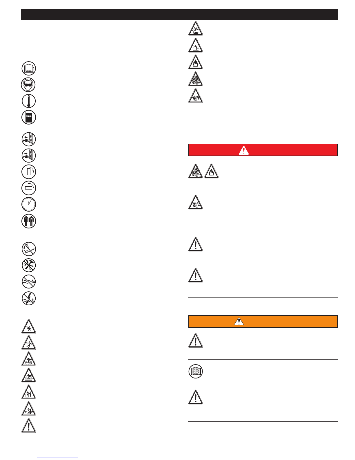
Safety Icon Nomenclature
Icons signal a type of hazard and warn of personal
protection issues, prohibited actions, and hazard
avoidance.
SAFETY
Slipping injury
Tripping injury
Personal Protection
Read the manual
Eye protection
High water temperature
Fill water tank before connecting to electrical
power
Disconnect power
Connect power
Close gas valve
Open gas valve
Wait fi ve minutes
5
Use two people when lifting heavy objects
Prohibited Actions
No open fl ame
Use proper tools
Do not use if submerged under water
No liquid around electrical component
Fire hazard
Explosion hazard
Provide proper ventilation
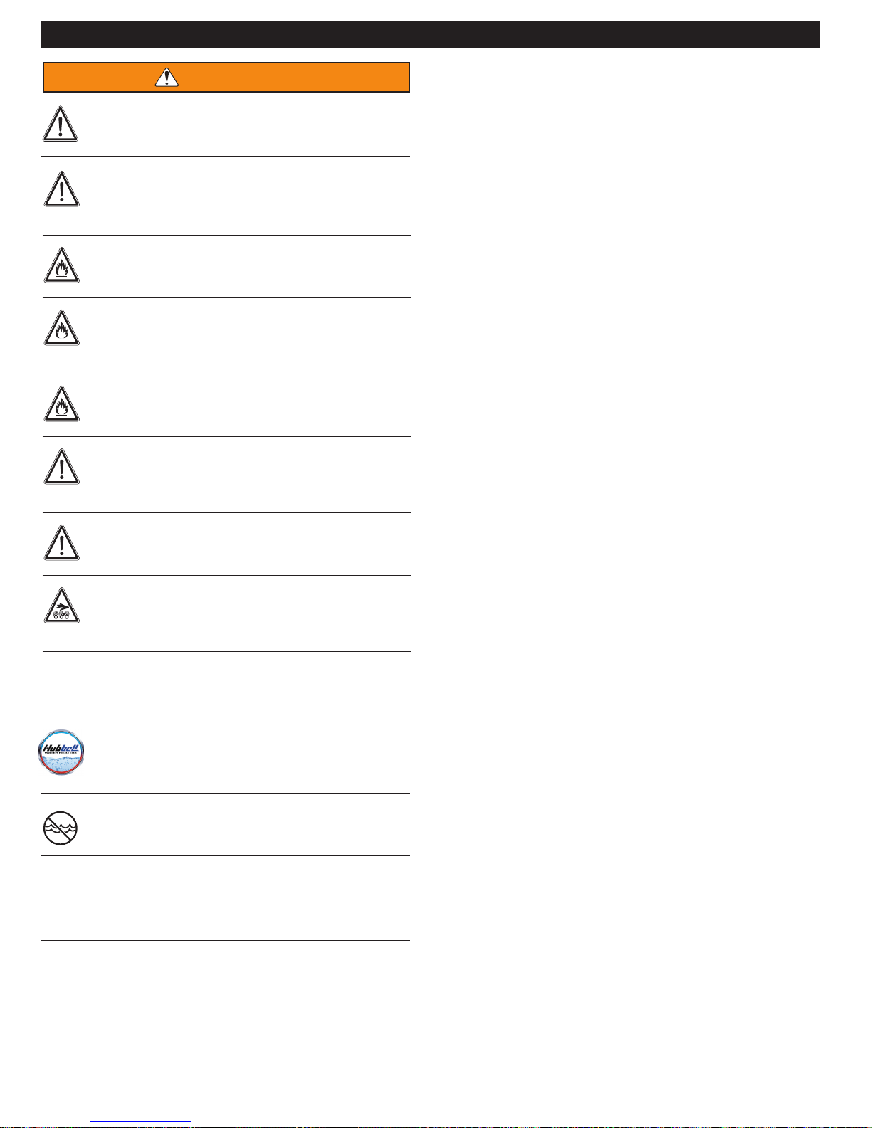
Operation and Installation Warnings
To avoid serious injury or death, read, understand and
follow all the precautions listed here.
DANGER
Vapors from flammable liquids will explode and can
cause a fire, resulting in personal injury or death. The
water heater has a burner that can come on at any
liquids around the water heater.
for safe operation. Inspect the exterior exhaust gas outlet port and
fresh air inlet port on a regular basis to ensure they are functioning
properly.
the exhaust gases with a fully functional and calibrated flue gas
analyzer.
time and ignite vapors. DO NOT use or store flammable
Improper venting can cause a build-up of carbon monoxide.
Breathing carbon monoxide can result in brain damage or
death. DO NOT operate the water heater unless it is properly
vented to the outside and has an adequate fresh air supply
A concentration of carbon monoxide as small as 0.04% (400
parts per million) in the air can be fatal. When making high
fire
low fire adjustments, CO levels must be monitored
or
using a flue
than 400 ppm is exceeded at any time during operation.
Adjusting the “low fire offset” or the “main flow restrictor” in
small increments can result in a significant increase in CO
concentration. To avoid serious injury or death, DO NOT
make any adjustments to the gas valve without monitoring
gas
analyzer
such that a CO level of no more
Hazard Avoidance
Disconnect power electrical hazard
Electrocution or shock hazard
Hot liquid, burn hazard
Hot surface
Lifting hazard
Pressurized liquid
Safety alert symbol
WARNING
The Hubbell water heater must be installed by a licensed plumber,
licensed gas fitter, and/or professional service technician. Improper
installation and/or operation can cause a potentially hazardous
situation, which, if not avoided, could result in serious injury or
death, and will void the warranty.
Proper care is your responsibility. Carefully read and
understand the Operation Information in this manual before
operating the Hubbell water heater.
Make sure you know the location of the gas shut-off valve
and how to operate it. Immediately close the gas shut-off
valve if the water heater is subjected to fire, overheating,
flood, physical damage, or any other damaging condition that
might affect the operation of the unit. Have the water heater checked
by a qualified technician before resuming operation.
6
WARNING
Do not power up the unit unless the gas and water supply
valves are fully opened. Make sure the fresh air intake port
and exhaust gas port are open and functional.
DO NOT attempt to install, service, or repair this water heater
yourself. There are no serviceable parts which can be
changed by the owner. Contact a qualified technician if your
water heater needs repair or maintenance. Ask your gas
supplier
restrict or block the flow in or out of the
is repaired by a qualified technician.
is being used by other persons.
for a list of qualified service providers.
Keep the area around the water heater clean and free of all
materials that can burn. DO NOT store or place gasoline, oils,
spray paint, or other flammable products near the water heater.
DO NOT use spray paint, hair spray, or any other flammable
spray near the water heater or near the exterior fresh air inlet
port. DO NOT place any items in or around the exterior
exhaust gas outlet port and/or fresh air inlet port that could
vent system.
DO NOT store or place newspapers, laundry, or other
combustible items near the water heater or the exterior
exhaust gas outlet and/or fresh air inlet port.
The owner should inspect the system monthly for damage,
water stains, signs of rust, corrosion, and exhaust vent and
air intake blockage. If inspection of the unit shows signs of
damage, the water heater should be shut off until the
DO NOT allow children to operate this unit. DO NOT use this
unit if it does not appear to be operating correctly.
A qualified technician should service and inspect the water
heater annually.
The water heater temperature is factory set to 120°F (49°C).
To avoid scalding, always check the temperature of the hot
water before bathing, showering, washing, etc. DO NOT
adjust the water temperature while the Hubbell water heater
SAFETY
problem
IMPORTANT
Do not use the water heater if any part has
been under water. Immediately call a qualified service
technician and have the unit inspected. Replace any
components that have been under water.
The Hubbell water heater is equipped with a three prong plug. It
should only be plugged directly into a properly grounded three
prong receptacle. DO NOT remove the ground prong from the plug.
DO NOT alter or modify the water heater or water heater controls.
This can be dangerous and will void the warranty.
7
SAFETY
Always read and follow all warnings on water heater safety
decals and in the manual. If the Installation and Operation manual
is missing, go to our website at: www.hubbellheaters.com or
contact Hubbell (203-378-2659) for a replacement.
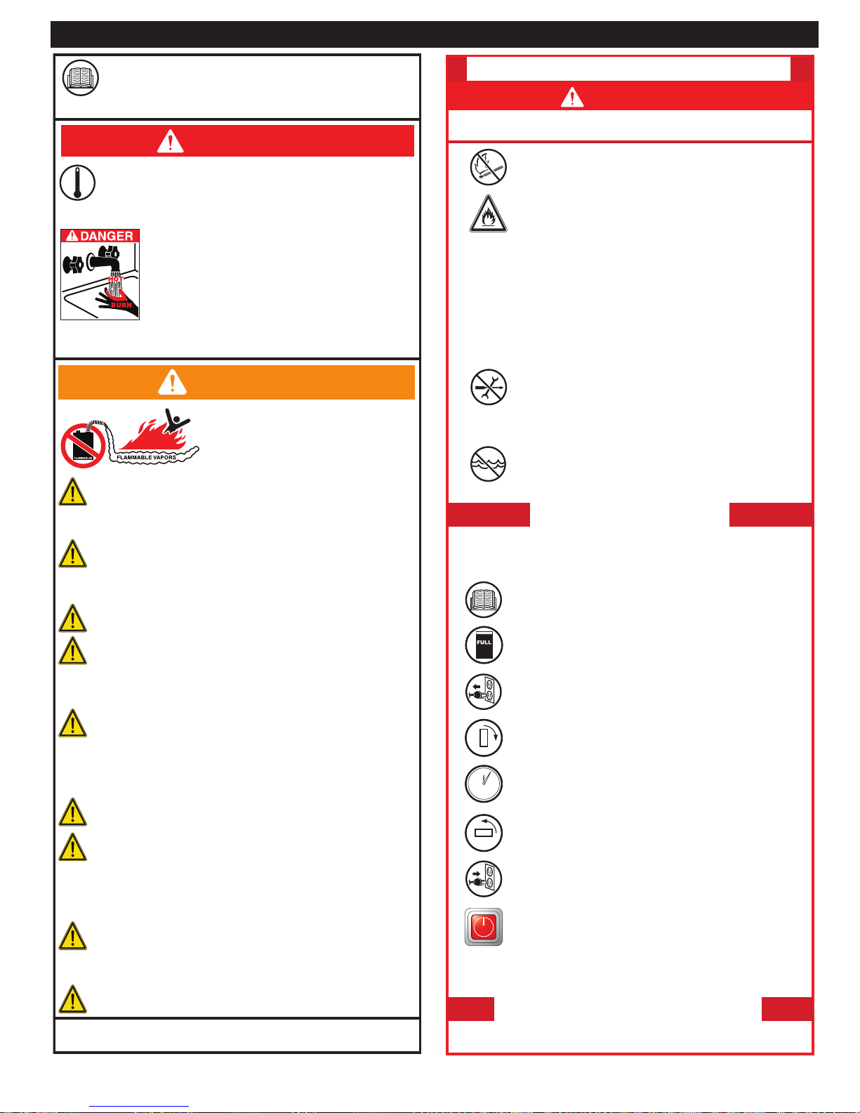
DANGER
Use this water heater at your own risk. The outlet
temperature of the Hubbell water heater is factory
preset to 120°F (49°C). The temperature can only be
changed by using the control panel on the front of the
water heater.
particular faucet, temperature limiting valves can be installed
by your service professional.
Hot water temperature over 125°F (52°C) can
cause severe burns instantly or death from
scalding. Children, disabled, and elderly are at
the highest risk of being scalded. Do not leave
children or the inf rm unsupervised. Check
temperature of hot water before taking a shower
or bath. To control water temperature to a
WARNING
Do not store or use gasoline or other
f ammable vapors and liquids in the
vicinity of this or any other appliance.
Flammable vapors can ignite and
cause serious damage or injury.
This water heater is factory preset for NATURAL GAS.
For propane conversion, refer to the manual.
Connecting the water heater to any other gas supply can result
in property damage, serious injury, and even death.
Suitable for water (potable) heating and
space heating. The water heater MUST NOT be
connected to any heating system or components previously
used with a nonpotable water heating appliance.
Do not use toxic chemicals, such as used for boiler
treatment, in potable water space heating systems.
This appliance must be installed in accordance with
local codes or, in the absence of local codes, the
National Fuel Gas Code, ANSI Z223.1/NFPA 54 or the
CSA B149.1, Natural Gas and Propane Installation Code.
A pressure relief valve complying with the Standard for
Relief Valves for Hot Water Supply Systems, ANSI Z21.22
or CAN1-4.4 Temperature, Pressure, Temperature and Pressure
Relief Valves and Vacuum Relief Valves must be installed in a
proper outlet port of water heater at the time of installation
according to local codes.
No valve is to be placed between the relief valve and the
water heater.
The discharge from the temperature/pressure relief valve
should be directed to the ground or into a drain system
which will prevent a burn hazard or property damage. The
piping must not have a reducing coupling or other restriction
in the discharge line. The discharge line must be installed to
allow complete drainage of both the valve and line.
If the system requires water for space heating at
temperatures higher than required for other uses, a
mixing valve must be installed to temper the water for those
other uses in order to reduce scald hazard potential.
The pressure relief valve must not be removed or
plugged.
Hubbell
www.hubbellheaters.com
Pressure Relief Valve
Phone: 203-378-2659
IGT-LBL-0002-01
FOR YOUR SAFETY READ BEFORE OPERATING
DANGER
If you do not follow these instructions exactly, a f re or explosion
may result, causing property damage, personal injury, or loss of life.
A. This water heater does not have a pilot. It is
equipped with an ignition device which automatically
lights the burner. Do not try to light burner manually.
B.
settle on the f oor.
C.
service technician. Force or attempted repair may result in a
f re or explosion.
D.
system and any gas control which has been under water.
If water heater is not operating, follow these instructions. This
appliance is equipped with an ignition device which automatically lights the burner. Do not try to light the burner manually.
1.
2.
3.
4.
5.
6.
7.
8.
If water heater will not operate, follow instructions “To Turn Off
Gas To Water Heater” and call your service technician or gas
supplier.
1. Turn OFF electrical power to water heater.
2. Turn manual gas shut-off valve to OFF position.
BEFORE OPERATING, smell all around the water
heater area for gas. Be sure to smell next to the
f oor because some gas is heavier than air and will
WHAT TO DO IF YOU SMELL GAS
• Do not try to light any appliance.
• Do not touch any electric switch; do not use any phone
in your building.
• Immediately call your gas supplier from a neighbor’s
phone. Follow the gas supplier’s instructions.
• If you cannot reach your gas supplier, call the f re or police
department.
Use only your hand to turn manual gas shut-off valve.
Never use tools. If manual gas shut-off valve will not
turn by hand, don’t try to repair it, call a qualif ed
Do not use this water heater if any part has been under
water. Immediately call a qualif ed service technician
to inspect water heater and replace any part of control
OPERATING INSTRUCTIONS
STOP! Read the safety information above on this
label.
Never use water heater unless it is completely f lled
with water.
Turn OFF electrical power supply to the water heater.
Turn gas shut-off valve clockwise to “OFF” position.
Do not force.
Wait f ve (5) minutes to clear out any gas. If you then
smell gas, STOP! Follow step “B” above on this
5
label. If you don’t smell gas, go to next step.
Turn manual gas shut-off valve to “ON” position.
Turn ON electrical power to unit.
Wait until default temperature (120°) is displayed.
Set desired water temperature. Turn on hot water
faucet.
TO TURN OFF GAS TO WATER HEATER
8
SAFETY
Toujours lire et suivre tous les avertissements sur les
décalcomanies de sécurité sur le chauffe-eau et dans le
manuel. Si le manuel d'installation et de fonctionnement
n'est pas disponible, visiter le www.hubbellheaters.com ou
contacter Hubbell (203) 378-2659 pour un remplacement.
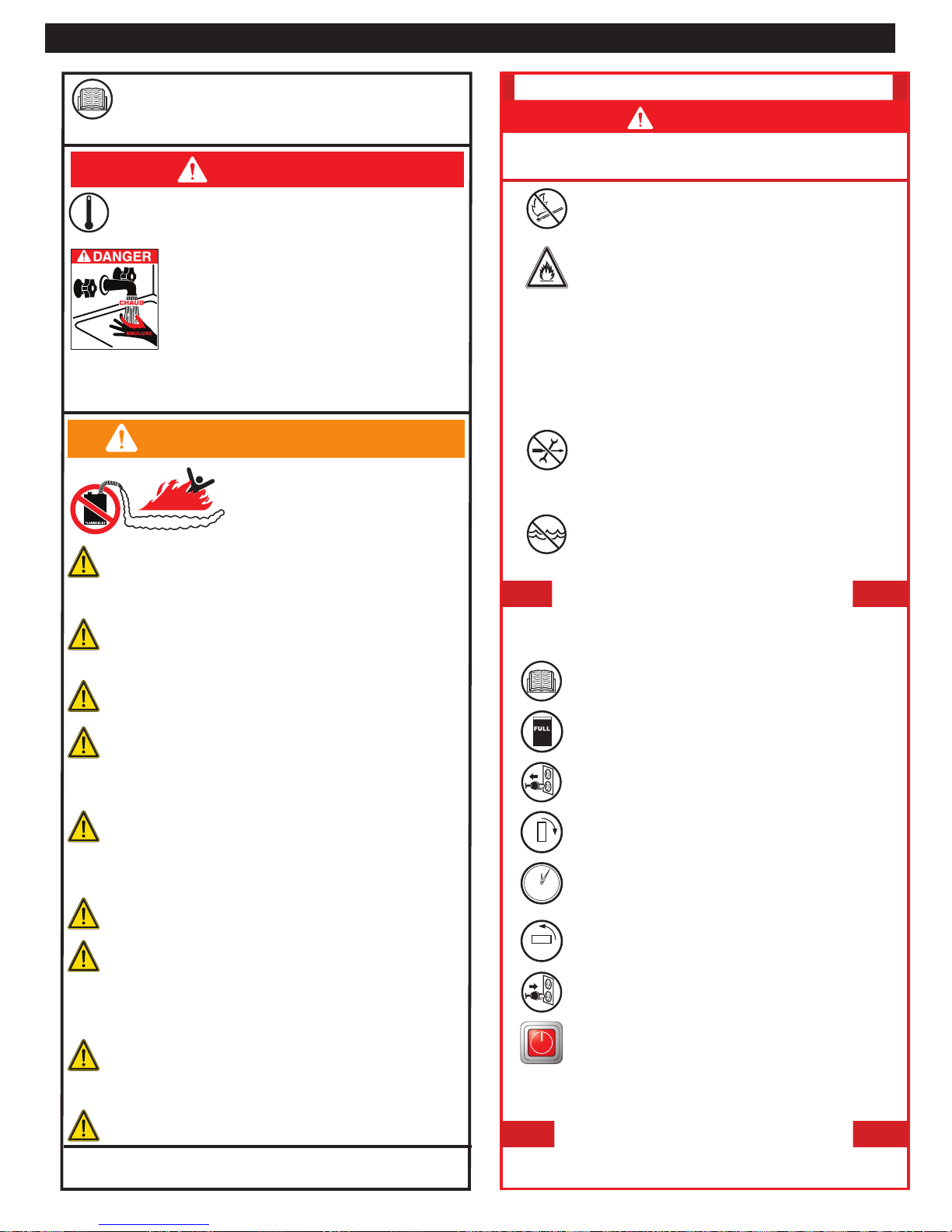
DANGER
Utiliser ce chauffe-eau à vos propres risques. La température
de sortie du chauffe-eau Hubbell est réglée en usine à 49 °C
(120 °F). La température peut être modifiée seulement en
utilisant le panneau de commande à l'avant du chauffe-eau.
Une température d'eau chaude de plus de 52 °C
(125 °F) peut causer des brûlures sévères instantanément ou la mort par ébouillantage. Les enfants,
les personnes handicapées et les personnes âgées
sont les plus à risque d'être ébouillantées. Ne pas
laisser les enfants ou les infirmes sans supervision.
Vérifier la température de l'eau chaude avant de
prendre une douche ou un bain. Des vannes régulatrices de
température peuvent être installées par votre professionnel
d'entretien afin de contrôler la température de l'eau sur un robinet en
particulier.
AVERTISSEMENT
Ne pas entreposer ou utiliser de gazoline
ou autres vapeurs ou liquides
inflammables à proximité de cet appareil
Vapeurs inflammables
Ce chauffe-eau est préréglé en usine pour le GAZ
NATUREL. Pour la conversion au propane, se référer au
manuel. Connecter le chauffe-au à toute autre alimentation
en gaz peut causer un dommage à la propriété, une blessure
sérieuse et même la mort.
Convient pour le chauffage de l'eau (potable) et le chauffage
des locaux. Le chauffe-eau NE DOIT PAS être connecté à un
système de chauffage ou à des composants utilisés pour un
appareil de chauffage d'eau non potable.
Ne pas utiliser de produits chimiques toxiques, comme
ceux utilisés pour le traitement de chaudière, dans des
systèmes de chauffage de locaux et d'eau potable.
Cet appareil doit être installé conformément aux codes
locaux, ou , en l'absence de codes locaux, selon le National
Fuel Gas Code, ANSI Z223.1/NFPA 54 ou le Code
d'installation du gaz naturel et du propane, CSA B149.1.
Une soupape de surpression conforme à la norme Relief
Valves for Hot Water Supply Systems, ANSI Z21.22 ou
CAN1-4.4 Temperature, Pressure, Temperature and
Pressure Relief Valves and Vacuum Relief Valves doit être
installée dans le bon port de sortie du chauffe-eau au moment de
l'installation conformément aux codes locaux.
Aucune vanne ne doit être placée entre la soupape de
surpression et le chauffe-eau.
La décharge de la soupape de température/surpression
devrait être dirigée vers le sol ou dans un système de drain
qui empêchera un risque de brûlure ou un dommage à la
propriété. La tuyauterie ne doit contenir aucun raccord réducteur
ou autre restriction dans la ligne de décharge. La ligne de
décharge doit être installée afin de permettre un drainage complet
de la vanne et de la ligne.
Si le système exige de l'eau pour le chauffage de locaux à
des températures plus élevées que celles pour d'autres
usages, une vanne de mélange doit être installée pour
tempérer l'eau pour ces autres usages afin de réduire la possibilité de blessure par ébouillantage.
La soupape de surpression ne doit pas être retirée ou
bouchée.
Hubbell
www.hubbellheaters.com
ou autre. Les vapeurs inflammables
peuvent s'enflammer et causer un
dommage sérieux ou une blessure.
Soupape de surpression
Téléphone: 203-378-2659
GT-LBL-0003-01
POUR VOTRE SÉCURITÉ, LIRE AVANT D'UTILISER
DANGER
Si vous ne suivez pas ces instructions exactement, un incendie ou
une explosion pourrait résulter causant des dommages à la
propriété, une blessure personnelle ou une perte de vie.
Ce chauffe-eau n'a pas de pilote. Il est muni d'un
A.
B.
Ne pas essayer d'allumer aucun appareil•
• Ne toucher aucun interrupteur électrique; n'utiliser aucun
•
•
C.
D.
Si le chauffe-eau ne fonctionne pas, suivre ces instructions. Cet
appareil est muni d'un dispositif d'allumage qui allume automatiquement le brûleur. Ne pas essayer d'allumer le brûleur manuellement.
1.
2.
3.
4.
5.
6.
7.
8.
Si le chauffe-eau ne fonctionne pas, suivre les instructions
« Pour arrêter l'alimentation en gaz au chauffe-eau » et appeler
votre technicien d'entretien ou votre fournisseur de gaz.
1. METTRE HORS FONCTION l'alimentation électrique au chauffe-eau.
2. Tourner la vanne d'arrêt manuelle du gaz à la position d'arrêt (OFF).
dispositif d'allumage qui allume automatiquement
le brûleur. Ne pas essayer d'allumer le brûleur
manuellement.
AVANT D'UTILISER, sentir tout autour du chauffe-eau
pour détecter une odeur de gaz. S'assurer de sentir
près du plancher parce que certains gaz sont plus
lourds que l'air et retombent sur le plancher.
QUE FAIRE SI VOUS SENTEZ DU GAZ
téléphone dans votre édifice.
Appeler immédiatement votre fournisseur de gaz à partir du
téléphone d'un voisin. Suivre les instructions du fournisseur de gaz.
Si vous ne pouvez pas rejoindre votre fournisseur de gaz, appeler
le service d'incendie ou de police.
Utiliser seulement votre main pour tourner la vanne
d'arrêt manuelle du gaz. Ne jamais utiliser d'outils. Si la
vanne d'arrêt manuelle du gaz ne peut pas être tournée
à la main, ne pas essayer de la réparer, appeler un
technicien d'entretien qualifié. Une réparation forcée ou tentée
pourrait causer un incendie ou une explosion.
Ne pas utiliser ce chauffe-eau si une partie de celui-ci a
été sous l'eau. Appeler immédiatement un technicien
d'entretien qualifié pour inspecter le chauffe-eau et
remplacer toute partie du système de commande et
toute commande de gaz qui a été sous l'eau.
INSTRUCTIONS DE FONCTIONNEMENT
ARRÊTEZ! Lire les renseignements de sécurité
ci-dessus sur cette étiquette.
Ne jamais utiliser le chauffe-eau à moins qu'il soit
entièrement rempli d'eau.
METTRE HORS FONCTION l'alimentation électrique au
chauffe-eau.
Tourner la vanne d'arrêt manuelle du gaz dans le sens
des aiguilles d'une montre à la position d'arrêt (OFF).
Ne pas forcer.
Attendre cinq (5) minutes pour laisser le gaz s'évaporer.
Si vous sentez du gaz, ARRÊTEZ! Suivre l'étape « B »
ci-dessus sur cette étiquette. Si vous ne sentez pas de
5
gaz, passer à l'étape suivante.
Tourner la vanne d'arrêt manuelle du gaz à la position
de fonctionnement (ON).
METTRE EN FONCTION l'alimentation électrique à
l'appareil
Attendre jusqu'à ce que la température
par défaut (120°) soit affichée. Régler la température
désirée pour l'eau. Ouvrir le robinet d'eau chaude.
POUR ARRÊTER L'ALIMENTATION
EN GAZ AU CHAUFFE-EAU
g
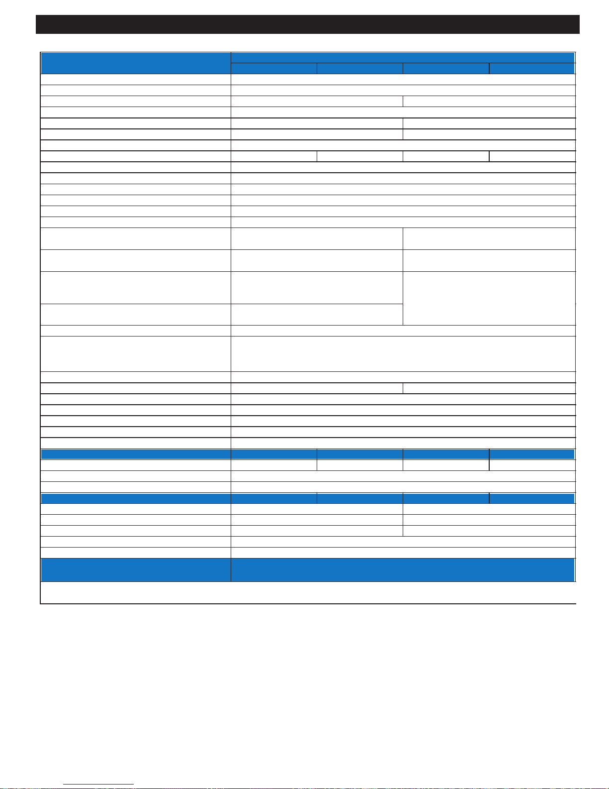
TECHNICAL SPECIFICATIONS
Parameters
Type
Fuel
GX200 GX200P GX250 GX250P
Indoor, Wall hung, Fully Condensing
Preset for NG / LP Convertible
Models
Minimum / Maximum Input (Btu/h)
Combustion Efficiency
98%
Thermal Efficiency
Energy Factor
Dimensions H x W x D (inches)
Water Inlet / Outlet Connection
Gas Inlet Connection
Minmum Flow Rate
Ignition
Venting Type
Venting Materials
Max 3” Vent Length - Single Pipe / Power Vent
Max 3” Vent Length - Two pipe / Direct Vent
Max 2” Vent Length - Single Pipe / Power Vent
(2” not allowed at elevations above 4,000 ft)
Max 2” Vent Length - Two Pipe / Direct Vent (2”
not allowed at elevations above 4,000 ft)
Common Venting
No minimum flow rate for "P" models / 0.6 GPM
Direct Vent (2 pipe - intake & exhaust), Power vent (1 pipe - exhaust only)
Sch. 40 PVC, Sch. 40 CPVC, Polypropylene, Stainless Steel
200 ft, deduct 5 ft per 90° elbow 130 ft, deduct 5 ft per 90° elbow
100 ft, deduct 5 ft per 90° elbow 65 ft, deduct 5 ft per 90° elbow
26 ft, deduct 5 ft per 90° elbow
21 ft, deduct 5 ft per 90° elbow
25.9 x 17.5 x 14.2 (3.7 cu. ft)
3/4" NPT
3/4" NPT
Electronic Spark Ignition
Yes
Flame Rod, Thermal Fuse, Overheat Prevention Device, Fan Speed Monitor, Flue
Safety
Temperature Monitor, Blocked Vent Detector, Water Leak Detector, Water Shut-Off
Valve, 2X10A Fuse, Dual Flame Sensing
Water Pressure Min / Max (PSI)
NG/LP- Minimum Static Gas Pressure 1/2"
NG/LP- Minimum Static Gas Pressure 3/4"
NG/LP - Maximum Static Gas Pressure
Gas Pressure for Adjustments
Electrical
Power Consumption
Features
5" (non-corrugated, black iron) 6" (non-corrugated, black iron)
2.5" (non-corrugated, black iron)
500W (Max 4.2 Amps), 8W (Standby)
GX200 GX200P GX250 GX250P
30 / 150
14”
8" for NG, 11" for LP
120V AC, 60 Hz
Recirculation / Tank Loading No-Pump Built-In Pump No-Pump Built-In Pump
Cascading
Heat Exchanger
Performance
Hot Water Capacity (35F Rise)
Hot Water Capacity (45F Rise)
Hot Water Capacity (77F Rise)
GX200 GX200P GX250 GX250P
10.8
8.4
5.0
Domestic Mode Temp. Settings
Commercial Mode Temp. Settings
Warranty (with recirculation)
Note: 1Due to Hubbell's Policy of continuous product improvements, design, and technical specifications are subject to change
2
Energy Star and Low NOx are applicable to GX200 and GX200P models.
Residential - Heat Exchan
Commercial - Heat Exchanger coil – 6 years, Parts – 5 years, Labor – 1 year
Masterless, 10 units
Expandable, Stainless 316L
100 – 140°F
100 – 185°F
er coil - 15 years, Parts – 5 years, Labor – 1 year
000,052/000,03059,991/000,03
%29%49
A/N39.0
89098909)sbl(thgieW
N/A
13.2
10.3
6.0
10
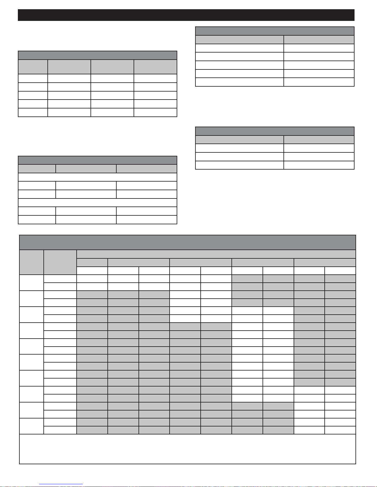
TECHNICAL SPECIFICATIONS
In order for the water heater to operate properly and
efficiently, the clearances specified in the table below are
required.
Required Mounting Clearances
Location From
Combustibles
Top 6” (15.2 cm) 2” (50.8 cm) 12” (30.4 cm)
2
Back
5/8” (15.8 mm) 5/8” (15.8 mm) 5/8” (15.8 mm)
Sides 1” (25.4 mm) 1/2” (12.7 mm) 5/8” (15.8 mm)
Front 2” (5.1 cm) 2” (5.1 cm) 30” (76.2 cm)
Bottom 12” (30.4 cm) 12” (30.4 cm) 12” (30.4 cm)
1
Service clearances are suggested dimensions to allow for normal
service of the unit.
2
Installing (hanging) the unit with the included brackets automatically
sets this dimension.
CO2 and CO Standards
Description CO2 Range (%) Max. CO Level (ppm)
High Fire 8.8% to 9.1% < 200 ppm
Low Fire 8.6% to 8.9% < 60 ppm
High Fire 8.8% to 9.1% < 200 ppm
Low Fire 8.6% to 8.9% < 60 ppm
From Non-
Combustibles
Natural Gas
LP Gas
Service
Clearance
1
Top Connections
Description Specification
2
Gas Supply Inlet Connection 3/4” Male NPT
Cold Water Inlet Connection
Hot Water Outlet Connection
3/4” Female NPT
3/4” Female NPT
Exhaust Gas Vent 3” O.D. PVC Schedule 40
Fresh Air Intake 3” O.D. PVC Schedule 40
1
Requires a 3” to 2” reducer when using 2” venting pipe.
2
Using sizes other than specified can cause damage to the water
heater and will void the warranty.
Bottom Connections
Description Specification
1
Drain Connection 3/4” Female NPT
Condensate Drain Connection 3/4” Nipple (3/4” flex hose)
Power Supply 120V AC Power Cord
1
Using sizes other than specified can cause damage to the water
heater and will void the warranty.
1
1
Max Vent Length For Various Duct Sizes And
Number Of Units
Duct Size and Model
Number
of Units
1
2
3
4
5
6
7
8
9
10
Venting
Type
2” 3” 4” 6” 8”
GX200
(P)
GX200
(P)
GX250(P) GX200(P) GX250(P) GX200(P)
GX250
(P)
GX200(P) GX250(P)
1 pipe - PV 26 200 130 200 130
2 pipe - DV 21 100 65 100 65
1 pipe - PV 200 130
2 pipe - DV 100 65
1 pipe - PV 100 30 200 130
2 pipe - DV 50 30 100 65
1 pipe - PV 200 130
2 pipe - DV 100 65
1 pipe - PV 200 130
2 pipe - DV 100 65
1 pipe - PV 200 130
2 pipe - DV 100 65
1 pipe - PV 150 45
2 pipe - DV 75 45
1 pipe - PV 100 30 200 130
2 pipe - DV 50 30 100 65
1 pipe - PV 200 130
2 pipe - DV 100 65
1 pipe - PV 200 130
2 pipe - DV 100 65
PV = Power Vent
DV = Direct Vent
Note: Reduce the maximum equivalent length above by 5 feet per 90° elbow used and by 2 feet per 45° elbow.
Do not exceed the above set limits.
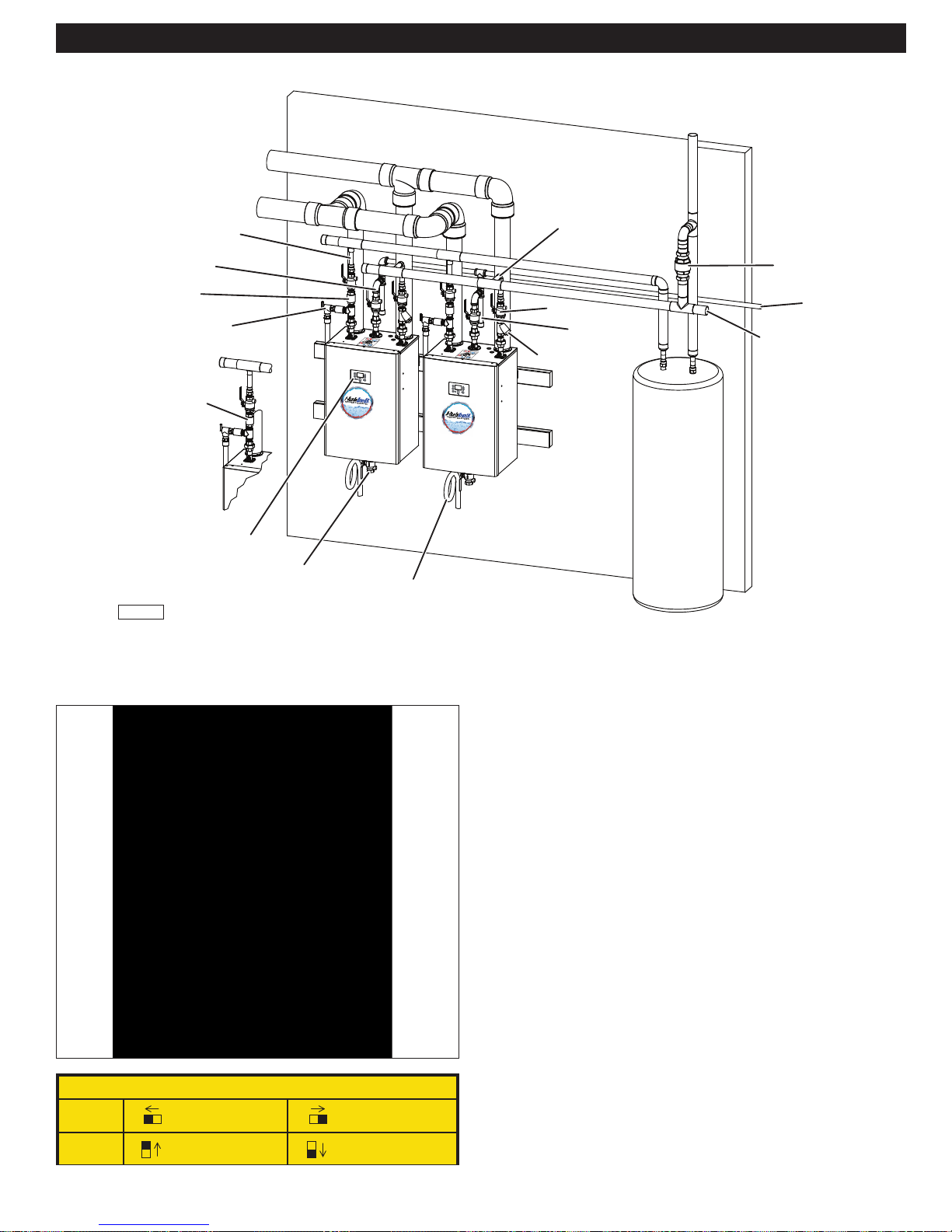
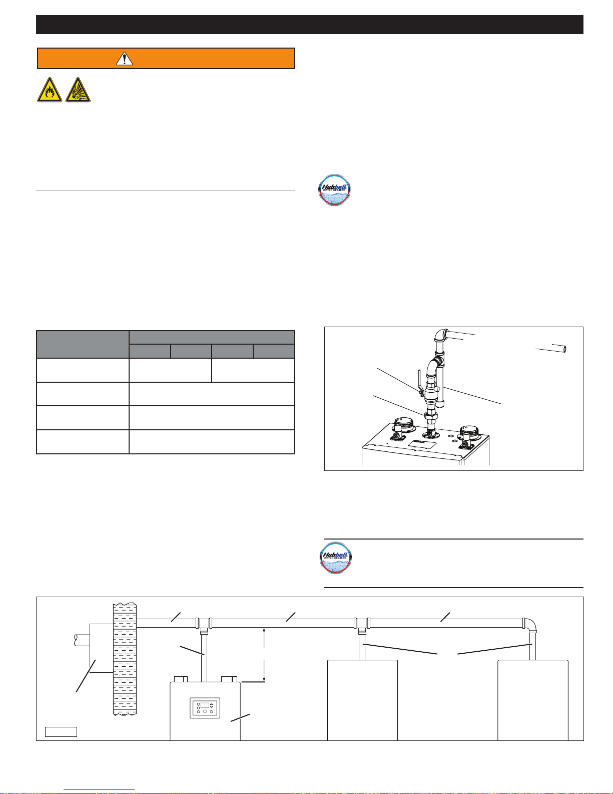
EXHAUST
HOT WATER
OUT
GAS LINE
CHECK
VALVE
TEMPERATURE
AND PRESSURE
VALVE
CHECK
VALVE
INLET
SPECIFICATIONS (NOMENCLATURE)
HOT WATER
TO USAGE
COLD WATER
INLET
GATE VALVE
GAS LINE
WATER TRAP
STRAINER
HOT
WATER
STORAGE
TANK
POINT
CHECK
VALVE
GAS
LINE
COLD WATER
IN
CONTROL
PANEL
WATER HEATER
DRAIN VALVE
IH-01
CONDENSATE
DRAIN
Typical installation of GX200P piped with storage tank.
DIP Switch Locations on Control Board
DIP Switch Settings (Réglages des commutateurs DIP)
SW1
SW2
Propane
Cascade Termination ON
(Terminaison en cascade ON)
Natural Gas
(Gaz naturel)
Cascade Termination OFF
(Terminaison en cascade OFF)
12
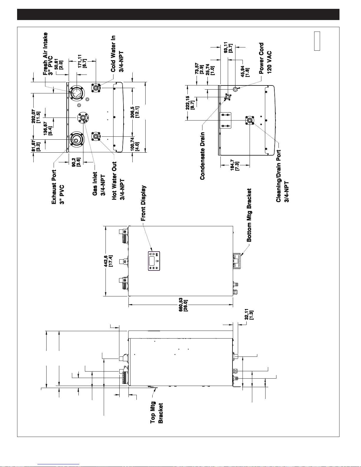
DIMENSIONAL SPECIFICATIONS
Selecting a Location
IH-79
68,86
[2 3/4”]
155,4
[6 1/8”]
35,36
[1 3/8”]
442,6
[17 7/16”]
Top View
Left
Side
Side
Right
Bottom View
361 ,3
[14 1/4”]
Mounting
Wall Surface
347,3
[13 11/16”]
Exhaust Port
14
[9/16”]
3” PVC
64,6
[2 9/16”]
Hot Water
3/4 NPT
Gas Inlet
102,4
[4 1/8”]
Out
3/4 NPT
185,1
[7 5/16”]
59,11
[2 5/16”]
57,79
[2 1/4”]
13
198,7
[7 25/32”]
Drain Port/PRV
107,1
[4 7/32”]
Front View
3/4-NPT
Power Cord
Condensate Drain
59,94
[2 3/8”]
L/H Side View

QUICK REFERENCE INSTALLATION GUIDE
The quick reference illustrations show the installation
of two GX200P water heaters connected together
with a storage tank. Installation of a single unit or
up to five units is basically the same. When
installing multiple units, refer to the Multiple Units
section for additional information.
1. Select a location. Note that the piping can be
confi gured to enter or exit the unit from either the left or
right side, as viewed from the front.
2. Mount the water heater(s) to the wall.
a.
Attach two 2x4 mounting blocks (at least 23” for a
single unit or 46” long for two units) to the wall. The
uppermost mounting boards should be at the
desired height for the top of the unit.
IH-80
e. Hang the unit on the mounting bracket. If multiple
units are installed, the spacing between the units
should be approximately 6”.
IH-81
3. Install the gas lines, as shown in the illustration.
b.
Attach a second mounting block 14” (center to
center) below the upper mounting block.
c. Attach metal mounting bracket(s) to the upper
mounting block approximately 3” on either side
of the center and 1/2” down from the top of the
mounting block.
d.
Adjust and tigthen the bottom bracket to the units so
that the unit to hangs vertically on the wall.
IH-82
a. Temporarily place a short section of 3” schedule
40 PVC pipe on one of the air inlets in order to
judge clearance allowances as the gas piping is
assembled.
b. Due to limited wall clearance, connect the union as
your fi nal step of gas piping.
c. Check for gas leaks at this point in the assembly
process.
14
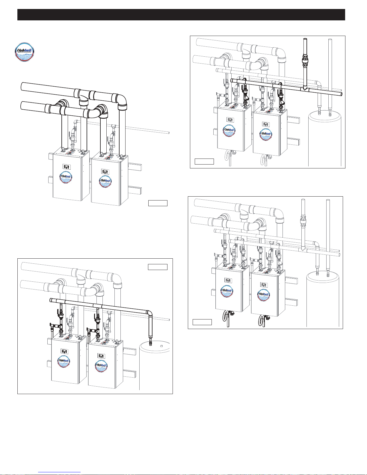
QUICK REFERENCE INSTALLATION GUIDE
Water Connections
4. Install the combustion air inlet and fl ue gas outlet PVC
piping.
Note: The inlet and outlet pipes from the unit are
3” diameter while the header piping is 4” diameter,
as shown in the illustration. The larger header
piping is required whenever multiple units are
installed.
4"
4"
3"
3"
3"
3"
6. Install and connect the cold water lines.
IH-85
7. Connect and route the condensate trap and drain line
to an appropriate discharge site or drain.
IH-83
5. Install and connect the hot water lines. If an optional
hot water storage tank is required, connect the hot
water lines to this tank. If required, install a pressure
relief valve or a temperature and pressure relief valve.
IH-84
IH-85a
8. Verify gas pressure.
9. Connect the 120 Volt power supply.
10. Test fi re the unit by opening all hot water faucets.
15

Gas Connection
PREPARATION BEFORE INSTALLATION
Selecting an Installation Site
IMPORTANT
When installing this water heater, follow all local
building codes and the current edition of the National
Fuel Gas Code (ANSI Z223.1/NFPA 54) in the USA or
National Gas and Propane Installation Code (CAN/CGA
B149.1) in Canada, when installing this product.
1. Select an interior location for the installation. Each
installation is unique; therefore, take the time to fi nd the
best location for the water heater.
a. Install the water heater near locations that use hot
water, such as bathroom, kitchen, or laundry room
faucets.
b. Select a location that minimizes the length of the
water pipe.
c. If the distances are long or if the faucet or appliance
requires “instant” hot water, we recommend running
a recirculation line back to the water heater from the
furthest fi xture. Insulate the hot water supply and
recirculation lines.
d. Select a location away from foot traffi c and away
from areas where dust, debris, chemical agents, or
other combustible materials could accumulate.
e. Allow suffi cient space for service and maintenance
access to all gas, water, and drain connections.
f. Make sure the location meets all building code
requirements.
IMPORTANT
Reduce the maximum equivalent length by 5 feet
per 90° elbow and by 2 feet per 45° elbow. Intake
and exhaust venting pipes have the same allowable
lengths. Do not exceed these set limits.
EXAMPLE: A 3” vent line or fresh air intake line
(Model GX200) with the six 90 degree elbows
would be limited to a length of 70 feet in a twin
pipe configuration
3. Locate the unit close to a drain and near gas and water
connections.
The water heater produces a signifi cant amount of
condensate during normal operation and should be
located near a suitable drain where damage from
a possible leak will be minimal. Installing the water
heater in a location without a drain will void the
warranty and Hubbell will not be responsible for
any resulting water damages that may occur as a
result. For additional information, refer to the Install
Condensate Drain section.
The water heater should be located in an area where
leakage from the unit or water pipes will not result in
damage to the area around the appliance or to lower
fl oors of the structure. When such locations cannot
be avoided, it is recommended that a suitable drain
pan, adequately drained, be installed under the water
heater. The pan must not restrict combustion air fl ow.
g. Make sure the wall surface the water heater is
mounted onto will support the weight of the unit.
SAFETY
INSTRUCTIONS
The Hubbell .. 200 and GX250 water heaters weigh 90 lbs. The
GX200P and GX250P weigh 98 lbs.
2. Minimize the distance that the exhaust gas vent and
fresh air intake must travel to an exterior wall.
a. The exhaust vent outlet must not be located next to
a walkway, near soffi t vents, crawl space vents, or
other areas where condensate (water vapor) could
cause damage or create a hazard.
b. The fresh air inlet vent must be located at least 12”
from the exhaust vent.
c.
Contaminated or dirty air drawn into the intake
pipe can damage the water heater. The Hubbell
warranty does not cover damage caused by
airborne contaminants.
16
PREPARATION BEFORE INSTALLATION
4. Locate the water heater and all water pipes in an area
where the ambient temperature always remains above
freezing.
NOTICE
In cold climates, if there is a power failure, the unit’s
freeze protection system will not operate, and can
result in water freezing inside the heat exchanger.
To prevent damage to the water heater, turn OFF the gas
supply and inlet
completely drain the unit.
Damage caused by freezing water is not covered by the
Hubbell warranty.
a. When the water heater is connected to an electrical
power supply, it will automatically prevent the water
inside the unit from freezing.
b. The unit’s freeze protection system will not prevent
the water in surrounding pipes from freezing.
water valve. Open the drain valve and
5. Select an appropriate location for the combustion air
and exhaust pipes to exit the house. Use the diagram
and chart on the next page to make this determination.
High Elevation Installations
For operation at elevations above 2,000 feet, Hubbell
model ratings should be reduced by 4% for each 1,000
feet above sea level.
Water Quality
Potable water is defined as drinkable water supplied from
utility or well water in compliance with EPA secondary
maximum contaminant levels (40 CFR part 143.3) as
shown in the table below. If your water contains
contaminants higher than outlined by EPA, then water
treatment is recommended and additional maintainence
may be required. If you suspect that your water is
contaminated in any way or water heater errors occur,
discontinue use of the water heater and contact an
authorized technician or licensed professional.
Contaminant Maximum Allowable Level
Total Hardness 200 mg/l (12 grains/gallon)
Aluminum 0.05 to 0.2 mg/l
Chloride 250 mg/l
Copper 1.0 mg/l
Iron 0.3 mg/l
Manganese 0.05 mg/l
pH 6.5-8.5
Sulfate 205 mg/l
Total Dissolved Solids (TDS) 500 mg/l
Zinc 205 mg/l
17
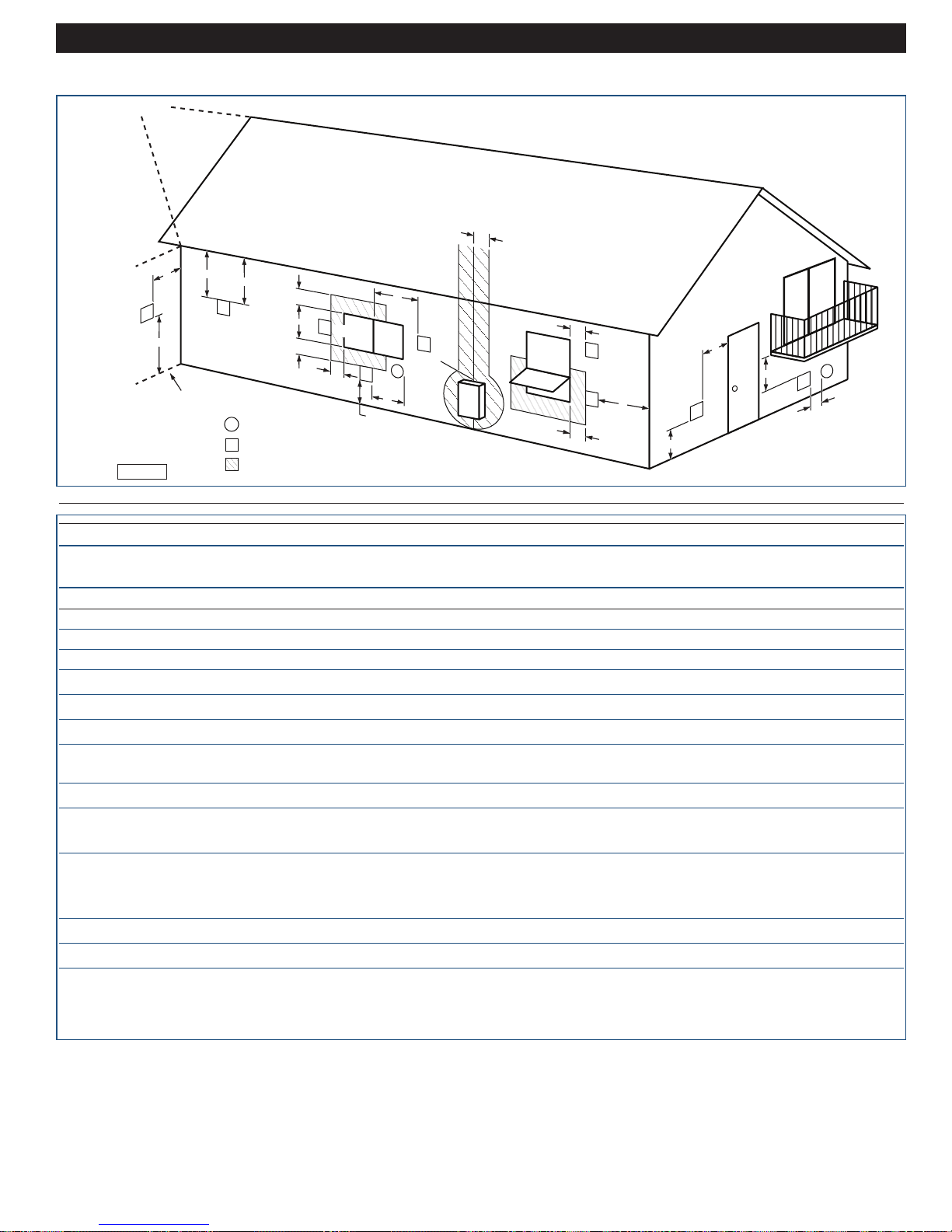
Venting Connections
D
IH-31
V
G
A
Inside Corner
Detail
E
V
Air Inside Inlet
X
V
Vent Terminal
Area Where Terminal is Not Permitted
PREPARATION BEFORE INSTALLATION
H
V
A
Fixed
Closed
J
B
V
I
X
Operable
Fixed
Closed
C
V
V
F
B
L
B
V
Operable
B
B
B
M
V
X
V
K
ANSI Z223.1 / NFPA 54 for USA and CAN/CSA B149.1 for Canada - Venting Requirements
USA Clearance Canada Clearance
Item Description Specification Specification
A Above grade, veranda, porch, deck, or balcony 1 ft 1 ft
B Window or door that may be opened 1 ft** 3 ft
C Permanently closed window * *
D Vertical clearance to a ventilated soffit, eves, or overhang 3 ft*** *
E Unventilated soffit, eves, or overhang 3 ft*** *
F Outside corner * *
G Inside corner * *
H Each side of centerline extended from meter/regulator * 3 ft within a height 15 ft above the
meter/regulator assembly
I Service regulator vent outlet * 3 ft
J Non mechanical air supply inlet or combustion air inlet
to any other appliance 1 ft** 3 ft
K Mechanical air supply inlet 3 ft above if 6 ft
within 10 ft
horizontally
L Above paved sidewalk or paved driveway on public property * 7 ft
M Under veranda, porch, deck, or balcony * 1 ft
*
Not specified in ANSI Z223.1 / NFPA 54 or CAN/CGA-B146.
Use clearances in accordance with local building codes and local gas supplier.
**
4 feet (1.2 m) below or to the side of opening and 1 foot (300 mm) above opening.
*** Hubbell recommendation.
18
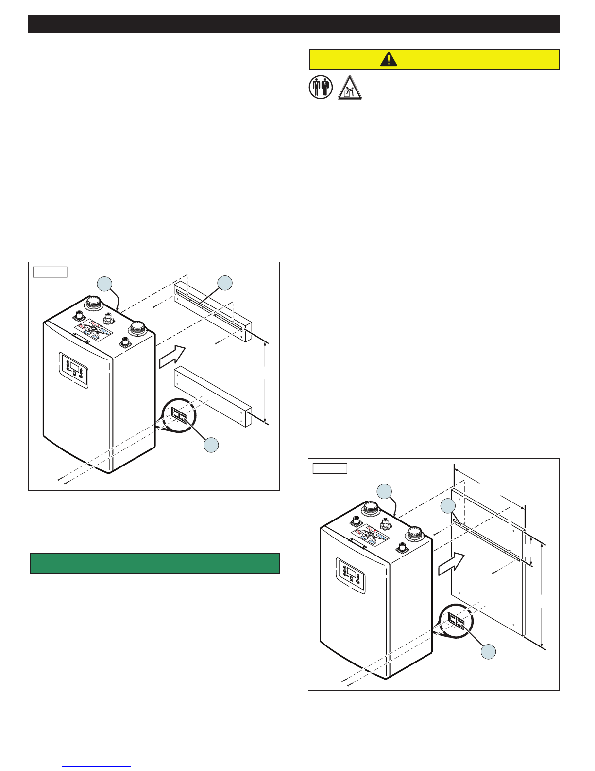
WALL MOUNTING
Secure the unit to the wall using either two wood
mounting blocks or one piece of 3/4” plywood, as
described in this section.
Mounting Block Installation Method
1. Attach two 2x4 or 2x6 mounting blocks (horizontal
framing), at least 18 inches long, to the wall.
a. In wood or steel construction, use adequate wood/
metal screws and secure the mounting blocks with
at least two screws in each vertical wall stud (four
screws total).
b. In concrete block or solid concrete wall construction,
attach the mounting blocks with at least four
masonry screws or suitable masonry wall anchors in
each mounting block.
IH-26
1
2
CAUTION
Lifting Hazard
According to the National Institute for Occupational
Safety and Health, the recommended maximum safe
lifting weight is 51 pounds, with all lifting conditions perfect—
minimal forward reach, steady load close to the body, straight back,
load between knees and shoulders, and good grips. To avoid
personal injury, always use these proper lifting techniques and use
two people to move the water heater which weighs 80 pounds.
3. With assistance, hang the unit on the upper wall
bracket, interlocking bracket (1) on the back of the unit
and wall bracket (2).
4. Install two appropriately sized wood screws in lower
bracket (3) to secure the unit to the wall.
5. Make sure the unit is plumb and level and tighten the
four sheet metal screws on bottom bracket (3). When
properly installed, there should be a 5/8” air space
between the back of the water heater and the mounting
blocks.
21”
3
2. Level upper bracket (2) and attach it to the mounting
block with at least four appropriately sized wood
screws (do not use drywall screws).
SAFETY
INSTRUCTIONS
The Hubbell water heaters weigh 90 to 100 lbs (40.8 to 45.4 kg) and
must be securely attached to the wall. Mounting hardware is
included and should be used to mount the unit.
Plywood Installation Method
1. Mount a piece of 3/4” plywood (at least 32” high x 20”
wide) to the wall.
a. In wood or steel construction, use adequate wood/
metal screws and secure the plywood with at least
two screws in each vertical wall stud.
b. In concrete block or solid concrete wall construction,
attach the plywood with at least four masonry
screws or suitable masonry wall anchors.
IH-27
1
20”
2
8”
32”
3
2. Follow Steps 2 through 5 in the above procedure to
complete the installation.
19
GAS CONNECTION
WARNING
FIRE AND/OR EXPLOSION HAZARD
To avoid serious injury or even death, the gas line
installation and the gas line inlet pressure test
must be done by a licensed professional.
Always match the water heater with the type of gas supplied to the
unit (natural gas or LP gas). The water heater is factory preset for
natural gas.
Make sure the gas line pressures are within normal limits. Pressures
outside normal limits can result in poor performance and hazardous
operating conditions.
1.
Determine if the Hubbell water heater will use natural
gas (factory preset) or LP (propane) gas.
a. To convert the unit to propane, refer to the Propane
(LPG) Conversion section in this manual.
b. Make sure your gas supply matches the rating decal
located on the side of the water heater.
2. Make sure the gas pressure meets the requirements
for the unit, as shown in the tables.
b. Measure the length of the gas supply line from the
gas meter to the water heater or other appliances
requiring gas.
c. Use the Gas Pipe Sizing tables in this manual or
refer to the gas line manufacturers sizing information
to determine the correct diameter for the supply pipe.
d. The diameter of the gas lines, shown in the
illustration, will vary according to the specifi c
installation requirements.
NOTE: Always clean the inside of the gas line of
any dirt or debris before connecting the piping to
the unit.
4. Install a gas union connection with a short piece of 3/4”
NPT pipe.
5. Following local building codes, install a manual shut-off
valve.
6.
Connect the manual shut-off valve to the gas supply
line. Also install a dirt pocket drip leg off of the main
supply line, as shown.
Models
Parameters
NG/LP- Minimum Static
Gas Pressure (1/2")
NG/LP- Minimum Static
Gas Pressure (3/4")
NG/LP - Maximum
Static Gas Pressure
Gas Pressure for
Adjustments
3.
Make sure the supply line is correctly sized for the
GX200 GX00P GX250 GX250P
5” (non-corrugated,
black iron)
2.5” (non-corrugated, black iron)
8” for NG, 11” for LP
6” (non-corrugated,
black iron)
14”
maximum output of the water heater model being
installed. The Hubbell water heater should be the
f r st appliance to be connected to the gas supply line.
a. Determine the gas requirement of the water heater(s)
and other appliances requiring gas. The supply line
must be sized according to the COMBINED total
maximum BTUH draw for all the appliances as if they
were all operating at the same time.
1” 1” 1”
Manual
Main Supply Line
Shut-off
Valve
Union
Drip leg
7. Leak test the gas line piping before placing the unit
in operation. Only use approved leak detector liquid
solutions to check for leaks.
IMPORTANT
Do not fire (operate) the water heater until all
connections have been completed and the heat
exchanger is filled with water.
1/2”
Gas
Meter
IH-77
Typical installation when using 1/2” gas line.
Home
Wall
Less then 40’
Hubbell
1/2”
Laundry Stove
20
GAS PIPE SIZING TABLES
Gas Pipe Sizing
This information is for reference only. Refer to gas pipe manufacturer specifications for actual delivery capacity. The DOE
standard for Natural Gas is 1100 BTU/ft3. Contact the local gas supplier for actual BTU/ft3 rating.
1/2” Black Iron Sizing
The following table shows gas supply in cubic feet per hour (CFH) assuming a specific gravity of 0.6 for Natural Gas, 0.585
for propane, pressure drop of 4.6” WC, and 5.0” WC. Contact your gas supplier for BTU/ft3 ratings. Use 1000 BTU/ft3 for
estimates.
Length (Including fittings)
Gas Pipe Size 5 10 15 20 25 30 35 40
Natural Gas 1/2” 571 404 330 286 255 233 216 202
LP 1/2” 578 409 334 289 259 236 219 204
Natural Gas Pipe Sizing
Maximum Natural Gas Delivery Capacity — Length of Black Iron Pipe in Feet
Pipe Cubic Feet per Hour (0.60 Specific gravity, 0.5 WC Pressure Drop)
Size 10 20 30 40 50 60 70 80 90 100 150 200
3/4” 363 249 200 171 152 138 127 118 111 104 84 72
1” 684 470 377 323 286 259 239 222 208 197 158 135
1-1/4” 1404 965 775 663 588 532 490 456 428 404 324 278
1-1/2” 2103 1445 1161 993 880 798 734 683 641 605 486 416
2” 4050 2784 2235 1913 1696 1536 1413 1315 1234 1165 936 801
Maximum Natural Gas Delivery Capacity — Length of Corrugated Stainless Steel Pipe in Feet
Pipe Cubic Feet per Hour (0.60 Specific gravity, 0.5 WC Pressure Drop)
Size 10 20 30 40 50 60 70 80 90 100 150 200
3/4” 206 147 121 105 94 86 80 75 71 67 55 48
1” 383 269 218 188 168 153 141 132 125 118 94 82
1-1/4” 614 418 334 284 251 227 209 194 181 171 137 116
1-1/2” 1261 888 723 625 559 509 471 440 415 393 320 277
2” 2934 2078 1698 1472 1317 1203 1114 1042 983 933 762 661
LP Gas Pipe Sizing
Maximum LP Gas Delivery Capacity — Length of Black Iron Pipe in Feet
Pipe Thousands of BTU/Hour, 0.5 WC Pressure Drop
Size 10 20 30 40 50 60 70 80 90 100 125 150 200
3/4” 567 393 315 267 237 217 196 185 173 162 146 132 112
1” 1071 732 377 323 286 259 239 222 208 197 174 252 213
1-1/4” 2205 1496 775 663 588 532 490 456 428 404 358 511 440
1-1/2” 3307 2299 1161 993 880 798 734 683 641 605 536 787 675
2” 6221 4331 2235 1913 1696 1536 1413 1315 1234 1165 1033 1496 1260
Maximum LP Gas Delivery Capacity — Length of Corrugated Stainless Steel Pipe in Feet
Pipe Thousands of BTU/Hour, 0.5 WC Pressure Drop
Size 10 20 30 40 50 60 70 80 90 100 150 200
3/4” 325 232 191 166 149 136 126 118 112 106 87 76
1” 605 425 344 297 265 241 222 208 197 186 143 129
1-1/4” 971 661 528 449 397 359 330 307 286 270 217 183
1-1/2” 1993 1404 1143 988 884 805 745 696 665 621 506 438
2” 4638 3285 2684 2327 2082 1902 1761 1647 1554 1475 1205 1045
21
 Loading...