

Page 1

INSTALLATION, OPERATION &
MAINTENANCE DATA SHEET
GO113 N34, GO114 N34, GOL113 & GO1114
ROTARY OPERATORS FOR POTENTIOMETERS,
FOR CLASS I, GROUPS B, C & D, CLASS II, GROUPS E, F &
G AND CLASS III HAZARDOUS LOCATIONS AND TYPE 3, 4
& 4X ENCLOSURES
GO113 N34, GO114 N34, GOL113 & GO1114
ROTARY OPERATORS FOR
POTENTIOMETER
CAUTION:
Before installing, make sure you are compliant with area classications, failure to do so may result in bodily injury,
death and property damage. Do not attempt installation until you are familiar with the following procedures. All
installation must comply with the applicable Electrical Code.
Make sure that the circuit is de-energized before starting installation or maintenance.
Verify that the installation is grounded. Failure to ground will create electrical shock hazards, which can cause
serious injury and or death.
Technical information, advice and recommendations contained in these documents is based upon information
that Killark believes to be reliable. All the information and advice contained in these documents is intended for
use only by persons having been trained and possessing the requisite skill and know-how and to be used by
such persons only at their own discretion and risk. The nature of these instructions is informative only and does
not cover all of the details, variations or combinations in which this equipment may be used, its storage, delivery,
installation, check out, safe operation and maintenance. Since conditions of use of the product are outside of the
care, custody and control of Killark, the purchaser should determine the suitability of the product for his intended
use, and assumes all risk and liability whatsoever in connection therewith.
3940 Dr. Martin Luther King Drive
St. Louis, MO 63113
P/N 00911740 FORM NO. K1081 R11/08 ECO-3-045-08
Page 1 of 3
Page 2

These operators will accept standard rotary
electrical devices with 1/4” diameter shafts,
such as potentiometers, and are designed
for enclosures that meet the requirements of
Article 500 of the National Electrical Code.
GO 113 N34 & GO 114 N34 devices are
designed for mounting in enclosures with
walls up to 1-1/2” thick. GOL113 & GOL114
devices are designed for mounting in
enclosures with walls up to 2-1/2” thick.
1. DIRECTIONS FOR INSTALLATION
WARNING: Be sure to turn OFF the supplying circuit
before beginning installation.
1. Using the installation drawings below as a
guide, drill and tap a ¾ -14NPSM-2B hole in the
enclosure cover / wall. The hole must be located
so that a at area is available to tighten the locknut
on the inside of the cover, and enough room is
allowed for mounting the dial assembly on the
outside. In addition, the inside cover surface must
be perpendicular to the threaded hole and smooth
in order to properly seat the sealing locknut. For
Group B locations, a minimum of 7 full threads
engagement is required and for Group C & D
locations, a minimum of 5 full threads is required.
For proper electrical clearance, these devices
should be mounted on 2-1/2” centers and 1-3/4”
from any vertical wall.
2. Remove the knob and dial and thread the
remainder of the assembly through the hole from
the inside of the cover until the end of the threaded
body is ush with the cover face.
3. Orient the assembly as desired, and tighten the
sealing locknut to secure it. (The assembly may be
staked in place, if desired).
4. (For GO113 N34 & GOL113) Position the dial plate
at the end of the body, drill the dial plate in the
enclosure cover / wall with a #47 drill, 3/1 6” to 1/4”
deep, and fasten the dial plate with the #2-56 selflapping screws provided. Attach the control knob
and secure it with its setscrews (you will need a
5/64” Allen wrench).
(4A) (For GO114 N34 & GOL114) Refer to the
drilling template and an Allen wrench which are
included to complete this installation.
3940 Dr. Martin Luther King Drive
St. Louis, MO 63113
P/N 00911740 FORM NO. K1081 R11/08 ECO-3-045-08
Page 2 of 3
Page 3
5. When installing the potentiometer or device,
secure it to the ex coupling with the setscrews
provided.
6. Wire the system, secure the enclosure and turn
ON the circuit to test the system.
NOTE: All installations must comply with
applicable local and/or National Electrical Code.
2. OPERATIONAL DATA
The devices used on these operators are electrical
arcing devices. Therefore, the enclosure in which
they are installed must be provided with external
seals, as required by NEC Articles 501-5 &
502-5. In addition, the enclosure must be marked
with a cautionary statement such as, “Caution:
Disconnect this device from the supplying circuit
before entering. Keep assembly tight while circuits
are alive.” This statement must be permanently
visible after the enclosure has been installed.
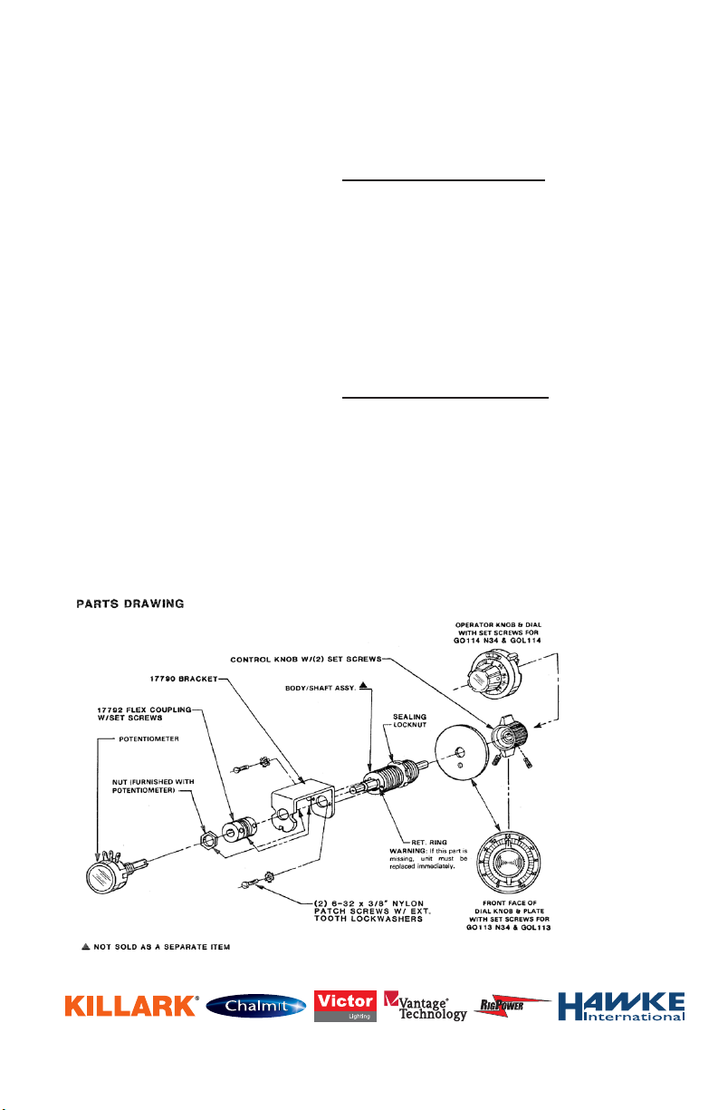
3. MAINTENANCE DATA
“GO” Series Rotary Operators should be periodically
checked for proper operation. The operator shaft
should be lubricated occasionally if operating
conditions require it.
WARNING: The surface between the body and shaft
is a ame path. If excessive play develops between
these parts, the body/shaft assembly must be
replaced at once. Refer to the Parts Drawing on left
and/or to the Killark factory for specic replacement
parts.
REMEMBER TO SAVE ONE OF THESE SHEETS FOR MAINTENANCE PERSONNEL
3940 Dr. Martin Luther King Drive
St. Louis, MO 63113
P/N 00911740 FORM NO. K1081 R11/08 ECO-3-045-08
Page 3 of 3
 Loading...