

Page 1

INSTALLATION, OPERATION &
MAINTENANCE DATA SHEET
G021 SINGLE PUSHBUTTON OPERATORS
FOR CLASS 1, GROUPS C & D, CLASS II, GROUPS E, F,
& G, & CLASS III HAZARDOUS LOCATIONS
G021 SINGLE PUSHBUTTON OPERATORS
CAUTION:
Before installing, make sure you are compliant with area classications, failure to do so may result in bodily injury,
death and property damage. Do not attempt installation until you are familiar with the following procedures. All
installation must comply with the applicable Electrical Code.
Make sure that the circuit is de-energized before starting installation or maintenance.
Verify that the installation is grounded. Failure to ground will create electrical shock hazards, which can cause
serious injury and or death.
Technical information, advice and recommendations contained in these documents is based upon information
that Killark believes to be reliable. All the information and advice contained in these documents is intended for
use only by persons having been trained and possessing the requisite skill and know-how and to be used by
such persons only at their own discretion and risk. The nature of these instructions is informative only and does
not cover all of the details, variations or combinations in which this equipment may be used, its storage, delivery,
installation, check out, safe operation and maintenance. Since conditions of use of the product are outside of the
care, custody and control of Killark, the purchaser should determine the suitability of the product for his intended
use, and assumes all risk and liability whatsoever in connection therewith.
3940 Dr. Martin Luther King Drive
St. Louis, MO 63113
P/N 00901223 FORM NO. K0330 R08/08 ECO-3-032-08
Page 1 of 3
Page 2

These G021 pushbutton operators are
designed for enclosures which meet the
requirements of Article 500 of the. National
Electrical Code, and are to be mounted in
enclosures with walls up to 1/2” thick.
INSTALLATION DRAWINGS
1. DIRECTIONS FOR INSTALLATION
Be sure to turn OFF the supplying circuit,
before beginning installation.
1. Using the installation drawings as a guide,
drill and tap a 3/4—14 NPSM—2B hole in the
enclosure cover.
2. The hole must be located so that a at area is
available to tighten the locknut on the inside
of the cover, and enough room is allowed
for mounting the nameplate on the outside.
In addition, the inside cover surface must be
perpendicular to the threaded hole .
3. For Group C & D locations, a minimum of 5 full
threads engagement is required. For proper
electrical clearance, these devices should be
mounted on 2-1/2” centers, and 1-3/4” from any
vertical wall.
4. Minimum electrical clearance between live parts
of opposite polarity is 3/16”; live parts to ground,
¼”.
5. Remove the cap and thread the remainder of
the assembly through the hole from the inside
until the threaded body protrudes approximately
1/4” on the face of the cover.
6. Orient the assembly as desired, and tighten
the locknut to secure it. (The assembly may be
staked in place, if desired).
7. Position the nameplate on the cover and install
the cap to hold it. Secure the cap with the set
screw.
8. Wire the system, secure the enclosure, and turn
ON the supplying circuit to test the system
3940 Dr. Martin Luther King Drive
St. Louis, MO 63113
P/N 00901223 FORM NO. K0330 R08/08 ECO-3-032-08
Page 2 of 3
Page 3
NOTE: All installations must comply with
applicable local and/or National Electrical
Code.
2. OPERATIONAL DATA
The contact blocks used on these operators are
electrical arcing devices. Therefore, the enclosure
in which they are installed must be provided
with external seals, as required by NEC articles,
501-2 & 502-5. In addition, the enclosure must
be marked with a cautionary statement such
as “Caution: Disconnect this device from the
supplying circuit before entering. Keep assembly
tight while circuits are alive.” This statement must
be permanently visible after the enclosure has
been installed.
3. MAINTENANCE DATA
“GO” Series Pushbutton Operators should be
periodically checked for damage and proper
operation.
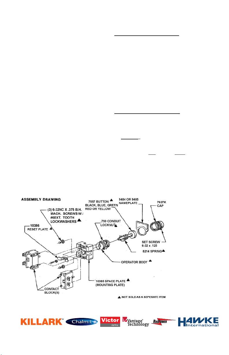
Warning: The surface between the operator body
and pushbutton shaft is a ame path. And part
numbers. If play develops between these parts,
both the shaft and the body must be replaced at
once. ▲ Refer to the Assembly Drawing and to
the Killark catalog for specic replacement parts
and part numbers.
REMEMBER TO SAVE ONE OF THESE SHEETS FOR MAINTENANCEs PERSONNEL.
3940 Dr. Martin Luther King Drive
St. Louis, MO 63113
P/N 00901223 FORM NO. K0330 R08/08 ECO-3-032-08
Page 3 of 3
 Loading...