

Page 1
SIZE 2, 3, 4, 5, 6, & 6A
SPECIFICATIONS
4220
Hubbell Industrial Controls, Inc.
EUCLID™ AC & DC POWER LIMIT SWITCHES
General Information
D-C Limit Switches are devices
that are used to interrupt the main
power circuit, setting up a dynamic
braking circuit that quickly stops
hook travel with a minimum of drift.
A-C Limit Switches are similar in
construction to D-C Limit Switches.
The difference is in operation. A-C
Limit Switches disconnect two
power lines to the hoist motor
which then is stopped by a magnetic brake.
♦ Positive trigger lock-out
♦ Direct action contact open-
ing and closing
♦ One-piece movable contacts
♦ Exclusive arc transfer action
♦ Sturdy housing
♦ Safety chain on cover
♦ Clearly marked leads
♦ Rugged construction
♦ Oversize ball bearings
November 2010
Repl. June 1994
Application
Euclid A-C and D-C Crane Power
Limit Switches provide dependable
protection against over-hoisting
problems such as damage to the
trolley frame and hoising mechanism. In case of over-travel, these
Limit Switches disconnect the hoist
motor from the line, preventing
further hoist motion.
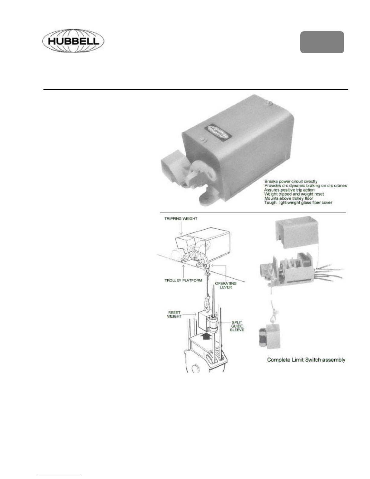
Operation
For dc operation the Power Limit
Switch is mounted on the trolley
floor of the crane. When the hook
block rises into the danger zone, it
lifts the suspended reset weight.
As the load of the reset weight is
removed from the operating lever,
the tripping weight (an integral part
of the operating lever) operates the
switch. Normally closed power
contacts are opened, normally
open dynamic braking contacts are
closed through a resistor. The
motor armature and series brake
are disconnected from the supply
line. The armature, series field and
braking resistor are connected in
series. RESULT: Setting of the
series holding brake and dynamic
breaking for a quick stop.
Reversing the crane controller lowers the hook to return the Limit
Switch to the “run” position by
means of the suspended reset
weight.
For ac operation, when the Power
Limit Switch is tripped, the shoe
brake is applied and the load is
stopped. The load cannot be
Hoisted when the Limit Switch is
tripped, but Lowering can be performed as usual because the lowering circuit is unaltered.
Page 2
Description
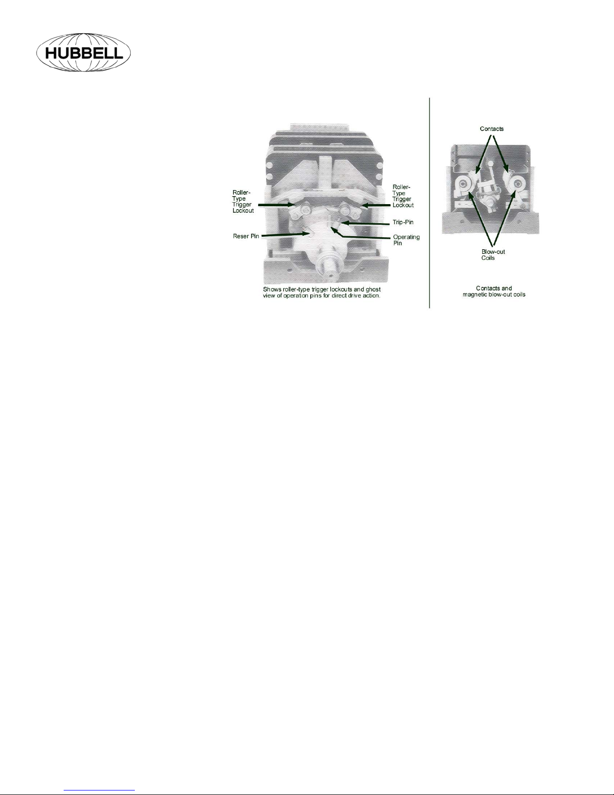
Positive trigger lock-out
Quick make-and-brake contacts, which
directly handle the motor circuit, are
locked in position until tripped. The
roller-type trigger lockouts prevent
positively any operation of the Limit
Switch until the full power of the hightensile, oil-tempered, magnafluxed
spring is available to assure extremely
fast operation for either tripping or resetting. Operation in any intermediate
position of the operating lever is impossible.
Direct contact opening and closing
In the remote possibility of spring failure, the contacts are operated by the
direct drive action of the tripping and
reset weights. In tripping, as the reset
weight causes the trip pin to engage
the operating pin to operate the contacts. In resetting, the reset-pin does
the job.
One piece movable contacts
The low inertia of these contacts practically eliminates any contact bounce.
Exclusive arc transfer system
This arc transfer system combined with
the shape of the arc chamber allows
greater arc interrupting in a smaller
space. The arc is confined to a controlled path for more efficient extinguishing. No destructive burning of the
contacts can occur as the arc is transferred to the rearmost part of the magnetic blowout coil guards and to the
central rod conductor in the arc shield.
A smaller Limit Switch is made possible.
Sturdy Housing
Size 4, 5, 6, & 6A cases are of cast
iron. Size 2 and 3 cases are molded
fiberglass. The cover is of tough glassreinforced polyester resin. It is easily
removed for ready access to the contacts.
Safety chain
The insulated cover is securely fastened to the case by means of a safety
chain to prevent loss when removed
from the case.
Clearly marked leads
Flexible leads for external connections
extend through snug-fitting neoprene
bushings in the back of the cast-iron
case. They are clearly marked to
speed installation.
Rugged Construction
High-quality materials reduce maintenance. All parts are of non-corrosive
materials. Contacts are hard-drawn
copper, except for sizes 3 & 6A which
use silver faced tips. The shaft is
stainless steel. All current-carrying
parts are copper or brass. Contact and
shunt fastening screws are stainless
steel.
Ball Bearings
Four oversize, double-sealed ball
bearings are permanently lubricated to
minimize friction and reduce maintenance.
Early Break Auxiliary (EBA)
The EBA option is available for crane
hoists that are controlled with AC or
DC drives. The EBA contacts (DPDT)
operate prior to the power contacts,
thus providing a signal to turn off the
drive before motor power interruption.
Installation
Euclid™ Type 4220 Crane Power Limit
Switches are easily field installed.
Mount horizontally on top of the trolley
frame of the hoist, with mounting feet
down. Install the split-sleeve suspended weight guide around the deedended cable. A bracket or striker plate
may be attached to the hook block, if
necessary, to lift the suspended weight
when hoising. Steel cable is furnished
for connection the suspended weight to
the operating lever.
D-C Units Only
The operating lever is adaptable for
either right or left-hand operation. Unless otherwise specified, right-hand
operation is furnished. Change in installation for left-hand operation can be
made either at the Factory or in the
field. Terminal markings only are affected. Refer to wiring diagram for
correct connections.
Resistors For D-C Limit Switches
Euclid™ Type K-exclusive continuous
wound, corrosion resistant, nonbreakable resistors, are specifically
designed for use with Euclid™ Type
4220 Hoist Limit Switches. See Price
List 4220.
Page 2
Page 3

SIZE A B
2 & 3 9-7/8 1-3/4 5-1/2 12-5/8 5-1/2 3-7/8 8-1/16 5-1/8 1-5/8 4-1/2 1/2 5-1/4 5 1-7/16 1-7/16 1-5/8 18 5 3-1/2 13/32 9/16 1/4
4 14-1/16 2-1/4 8-5/8 17-7/8 8-1/8 7-3/8 11-1/4 6-3/4 2-3/8 6-3/4 1-1/2 7-5/8
5 18-3/16 3 12-1/2 21-1/4 11 10-1/4 22-5/16 9-1/2 2-7/8 8-3/4 2-1/4 9-7/8 8-3/8 3
6 & 6a 24-13/16 7-1/2 18-1/4 27-3/4 16-7/8 15 22-5/16 14 3 11-1/2 2-3/4 13-1/2 7-1/4
NOTE: Catalog dimensions are not to be used for construction purposes. Prints will be furnished upon receipt of your order with your request for prints.
C
E
D
F G H J K L M N P R S T U V W X Y
6-
1-3/4 3 2-1/2 21 5-1/2 4 9/16 1/2 3/4
11/16
3-
3-3/4 27 7 5 9/16 5/16 1-1/8
11/16
2-
13/16
2-
3
27 9 6 13/16 7/16 1-1/2
13/16
APPROXIMATE WEIGHT IN POUNDS
PART NUMBER SIZE
4220-71220-001
4220-71221-001
4220-72530-001
4220-72531-001
4220-71240-001
4220-71241-001
4220-71250-001
4220-71251-001
4220-71260-001
4220-71261-001
4220-71260-003
4220-71261-003
2
3
4 70 98 100 128
5 170 210 225 265
6
6a
LIMIT SWITCH WITHOUT CABLE,
FITTINGS AND WEIGHT
LIMIT SWITCH WITH
CABLE, FITTINGS AND WEIGHT
NET BOXED NET BOXED
28 40 50 64
300 360 370 420
Page 3
Page 4

LIMIT SWITCH RESISTORS
FOR USE WITH DYNAMIC LOWERING CRANE HOISTS
250 VOLTS D.C.
DC LIMIT SWITCH RESISTORS
230/250 VDC, ENCLOSED Disc.
FOR USE WITH DYNAMIC LOWERING HOISTS Sch E37
HP
RANGE
5 – 10
11 – 13.5
14 – 26
27 – 33
34 – 45
46 – 65
66 – 100
101 – 135
136 – 200
201 – 265
PART
NUMBER
69453-069
69453-070
69453-071
69453-072
69453-073
69453-074
69453-075
69453-076
69453-077
69453-078
ABCDE
12.75”
15.50”
15.50”
15.50”
15.50”
15.50”
18.25”
21.00”
27.00”
27.00”
13.37”
13.37”
13.37”
13.37”
13.37”
13.37”
13.37”
13.37”
13.62”
13.62”
DIMENSIONS
12.00”
14.75”
14.75”
14.75”
14.75”
14.75”
17.50”
20.25”
20.25”
20.25”
NOTE: Duplex DC Power Limit Switches require two
Sets of L.S. Resistors
11.12”
11.12”
11.12”
11.12”
11.12”
11.12”
11.12”
11.12”
6.00”
6.00”
6.06”
6.06”
6.06”
6.06”
6.06”
6.06”
6.06”
6.06”
9.75”
9.75”
ER-694-2M © 1994
Printed in U.S.A.
Hubbell Industrial Controls, Inc.
A subsidiary of Hubbell Inc.
4301 Cheyenne Dr., Archdale, NC 27263
Telephone (336) 434-2800 • FAX (336) 434-2803
http://www.hubbell-icd.com
sales@hubbell-icd.com
 Loading...