

Page 1
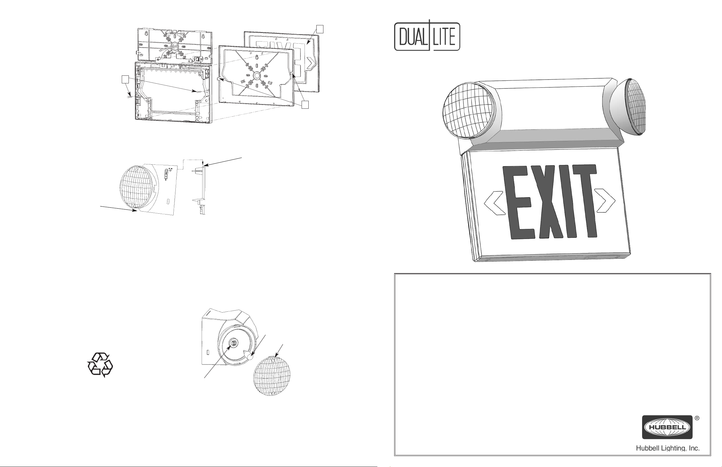
Double Face Applications (Universal Models Only)
1.
Remove safety tabs to free back plate
retainer clips.
2.
Disengage detents on bottom edge of back
plate and press both retainer clips inward to
remove back plate.
3.
Place double face stencil assembly onto
back side of exit frame and snap into place.
1. Dress wires neatly to prevent pinching.
CVT3 Series
3
Combination Emergency Unit/
LED Exit Signs
Installation Instructions
1
2
Final Assembly
2. Align housing slots over
back plate tabs.
3. Pivot housing and
snap closed.
TROUBLE SHOOTING
AC-On Light does not illuminate
• Check AC wiring connections.
Exit Sign does not illuminate
• Check
Emergency lamps do not work
• Battery is shipped disconnected. Connect red lead from PC
• Make sure charger board is properly seated.
• Check wiring connections.
MAINTENANCE
Units should be tested and maintained in accordance with National
Electrical Code and NFP
ommended that emergency lighting units be tested for 30 seconds once
a month and for 90 minutes once a year.
RECYCLING INFORMATION
All thermoplastic parts
are recyclable.
All cartons contain recycled
materials. Please recycle.
NOTICE:
Units contain rechargeable lead-acid or nickel-cadmium batteries
which must be recycled or disposed of properly.
AC wiring and ribbon cable connections.
board to positive (+) battery terminal and
charge before testing.
A 101 Life Safety Code requirements. It is rec-
4. Energize unit. Charge a minimum of
24 hours prior to testing.
5. Press test switch and hold. Aim lamp
heads for proper light distribution.
LAMP
REPLACEMENT
CAUTION: Allow defective lamp to cool completely before
1. Remove plastic lamp lens by prying carefully with screwdriver at
arrow locations.
2. Pull defective lamp from lighting head assembly and unplug lamp
from socket.
3. Plug replacement lamp into socket and install lamp into lighting
head assembly.
4. Re-install lamp lens.
attempting replacement.
Wedge-base
incandescent lamp
Lamp lens
2-pin lamp socket
IMPORTANT SAFEGUARDS
When using electrical equipment, basic safety precautions should always be followed including the following:
READ AND FOLLOW ALL SAFETY INSTRUCTIONS
1. Do not use outdoors.
2. Do not mount near heaters or hot surfaces.
3. Equipment should be mounted in locations and at heights where it will not readily be subjected to tampering
by unauthorized personnel.
4. The use of accessory equipment not authorized by the manufacturer may cause an unsafe condition.
5. Do not use this equipment for other than its intended purpose.
6. Service of this equipment should be performed by qualified service personnel.
Emergency Lighting And Power Equipment For Use In Damp Locations
Damp location listed units are suitable for installation in:
1. Interior locations subject to moderate degrees of moisture, such as some basements, some barns, some
cold-storage warehouses, and the like.
2. Partially protected locations under canopies, marquees, roofed open porches
and the like.
Hubbell Lighting, Inc. Life Safety Products • www.dual-lite.com
Copyright© Hubbell Lighting, Inc., All Rights Reserved • Specifications subject to change without notice. • Printed in U.S.A. 0603192 1/08
SAVE THESE INSTRUCTIONS
Page 2
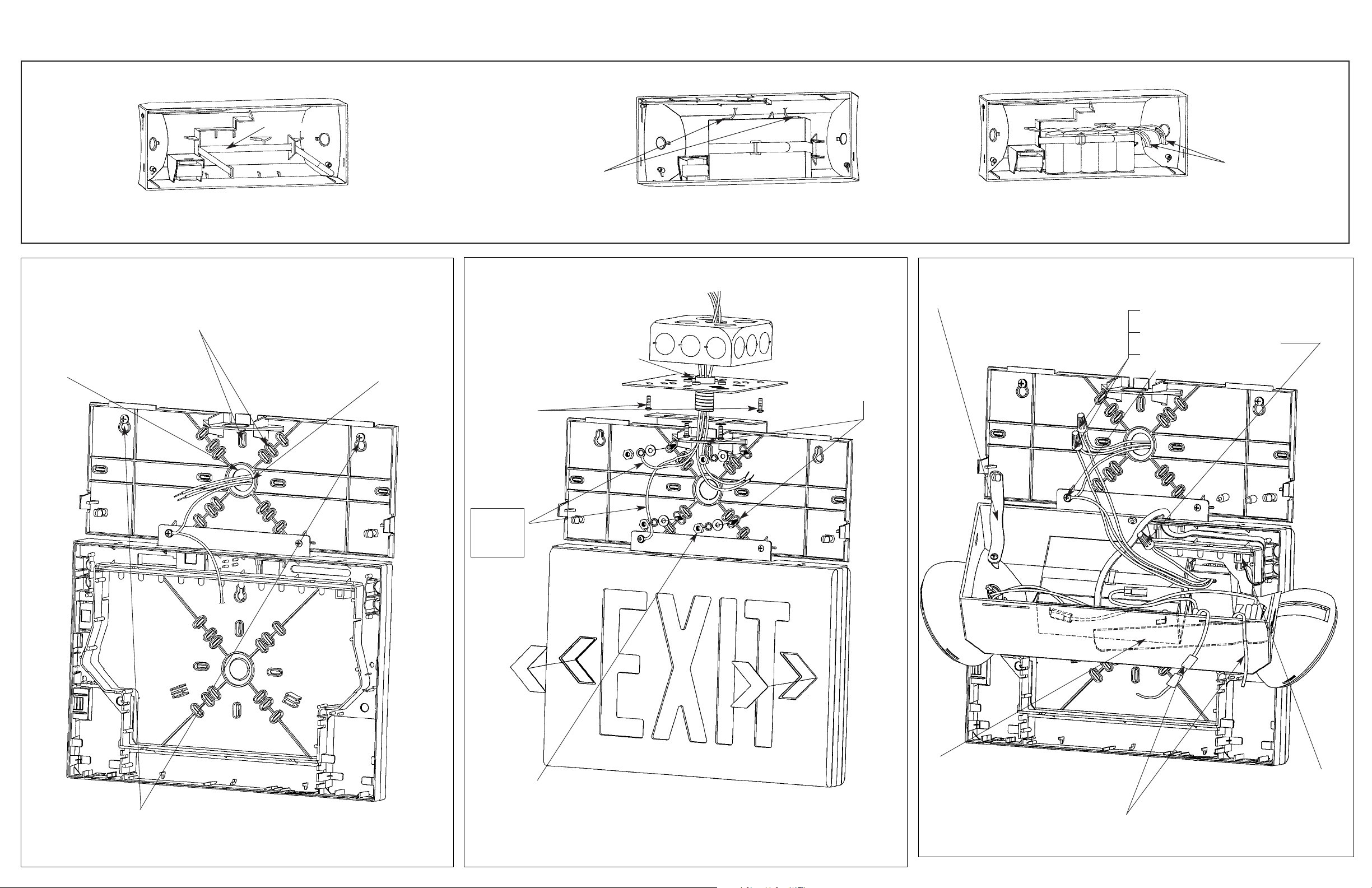
COMBO UNIT INSTALLATION INSTRUCTIONS
Battery Installation and Connections
Battery Security Strap
On models shipped with battery uninstalled, check that battery
security strap is positioned as shown above.
Wall Mount (Back Power Feed)
.
22.
Remove appropriate back plate K.O.s for
electrical box screws.
.
11.
Remove center 3/4” K.O. in unit back
plate.
.
33.
Feed wires through center K.O. and
mount back plate to electrical box.
Battery Connections:
Connect yellow circuit board
lead to battery negative (–)
terminal.
Note: On factory installed
batteries, yellow battery lead
is shipped connected.
Connect red circuit board
lead to battery positive (+)
terminal.
.
11.
Feed building wires through threaded
nipple in ceiling mount base plate and
affix the plate to electrical box using
screws provided with box.
.
22.
Attach unit
mounting bracket
to screw studs in
base plate using
two screws provided.
Lead-Calcium Battery Models
1) Place battery in housing as shown above in front of security
strap.
2) Fasten by tightening security strap.
Ceiling (Top) Mount
.
33.
Remove 4 appropriate
K.O.s in unit back plate
mounting pattern and
3
/4” K.O. in unit back
plate top flange.
Nickel-Cadmium Battery Models
1) Remove double-sided tape protective layer on bottom of
battery assembly.
2) Position battery in housing in front of security strap as
shown above and press battery firmly in place.
3) Fasten by tightening security strap.
Electrical Connections (All Models)
.
11.
Attach unit housing to back plate
by plastic hinge straps provided.
Battery Connections:
Connect battery harness
leads from circuit board to
corresponding leads from
battery assembly
.
22.
Connect building wires to transformer leads.
• Black and white wires for 120V
(Use wire nut to cap off red wire)
• Red and white wires for 277V
(Use wire nut to cap off black wire)
• Brown and blue wires for 220/240V
• Make proper connection to ground
.
.
44.
Using appropriate hardware, mechanically secure unit backplate to wall
surface through keyhole K.O.s
Grounding
pigtail leads
(Refer to
“IMPORTANT”
note below)
.
44.
Place unit back plate onto screw studs in bracket assembly and secure with #8 locking hardware provided. Make sure threaded nipple (used as wiring channel) extends
from base plate through the 3/4” hole in unit back plate top flange.
IMPORTANT: Two grounding pigtail leads are provided. In ceiling mounted applications, both grounding
pigtails must be properly connected to building utility ground for safety reasons.
5
.
5
.
Fire Alarm Panel Option (-FAP)
.
44.
Connect two violet pigtail leads from flasher
module on PC board to appropriate 24 volt AC or
DC fire alarm panel. Wiring connections may be
made inside unit housing or within electrical box.
33..
Connect remote lighting load to yellow and blue (fused)
pigtail leads provided (remote capacity models only).
To complete installation, see Final Assembly instructions on back page.
Route ribbon cable through housing
as shown and plug connector into
LED printed circuit board assembly.
 Loading...