

Page 1

MAINTENANCE DATA
After installation, this enclosure should be inspected at regular intervals. A visual inspection should ascertain that all
bolts are tight and in good condition.
INSTALLATION, OPERATION & MAINTENANCE DATA SHEET
B7NFD COMPACT SERIES IEC DISCONNECT INSTALLATION
For use in Class I, Groups B, C & D, Type 3, 4 & 4X and Class II, Groups E, F & G, and Class III Hazardous
READ THIS SHEET CAREFULLY BEFORE BEGINNING INSTALLATION.
IMPORTANT: This enclosure and device must be installed b y trained , qual if ied a nd competent personnel.
source and lock out.
The mounting location must be flat and provide proper clearance, rigidity and strength to support the enclosure and all
potential for physical injury and property damage.
HUBBELL ELE CTRI CAL PRODUCTS
A Division of HUBBELL INCORPORATED (Delaware)
3940 Martin Luther King Drive
St. Louis, Missouri 63113 USA
Locations, as defined by the Canadian Electrical Code and the National Electrical Code.
Installation must comply with local, state and national regu lat ions, as well as saf ety pract ices for this type of equipment.
WARNING: Electrical power must be OFF during installation, or performing any maintenance. Disconnect primary power
contained devices.
Securely fasten the enclosure to the mounting location. Install sealing fittings, cable glands, unions and/or conduit, using
an approved electrical conducting type lubricant on the threads. The conduit thread connections must be tapered pipe
thread conforming to ANSI B1.20.1. A minimum of (5) full threads engagement is required for all conduit connections.
Conduit sealing fitti ngs m ust be install ed with in 18 inches of the enclosure. Sealing fittings must be approved for the
specific hazardous location where the enclosure is used. All unused conduit openings must be plugged using Killark
“CUP” close-up plugs. Plugs must be tightly installed with a minimum engagement of (5) full threads.
NOTE: If installing a breather and/or a drain, make certain they are suitable for the specific hazardous location where
they are to be used. Some drains/breathers may not comply with Nema 3 & 4 standards. Also, provide a protective
covering to shield the breather and drain during hose-down operations.
For “factory complete” units, follow the instructions at ● and dis-regard the mounting instructions/drawings.
If not a “factory complete” unit, install the IEC Disconnect of your choice per the instructions provide d w ith the device and
the drawings shown on following pages. In the drawings, locate manufacturer of device being installed and note the
specific holes being used to mount device din rail into enclosure box. The din rail numbers correspond with a mounting
location in the enclosure box and are s pec ific to each d evic e. Install din rail in correct location, then install and align
Disconnect and end blocks (where needed) onto din rail, following the drawings provided. Secur e end bl ocks
permanently on both sides of disconnect by using a screw driver and tightening the recessed screws. Cut “square shaft”
(21872) provided, to the over-all length dimension shown in the chart on page 3, for the specific device being used.
(NOTE: smooth out the cut edge of the shaft). Insert the cut shaft, allowing it to rest at the bottom of the device interface
opening and in the orientation shown in the “Disconnect Mounting” pictures that follow.
● Wire the Disconnect as required. Factory installed rotary operator is mounted into cover and aligned at the factory to
interface with Disconnect, once din rail and enclosure cover ar e installed onto box.
▲ Inspect and clean the machined flange flame joint surfaces of both the cover and the box. Surfaces must be smooth,
free of nicks, scratches, dirt or any foreign particle build-up that would prevent a proper seal. Surfaces must seat fully
against each other to provide a proper explosion-proof joint. Clean surfaces by wiping with a clean, lint-free cloth.
Apply a light coating of Killark “LUBG” lubricant to flange surfaces and close the cover. Tighten all cover bolts . Use only
those bolts supplied with the enclosure. Check the bolted joint with a .0015 thick feeler gauge. The gauge must not
enter the joint more than 1/8” at any point. NOTE: Loose bolts or an improper joint can result in an explosion, creating a
cover bolts are still tight; that all conduit connections are intact and free of corrosion, and that the enclosure mounting
P/N KIL00921328 FORM NO. K1328 07/17 ECO-4-010-16 Page 1 of 8
Page 2
procedures should be followed:
WARNING: Before servicing the enclosure, be sure the electrical power is OFF. Disconnect the enclosure from the
primary power source and lock-out.
Loosen cover bolts. Replace any corroded, bent or otherwise damaged bolts with new, factory authorized bolts obtained
Instructions at ▲ on Page 1.
If the enclosure must be opened for servicing, to check or replace internal devices and apparatus, the following
from an authorized Killark distributor.
Open enclosure. Do not use hammer, screwdriver or any prying tool to open cover.
Inspect machined, flame joint flange surfaces. Surfaces must be smooth, free of nicks, scratches, dirt or any foreign
particle build-up that would prevent a proper seal. Should surface be damaged, contact factory. Never attempt to rework
surfaces by sanding, grinding, etc. Surfaces must seat fully against each other to provide a proper explosion-proof joint.
Inspect water exclusion gasket. If gasket is damaged, do not attempt field replacement or repair. Contact a factory
authorized representative for a replacement cover. The damaged gasket can be removed from the cover, and the cover
without gasket can be used until a replacement is obtained. The cover, without gasket, can be safely used in Class I & II
hazardous (classified) locations, however, the enclosure may not be rain-tight or hose-down tight. Follow Installation
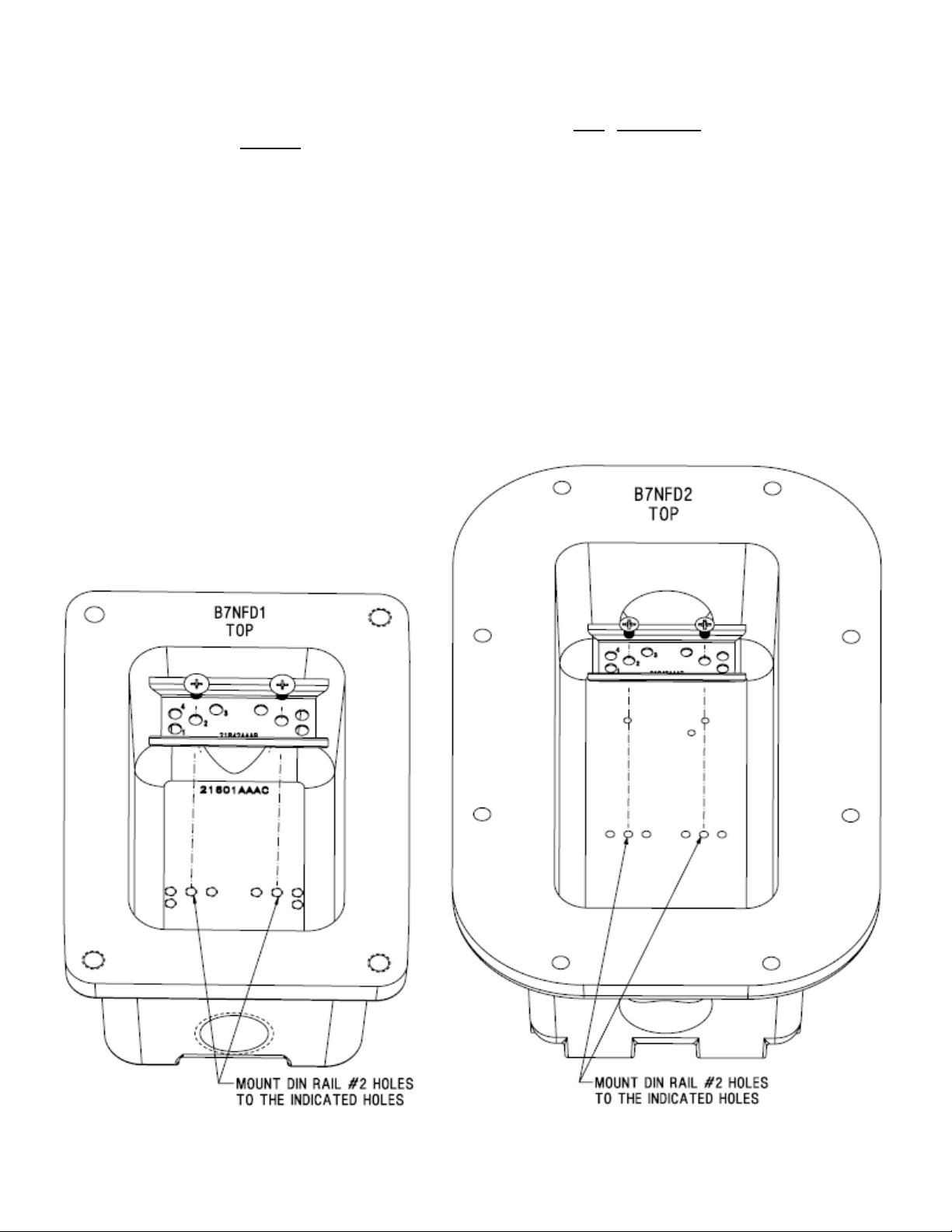
DIN RAIL MOUNTING
P/N KIL00921328 FORM NO. K1328 07/17 ECO-4-010-16 Page 2 of 8
Page 3

DISCONNECT SHAFT LENGTHS – (21873 SQUARE SHAFT)
B7NFD1 - IEC DISCONNECT MOUNTING
P/N KIL00921328 FORM NO. K1328 07/17 ECO-4-010-16 Page 3 of 8
Page 4

B7NFD1 - IEC DISCONNECT MOUNTING
P/N KIL00921328 FORM NO. K1328 07/17 ECO-4-010-16 Page 4 of 8
Page 5

B7NFD1 - IEC DISCONNECT MOUNTING
Align ABB switch per sht.8, then utilize molded mounting hole
(top of switch) and #10-24 hole (provided in b ox) to anchor the
switch in place with a #10-24 x 3/8”L screw.
ABB OT 16F3 / OT 25F3
P/N KIL00921328 FORM NO. K1328 07/17 ECO-4-010-16 Page 5 of 8
Page 6

B7NFD2 - IEC DISCONNECT MOUNTING
Align ABB switch per sht.8, then utilize molded mounting hole
(top of switch) and #10-24 hole (provided in b ox) to anchor the
switch in place with a #10-24 x 3/8”L screw.
ABB OT 40F3 / OT 63F3 / OT 80F3
P/N KIL00921328 FORM NO. K1328 07/17 ECO-4-010-16 Page 6 of 8
Page 7

B7NFD2 - IEC DISCONNECT MOUNTING
P/N KIL00921328 FORM NO. K1328 07/17 ECO-4-010-16 Page 7 of 8
Page 8

B7NFD - IEC DISCONNECT ALIGNMENT
Technical information, advice and recommendations contained in these documents is based on information that Killark believes to be reliable. All the
information and advice contained in these documents is intended for use by persons having been trained and possessing the requisite skill and knowhow and to be used by such persons only at their own discretion and risk. The nature of these instructions is informative only and does not cover all of
the details, variations or combinations in which this equipment may be used, its storage, delivery, installation, check out, safe operation and
maintenance.
There are no warranties, expressed or implied, except that all goods shall conform to their description, subject however to commercial tolerances and
variations.
All sales are made on the express understanding that there are no express warranties other than those contained in a specific agreement between
Seller and Buyer and that there are no implied warranties that the goods shall be merchantable, nor are there any warranties which extend beyond the
description on the face hereof. In the event of the breach of any warranty or alleged breach of any warranty by Killark, the Buyer shall not be entitled to
consequential or incidental damages. The obligation of Killark under its warranty shall be limited to repairing or replacing FOB Kill ark' s plant or all owing
credit at Killark's option, any part or parts which may prove to be thus defective, provided the Buyer(s) gives Killark prompt notice of the defect or
defects. It is expressly agreed and understood that this remedy of repair or replacement or credit at Killark's option is the exclusive remedy of the Buyer
of this product.
Since conditions of use of the product are outside of the care, custody and control of Killark, the purchaser should determine the suitability of the
product for his intended use, and assumes all risk and liability whatsoever in connection therewith.
MAINTENANCE MANAGER: Please record the following information for your records:
(As shown on nameplate)
COMPLETE CATALOG NO. ________________________________________________________________
INSTALLED BY _________________________________________________________________________
DATE OF INSTALLATION _________________________________________________________________
P/N KIL00921328 FORM NO. K1328 07/17 ECO-4-010-16 Page 8 of 8
 Loading...