

Page 1

Pub. 42004-615L2
GAI-TRONICS® CORPORATION
A HUBBELL COMPANY
Model 670-801-EX and 670-801-U L
SmartSeries Amplifiers
for CENELEC Zone 1 and UL Div. 1
Confidentiality Notice
This manua l is provide d sole ly as an operatio nal, installation, and ma inte nance guide and conta ins
sensitive business and t e chnical informatio n tha t is confidentia l and pr opri et ary to GAI- Tronics.
GAI-Tronics retains all intellectual property and other rights in or to the information contained herein,
and such information may only be used in connection with the operation of your GAI-Tronics product or
system. This manu al may not be dis clos e d in any form, in whole or in pa rt, direct ly or i ndir ectly, to a ny
third pa r ty.
Introduction
The assembly described in this manual is an explosion-proof enclosure and intelligent speaker amplifier
designed to be installed in hazardous areas where combustible gases exist or may exist. The extra thick
cast aluminum enclosure, while not gas tight, is designed to withstand repeated internal explosions
without expelling gases hot enough to ignite the external atmosphere. This is accomplished through the
use of a precision-machined enclosure opening flame path that cools the exiting gases to a temperature
below the fla sh poin t of the ext ernal, explosi ve atmosphere.
How to Use the A ssembly/Model
Application
The ha zardou s a rea Smart Ser ies amplifier is designed to provide clear communications even in high noise
areas where explos ive atmos pheres exist o r ma y exi st.
The Model 670-801-EX is BASEEFA approved to CENELEC Standards Ex dib for Zone 1, Group IIC
T5.
The Model 670-801-UL is approved by Underwriters Laboratories for:
• Cla ss 1, Div. 1, Groups C and D
• Class I I, Div. 1, Groups E, F, and G
• Class III, Div. 1
The intelligent SmartSeries
system cab le. It includes micro-controller s tha t are programmed t o :
• Receive and send data messages on the system cable
• Measure ambient noise and adjust speaker level
• Monitor and control optiona l ext ernal equipm e nt
GAI-Tronics Corporation P.O. Box 1060, Readi ng, PA 19607-1060 USA
V
amplifier is designed for use on the GAI-Tronics single party or multi-party
610-777-1374 800-492-1212 Fax: 610-796-5954
ISIT WWW.GAI-TRONICS.COM FOR PRODUCT LITERATURE AND MANUALS
Page 2
Pub. 42004-615L2
Model 670-801-EX and 670-801-UL S martSeries Amplifiers Page: 2 of 15
Hardware Configuration
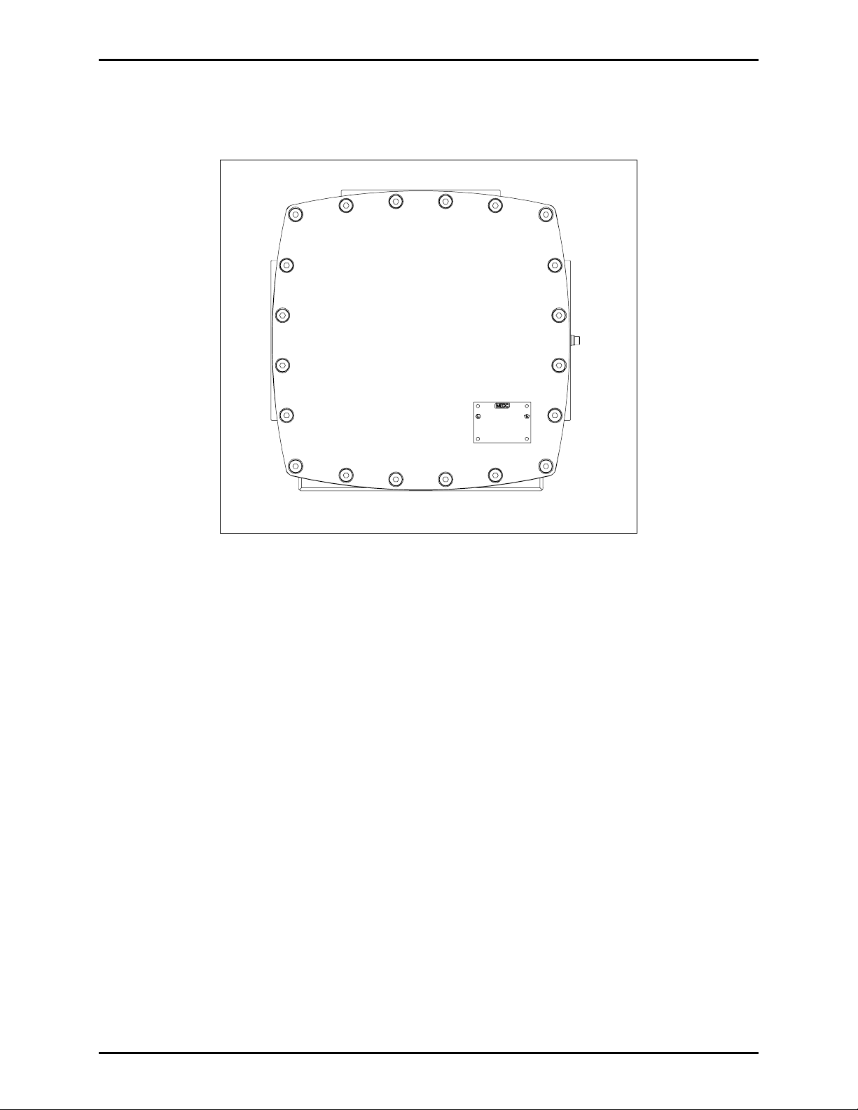
The exterior view of the cast aluminum explosion-proof enclosure is shown in Figure 1 below:
Figure 1. Model 670-801-EX/UL SmartSeries Amplifier
\\s_eng\gtc proddoc s \st andard iom s - current release\42004 instr. manuals \ 42004-615l2. doc
6/97
Page 3
Pub. 42004-615L2
Model 670-801-EX and 670-801-UL S martSeries Amplifiers Page: 3 of 15
Exter nal
The enclosure and cover are fabricated from thick aluminum castings. The cover and the enclosure mate
at machined rims to form the flame path seal. The cover is secured to the enclosure with bolts around the
perimeter. The enclosure entries are as follows:
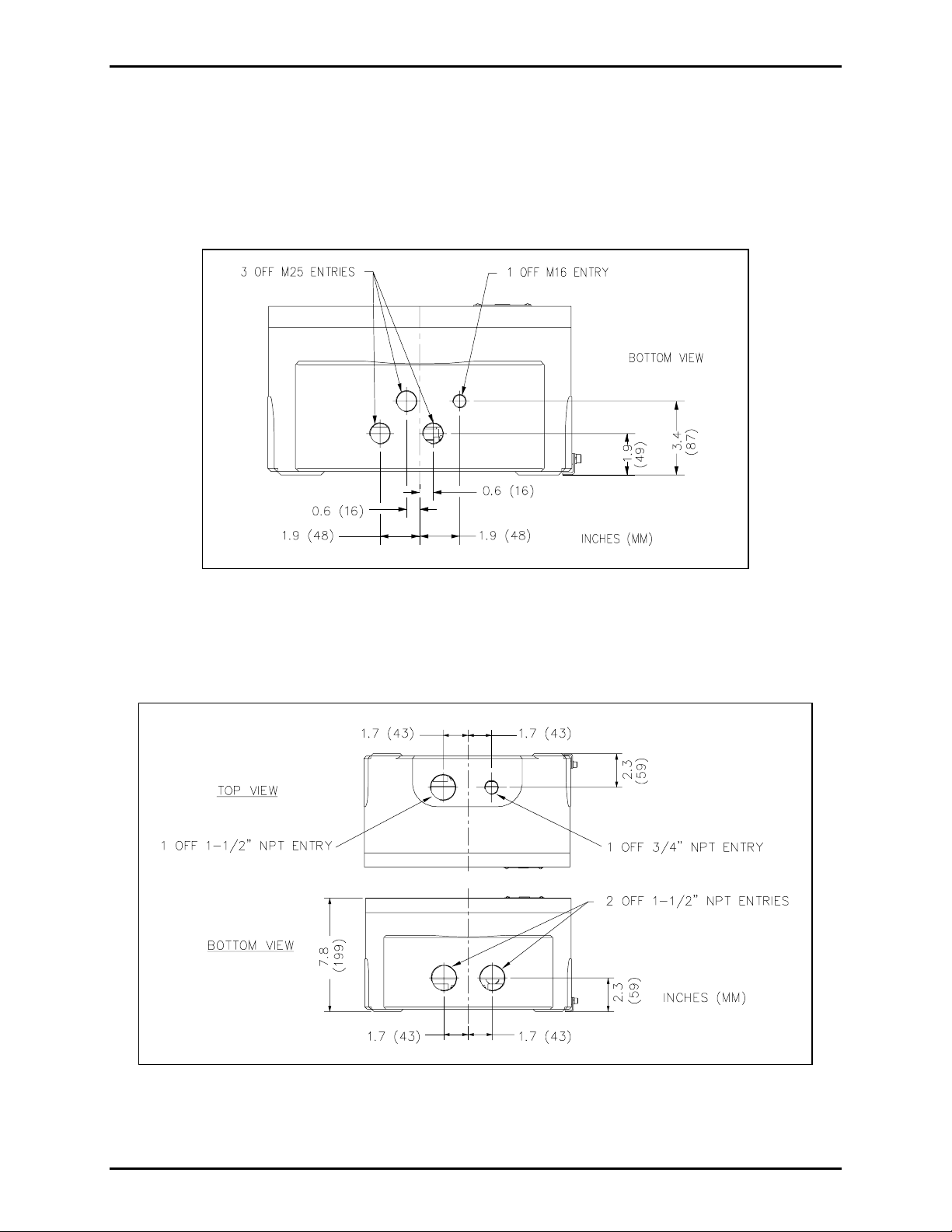
The Model 670-801-EX cable gland entries are shown in Figure 2:
On the base: Three M25 entries, two fitted with plugs; and one M16 entry.
Figure 2. Model 670-801-EX Cable Gland Entries
The Model 670-801-UL conduit entries are shown in Figure 3:
On th e top: O ne 1½- inch N PT ent ry fit ted with a plug, and one ¾- inch N PT ent ry.
On the base: Two threaded 1½-inch NPT entries (one fitted with plug).
Figure 3. Model 670-801-UL Top and Bottom Views
OTE: Ensure any unused openings are sealed with proper fittings per local standards.
N
\\s_eng\gtc proddoc s \st andard iom s - current release\42004 instr. manuals \ 42004-615l2. doc
6/97
Page 4
Pub. 42004-615L2
Model 670-801-EX and 670-801-UL S martSeries Amplifiers Page: 4 of 15
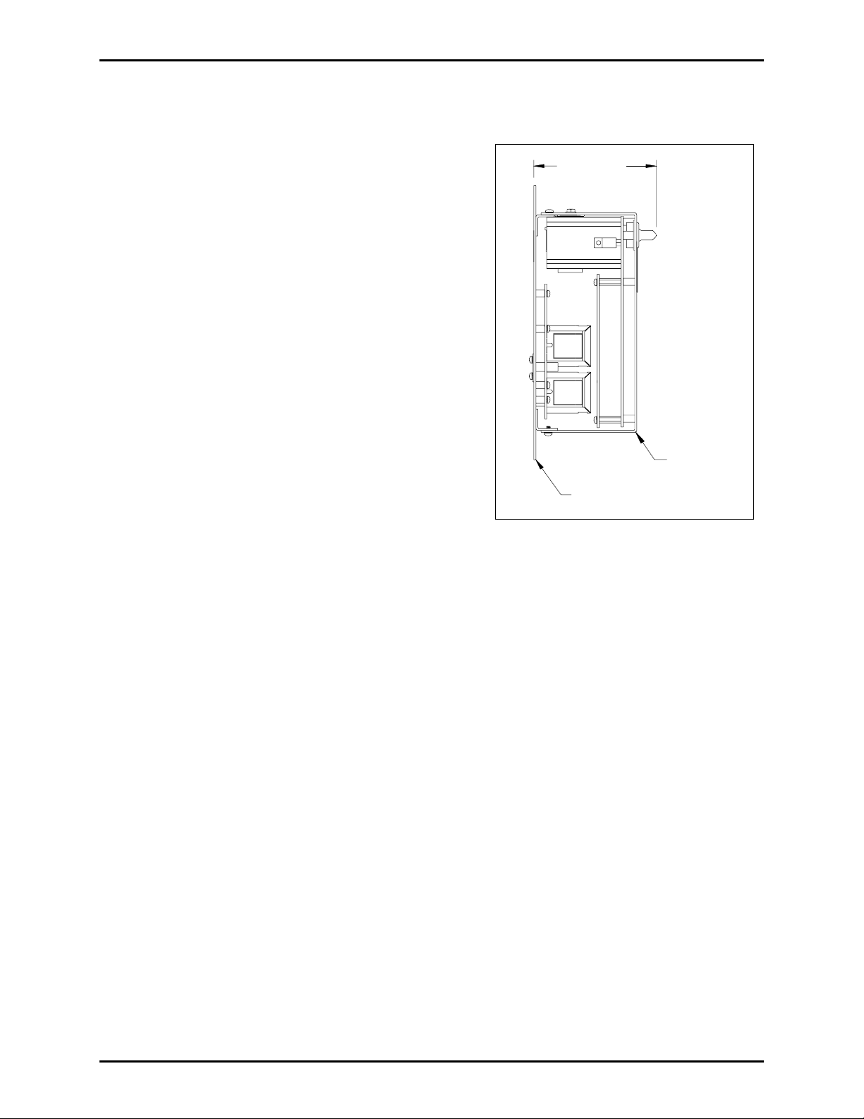
Internal
The SmartSeries amplifier contains the following
components:
• Chassis
3.56 MAX
(90.42)
• Bias Power Supply sub-assembly fixed to the front panel
• Speaker transformer fixed at the top of the chassis
• Base-16 printed circuit board assembly (PCBA) with a
plug at the top, pointing to the rear
• FSK Modem PCBA fixed to the Base-16 PCBA
CHASSIS
GASKET
Figure 4. SmartSeries Amplifier-Side View
\\s_eng\gtc proddoc s \st andard iom s - current release\42004 instr. manuals \ 42004-615l2. doc
6/97
Page 5
Pub. 42004-615L2
Model 670-801-EX and 670-801-UL S martSeries Amplifiers Page: 5 of 15
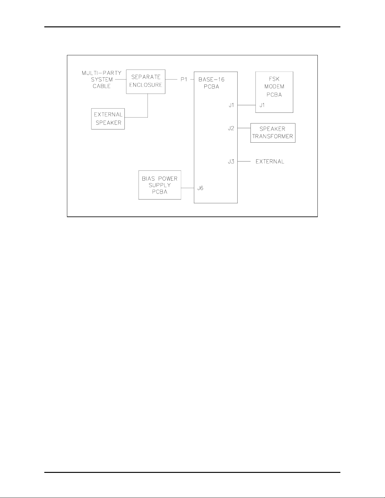
Block Di agram
Figure 5. Model 670-801 Block Diagram
As shown on Figure 5, P1 is the 16-pin male connector located on the back of the Base-16 PCBA. It
plugs into the socket located inside the cast aluminum enclosure. The socket provides connection to the
multi-party cable containing the page/party lines and ac power.
The Base-16 PCBA conducts ac power to the Bias Power Supply PCBA through connector J6 and
receives +5 V dc and +/-15 V dc in return. The Base-16 PCBA uses the bias supplies and also passes
them (as well as control, monitoring, and line signals) to the FSK Modem PCBA via J1, a 24-pin stacking
connector. Connector J2 on the Base-16 PCBA connects the speaker transformer for the station’s external
speaker, and J3 connects optional external devices.
\\s_eng\gtc proddoc s \st andard iom s - current release\42004 instr. manuals \ 42004-615l2. doc
6/97
Page 6

Pub. 42004-615L2
Model 670-801-EX and 670-801-UL S martSeries Amplifiers Page: 6 of 15
Interfaces
The unit interfaces to the multi-party cable and to the external loudspeaker, and auxiliary devices via P1,
a 16-pin connector.
Pin No. Function Description Pin No. Function Description
1
2
3
4
5
6
7
8
PL_L1
PG_L1
MT_L1
AUX0IN*
SPKR_8
SPKR_16
N/C
AC_N
Party line (L1) 9
Page line (L1) 10
Mute (L1) 11
Auxiliary input (0) 12
Speaker (8-ohm) 13
Speaker (16-ohm) 14
No connection 15
AC neutral 16
PL_L2
PG_L2
MT_L2
AUX1IN*
EGND
SPKR_C
N/C
AC_H
Party line (L2)
Page line (L2)
Mute (L2)
Auxiliary input (1)
Ear th ground
Speaker (common)
No connection
AC ho t
The P1 connections for the multi-party cable are separated from the speaker connections within the
enclosure.
\\s_eng\gtc proddoc s \st andard iom s - current release\42004 instr. manuals \ 42004-615l2. doc
6/97
Page 7

Pub. 42004-615L2
Model 670-801-EX and 670-801-UL S martSeries Amplifiers Page: 7 of 15
Installation
Before installing SmartSeries equipment, design the system layout taking into consideration personnel
safety, operational function and convenience, and power cable length. In general, for 115 V ac systems
the total power cable length should not exceed 1 mile (1.6 km), but the length of cable between the
stations is not a crit ic al fa c tor.
Howe ver, it is a good pr actice to r un a separate power feed to each station located i n haza rdous areas.
Wit h a separate feed, individual st atio ns can b e de-en ergized for ser vice or maintenance without a f f ecting
the power supply and operation of the other stations in the hazardous area.
Mounting
N
OTE: The mounting surface must be able to support 55 lbs (25 kg).
1. Remove the front panel. Allow the front panel to hang from the rear of the enclosure by means of
two retaining straps during installation. The straps serve as personnel safety feature and as a
safeguard designed to ensure the front panel flame path is not nicked, dented or otherwise damaged
whi l e mo unt i n g t h e en c l os u re.
2. To maintain the explosion-proof integrity of the enclosure, all mounting hardware is located in non-
intrusive mounting holes under the front panel. The suggested mounting height of the station is 54
inches (137cm). Use standard 1/2-inch socket head cap screws or M12 bolts to secure the enclosure
to a flat mounting surface. See Figure 6 below for mounting hole dimensions.
Figure 6. Shows mounting holes with dimensions.
3. After the enclosure is securely mounted, remove the plug-in amplifier:
• Remove the four screws that secure the amplifier to the standoffs, and retain.
• Pull the amplifier straight toward you to disengage the 16-pin connector from the enclosure.
• Set the amplifier aside in a safe place while completing the installation.
OTE: The follo wing ins tru c tions are provided to ensure co mpliance w i th the a ppr opriate ap proval
N
standards. Select the version that applies to the equipment you have purchased based on approval agency
jurisdiction.
\\s_eng\gtc proddoc s \st andard iom s - current release\42004 instr. manuals \ 42004-615l2. doc
6/97
Page 8

Pub. 42004-615L2
Model 670-801-EX and 670-801-UL S martSeries Amplifiers Page: 8 of 15
UL Version
1. Install the conduits for system and speaker cable and make connection to the enclosure. External
conduits in Class I, Groups C, and D must have gas seals located not more than 18 inches (457mm)
from the amplifier encl osure. External conduits in Clas s II a nd Clas s III areas must also have seals if
the conduit is not dust-tight.
2. Feed the wiring through the conduit and into the enclosure.
3. Make connections by following the wire colors as illustrated in Figure 7. The wire colors correspond
to GAI-Tronics 60029 and 60038 Series system cable and to 60021 for speaker cable.
4. Connect the wires carefully and completely to the compression terminal block. An improper
ter minat ion may result in di minis hed st ation performan ce.
5. Install the amplifier by aligning the 16-pin connector to the enclosure socket and pushing straight in.
Install the four screws retained previously.
6. Lift the front cover and inspect the gasket and mating machined rims for nicks, scratches, or other
dama ge that could co mpromi se the integrity of th e fla me p ath.
7. Secure the front cover in place using the bolts provided. Tighten the bolts alternately with bolts that
are diagonally opposite to ensure that the cover is evenly sealed.
N
OTE: If acoustical feedback occu rs between the sp eak er associated with the amplifier and th e han dset
on a nearby station, the speaker can be muted by moving the violet wire on the enclosure on TB1 to
terminal 7.
EX Version
Follow the mou nting instru ctions desc ribed ab ove.
1. Make up cable core ends as required for connection to the terminal blocks in the enclosure base.
2. Dismantle the outer parts of the 25mm Ex ‘d’ cable gland(s) for the system cable and 16mm Ex ‘d’
cable gland for the speaker cable and thread them onto the cable(s) in the correct order.
3. Feed the cable end(s) into the enclosure through the gland body or bodies and reassemble the outer
gland parts as directed by the manufacturer.
4. Before tightening of the gland assembly, check that the slack in the cable inside the enclosure is
adequate but not excessive.
5. Conn e c t cab le cor es to termina ls fol lowi ng the wire colors as illus tra ted in Figure 7. Th e wire colors
correspond to GAI-Tronics 60071 and 60072 Series system cable and to 60070 for speaker cable.
Connect the wires carefully and completely to the compression terminal block. An improper
ter minat ion may result in di minis hed st ation performan ce.
6. Install the amplifier by aligning the 16-pin connector to the enclosure socket and pushing straight in.
Install the four screws retained previously.
7. Lift the front cover and i nspect the gasket a nd machine d rim f or nicks, sc ratches, or ot her damage that
could co mpromise the int egr i ty of t he flam e path seal .
8. Secure the front cover in place using the bolts provided. Tighten the bolts alternately with bolts that
are diagonally opposite to ensure that the cover is evenly sealed.
\\s_eng\gtc proddoc s \st andard iom s - current release\42004 instr. manuals \ 42004-615l2. doc
6/97
Page 9

Pub. 42004-615L2
Model 670-801-EX and 670-801-UL S martSeries Amplifiers Page: 9 of 15
NOTE: If acoustical feedback occu rs between the sp eaker associated with th e amplifier and the ha n ds et
on a nearby station, the speaker can be muted by moving the violet wire on the enclosure on TB1 to
terminal 7.
Figure 7. Wiring Detail
\\s_eng\gtc proddoc s \st andard iom s - current release\42004 instr. manuals \ 42004-615l2. doc
6/97
Page 10

Pub. 42004-615L2
Model 670-801-EX and 670-801-UL S martSeries Amplifiers Page: 10 of 15
Operation
This unit amplifies page audio for broadcast over external speaker(s).
Adjustments
CAUTION
It is necessary to o pe n the ex p lo s ion-proo f enclosure to make adj us tments. Make adjustments only
when the conditio ns at your facility are such that no
explosive atmospheres ca n be pres ent.
This asse mbly includes one co ntrol that permits adjustments to b e made while the a ssembly is mount e d in
its enclosure but with the bolted cover removed. In addition there are several internal controls that are
accessible only by removing the assembly from its enclosure.
There is a user adjustment for setting the speaker amplifier gain for the SmartVolume™ feature, which
has three components: Minimum Level, Offset Level, and VLC Level. Although they typically require no
adjus tment s, these vol ume le vels can be set with the Us er Level Adju stment control (labe led USER
ADJ). Use a small flat-blade screwdriver with an insulated shaft at least 4 inches long to make
adjustments.
To access th e USER
ADJ contro l, perf orm the follow ing steps:
1. Unbolt and remove the front enclosure cover revealing the speaker amplifier.
2. Loosen (do not remove) the two screws that secure the nameplate.
3. Pivot the nameplate counterclockwise, exposing the access hole.
A guide behind the access hole helps direct the screwdriver to the USER
ADJ control.
4. When you are done with the adjustment, pivot the nameplate clockwise into position, then tighten the
two screws. Re-install the bolted cover.
Minimum Level
The Mi nimum L e vel a djust me nt set s the minimum output of the speaker amplifier. The amplifier can be
set from minimum to full output (12 watts into 8 ohms) in 100 discrete steps, or no output. The factory
default is step 20, providing 4 watts.
To adjust the Minimum Level, perform the following steps:
1. Turn USER
ADJ fully counterclockwise and wait to hear a single beep over the associated speaker.
This switches th e s peak er amplifier into t he Minimum Level ad ju stme nt mod e. I f there is an au dio
signal on the page line when the amplifier enters this mode, you hear it over the associated speaker.
Otherwise, you hear an amplifier-generated test tone.
2. Turn USER
The amplifier r e ma ins in t he Minimum L e v e l adjustment mod e for as long as USER
After USER
ADJ clockwise to t he desired minimum speaker vo lume l e v e l.
ADJ is varying.
ADJ has remained stable for five seconds, the amplifier returns to its normal operating
mode.
\\s_eng\gtc proddoc s \st andard iom s - current release\42004 instr. manuals \ 42004-615l2. doc
6/97
Page 11

Pub. 42004-615L2
Model 670-801-EX and 670-801-UL S martSeries Amplifiers Page: 11 of 15
Offset Level
The Offset Level adjustment causes the speaker amplifier to maintain a set difference between the
ambient level and the speaker output level. The SmartVolume™ feature measures the ambient noise at
th e as sociated speak er and a d ds the Offset Lev e l t o set the sp eaker ampl ifier g ain . This keep s page
announcements louder than the ambient noise. The Offset Level can be set from 0 dB (the speaker output
level is the same as the ambient level) to 49 dB. A speaker should be set for 6 to 10 dB louder than the
ambient noise, so the factory default is 9 dB.
To adjust the Offset Leve l , perform th e followi ng steps:
OTE: There must be enough ambient noise for the amplifier to sense. The exact level depends upon the
N
speaker type, but it is typically approximately 80 dB.
1. Turn USER
ADJ fully clockwise and wait to hear two beeps over the associated speaker.
This switc hes the amplifier i nto the O f f set Level ad justment mo de. If t here is an audio signa l o n the
page line when the amplifier enters this mode, you hear it over the speaker. Otherwise, you hear an
amplifier-generated test tone.
2. Turn USER
The amplifier remains in the Offset Level adjustment mode for as long as USER
After USER
ADJ counterclockwise to the desired speaker volume level.
ADJ is varying.
ADJ has remained stable for five seconds, the amplifier returns to its normal operating
mode.
VLC Level
The VLC Level adjustment sets the speaker amplifier gain for the Page Priority VLC feature to provide
an emergency output level. The amplifier can be set from minimum to full output (12 watts into 8 ohms)
in 100 discrete steps, or to no output. The factory default is step 10, but the System VLC Control feature
is disabled.
To adjust the VLC Level, perform the following steps:
1. Have an assistant page from a station that forces the amplifier being adjusted into VLC mode.
2. Turn USER
ADJ fully counterclockwise and wait to hear two beeps over the amplifier’s associated
speaker.
This switc hes the amplif ier int o the VLC Level adjustment mode.
3. Turn USER
The amplifier remains in the VLC Level adjustment mode for as long as USER
USER
ADJ has remained stable for five seconds, the amplifier returns to its normal operating mode.
ADJ clockwise to the desired speaker volume level.
ADJ is varyi ng. After
Internal Adjustments
This asse mbly include s addit ional internal c ontrol, t h e FSK Transmit Leve l, which aff e cts system
performance. Therefore, only qualified GAI-Tronics personnel with the appropriate test equipment
shou ld make any adjustment s. The function and loc ati on are inclu ded for inf ormation on ly. Tamper ing
with this control may void your warranty.
FSK Transmit Level
The contr ol labe led XMIT LEVEL adjusts the level of the frequency shift keying (FSK) signal transmitted
to the page line.
\\s_eng\gtc proddoc s \st andard iom s - current release\42004 instr. manuals \ 42004-615l2. doc
6/97
Page 12

Pub. 42004-615L2
Model 670-801-EX and 670-801-UL S martSeries Amplifiers Page: 12 of 15
Maintenance
In or der t o verif y and ensure explosion-p roof inte grit y, per form regular preve ntive maintena nce an d
inspection checks on the GAI-Tronics explosion-proof stations. The GAI-Tronics Field Service
Department can f ormulate a service contract to su it s p ecific pr ev entive maintenance needs.
CAUTION
Remove power from the enclosure b efore performing any mainte na nce.
Use the following procedures to ensure reliable operation of your equipment:
1. Remove power from the enclosure.
2. Unbolt the cover. Remove the amplifier from the enclosure.
3. Visu ally check the i nter ior of the enclos ure f or signs of c ontamination. Cont aminati on inside t he
enclosure could mean that t he con duit seals or cab le gla n d seals have been compromised.
4. Ensure the gasket and hardware are in place and in good condition. Reinstall the amplifier and
enclosure cover. Restore power to the unit.
In certain circumstances, it may be necessary to re-terminate some or all of the enclosures in a system.
When this is done, strip the wires back to clean copper, and make wire connections to each terminal.
If contaminants from the plant atmosphere have entered the enclosure, clean the interior. Often, a solvent
contact cleaner is not strong enough to wash away the buildup. If this occurs, try the following steps:
1. Disconnect power from the enclosure.
2. Disconnect all wires from the terminal strip inside the box.
3. Spr ay the interior of the enclosure wit h a heav y-du ty, s urfacta nt-type, water - bas e d industr i al cleaner.
Heavy concentrations of contaminants may be scrubbed with a scrub pad or a soft brush.
4. Rinse the int erior of th e box with a water spray, and blow ou t any exc ess wa ter using c ompressed air.
5. Apply a coating of water-displacement solution followed by contact cleaner and compressed air.
6. Strip wires back to clean copper before reconnections.
7. Reinstall the amplifier and enclosure cover. Reapply the power.
Troubl eshooting
The following suggestions are provided to aid a technician in troubleshooting.
Problem Solution
Feedback during page of nearby
handset s tat io n.
Crosstalk
Use the muting feature in the amplifier enclosure at the terminal
blocks.
One or more system cable pairs may be improperly terminated.
Visually insp ect t h e system cable for accid ental crossing of ca b l e
pairs or grounds.
\\s_eng\gtc proddoc s \st andard iom s - current release\42004 instr. manuals \ 42004-615l2. doc
6/97
Page 13

Pub. 42004-615L2
Model 670-801-EX and 670-801-UL S martSeries Amplifiers Page: 13 of 15
Software Configu ration
The unit has the following versions of software:
PCBA Device Part Number
Base-16 PCBA U2 50086-014
FSK modem PCBA U1 49023-030
The SmartSeries Amplifier has software on U2 of the Base-16 PCBA and on U1 of the FSK Modem
PCBA. This softwa re p rov ides th e fo llowing stand ar d pro g ra m mable features, a ccessible f rom th e SST
Configuration scree n when t h e s tat io n is in an ADVANCE s ystem:
• Page Priority VLC Mode—determines the condition for setting the speaker amplifier output to the
User Page Priority VLC (Volume Level Control) Output Level by comparing the incoming page’s
Page Priority Level with the station’s Page Priority Level (VLC Page Priority). Default setting:
disabled.
• Page Trip Level for Speaker Amplifier—the minimum trip level for detecting a page in progress.
Default setting: 0.44 Vpeak.
• Pass Level for Speaker Amp HC—the minimum expected test tone voltage level for supervision of
the speaker amplifier. Default setting: 0.2 Vpeak.
• Pass Level for Speaker/Wire HC—the minimum expected ambient level for supervision of the
speaker wire. Default setting: 35 dB SPL.
• Smart Party L ine EOL—ena bles or disabl es the st atio n as an e nd-of-li ne device f or supervision of
par ty line 1 , for a stat ion configured e ither as a Smar t Handset Dual Party S elect d e vice or a S ma rt
Handset Party Select device. Default setting: disabled.
• SmartSeries Station RTU Monitored Input Process—selects the input mode for each IDC. Default
setting: disabled.
• SmartS eries Station RTU Pow er Relay Process—select s the re lay group and zo ne associated with an
indicating appliance circuit (IAC). Default setting: disabled.
• Speaker Amplifier Clip Level—the maximum output level of the speaker amplifier. Default setting:
2.16 Vpeak.
• System VLC Control—enables or disables VLC Mode. Default setting: disabled.
• System VLC Group—the group number for VLC operation. Default setting: 0.
• VLC Page Priority—the station’s incoming Page Priority Level. Default setting: 0.
The fo l lowin g standard pr og rammabl e featu res ar e also acces sible f rom th e User L evel Adjustme n t
control on the front panel:
• User Minimum Page Output Level (or Minimum Level)—the minimum page output level of the
speaker amplifier. Default setting: 4 watts.
• User Offset Added to Ambient (or Offset Level)—the amount of gain added to the ambient level so
that an incoming page is not lost in the noise. Default setting: 9 dB.
• User Page Priority VLC Output Level (or VLC Level)—the page output level of the speaker amplifier
when the station is in VLC Mode. Default setting: 1 watt.
\\s_eng\gtc proddoc s \st andard iom s - current release\42004 instr. manuals \ 42004-615l2. doc
6/97
Page 14

Pub. 42004-615L2
Model 670-801-EX and 670-801-UL S martSeries Amplifiers Page: 14 of 15
Specification s
Electrical
Voltage ..............................................................................90 to 140 V ac (120 V ac nominal) 50/60 Hz
Power consumed.........................Zero/maximum signal (12 watts): 15 VA, 10.5 watts/ 53 VA, 34 watts
Speaker Amplif ier
Output.......................................................................... 12 watts minimum, with nominal supply voltage
Output limiter..........................................................................2.16 Vpeak (adjustable via configuration)
Voltage Gain................................................................................................26 dB maximum, adjustable
Frequency Response ........................................................................575-4500 Hz, +0/-3 dB ref. to 1 kHz
Distortion............................................................................................1% max. THD @ 1 kHz, 12 watts
Input Impedance.......................................................................50 k-ohms nominal without FSK modem
16 k-ohms nominal with FSK modem
Audio input from line...........................................1.5 Vrms nominal (depends on distance) from 33 ohm
FSK Modem
FSK output to line.............................................................................0.7 Vrms, 2 Vp-p into 33 ohm load
FSK frequency range ............................................................................................................. . 30-33 kHz
SmartVolume™
Dynamic range (low gain) ........................................................................................ 62 to 100 dBA SPL
Frequency characteristics...............................................................................630 Hz LPF (-6 dB/octave)
Offset (above ambient) User Level Adjust...............................................................................0 to 25 dB
Minimum user adjust ......................................................................................... Off; 85 to 125 dBA SPL
Speaker/Wi re Monitor
Dynamic range (high gain)............................................................................................27 to 65 dB SPL
Frequency characteristics...............................................................................630 Hz LPF (-6 dB/octave)
Fault setpoint............................................................................35 dB SPL (adjustable via configuration)
Note: The measured SPL varies for each speaker type.
Recommended environment ................................................................................. Greater than 50 dB SPL
Mechanical
Dimensions ............................................ 14.4 H × 14.4 W × 7.83 D inches (367 × 367 × 199 mm) overall
Enclosure material........................................................................................................... LM25TF, E poxy
Internal controls ........................................................................................................................Line level
Environmen tal
Operating and storage temperature range..............................................-4º F to +151º F (-20º C to +66º C)
Humidity .................................................................................................................. 95% non-condensing
\\s_eng\gtc proddoc s \st andard iom s - current release\42004 instr. manuals \ 42004-615l2. doc
6/97
Page 15

Pub. 42004-615L2
Model 670-801-EX and 670-801-UL S martSeries Amplifiers Page: 15 of 15
Replaceme nt Parts
Model Number Description
751-801 Amplifier
12555-001 FSK PCBA Kit
12557-001 Base-16 PCBA Kit
12558-001 Bias Power Supply PCBA Kit
12530-001 Transformer/Connector Subassembly
Ref erence Material
Refe rence to Assembly/Model D rawings
Published by Title GAI-Tronics Ref. No.
GAI-Tronics SmartSeries Amplifier Enclosure Outline drawing 222-143
GAI-Tronics SmartSeries Plug-in Amplifier Outline drawing 71846
\\s_eng\gtc proddoc s \st andard iom s - current release\42004 instr. manuals \ 42004-615l2. doc
6/97
Page 16

Warranty
Equipment. GAI-Tronics warrants for a period of one (1) year from the date of shipment, that any
GAI-Tronics equipment supplied hereunder shall be free of defects in material and workmanship, shall
comply with the then-current product specifications and product literature, and if applicable, shall be fit
for the purpose specified in the agreed-upon quotation or proposal document. If (a) Seller’s goods prove
to be defective in workmanship and/or material under normal and proper usage, or unfit for the purpose
specified and agreed upon, and (b) Buyer’s claim is made within the warranty period set forth above,
Buyer may return such goods to GAI-Tronics’ nearest depot repair facility, freight prepaid, at which time
they will be repaired or replaced, at Seller’s option, without charge to Buyer. Repair or replacement shall
be Buyer’s sole and exclusive remedy. The warranty period on any repaired or replacement equipment
shall be the greater of the ninety (90) day repair warranty or one (1) year from the date the original
equipment was shipped. In no event shall GAI-Tronics warranty obligations with respect to equipment
exceed 100% of the total cost of the equipment supplied hereunder. Buyer may also be entitled to the
manufacturer’s warranty on any third-party goods supplied by GAI-Tronics hereunder. The applicability
of any such third-party warranty will be determined by GAI-Tronics.
Services. Any services GAI-Tronics provides hereunder, whether directly or through subcontractors,
shall be performed in accordance with the standard of care with which such services are normally
provided in the industry. If the services fail to meet the applicable industry standard, GAI-Tronics will
re-perform such services at no cost to buyer to correct said deficiency to Company's satisfaction provided
any and all issues are identified prior to the demobilization of the Contractor’s personnel from the work
site. Re-performance of services shall be Buyer’s sole and exclusive remedy, and in no event shall GAITronics warranty obligations with respect to services exceed 100% of the total cost of the services
provided hereunder.
Warranty Periods. Every claim by Buyer alleging a defect in the goods and/or services provided
hereunder shall be deemed waived unless such claim is made in writing within the applicable warranty
periods as set forth above. Provided, however, that if the defect complained of is latent and not
discoverable within the above warranty periods, every claim arising on account of such latent defect shall
be deemed waived unless it is made in writing within a reasonable time after such latent defect is or
should have been discovered by Buyer.
Limitations / Exclusions. The warranties herein shall not apply to, and GAI-Tronics shall not be
responsible for, any damage to the goods or failure of the services supplied hereunder, to the extent
caused by Buyer’s neglect, failure to follow operational and maintenance procedures provided with the
equipment, or the use of technicians not specifically authorized by GAI-Tronics to maintain or service the
equipment. THE WARRANTIES AND REMEDIES CONTAINED HEREIN ARE IN LIEU OF AND
EXCLUDE ALL OTHER WARRANTIES AND REMEDIES, WHETHER EXPRESS OR IMPLIED BY
OPERATION OF LAW OR OTHERWISE, INCLUDING ANY WARRANTIES OF
MERCHANTABILITY OR FITNESS FOR A PARTICULAR PURPOSE.
Return Policy
If the equipment requires service, contact your Regional Service Center for a return authorization number
(RA#). Equipment should be shipped prepaid to GAI-Tronics with a return authorization number and a
purchase order number. If the equipment is under warranty, repairs or a replacement will be made in
accordance with the warranty policy set forth above. Please include a written explanation of all defects to
assist our technicians in their troubleshooting efforts.
Call 800-492-1212 (inside the USA) or 610-777-1374 (outside the USA) for help identifying the
Regional Service Center closest to you.
(Rev. 10/06)
 Loading...