

Hubbel XCS-0S3R6G, XCS-0S3M6G, XCS-0S3L6G, XCS-0S2L3F, XCS-0S2A1 Installation, Operation & Maintenance Data Sheet
...Page 1
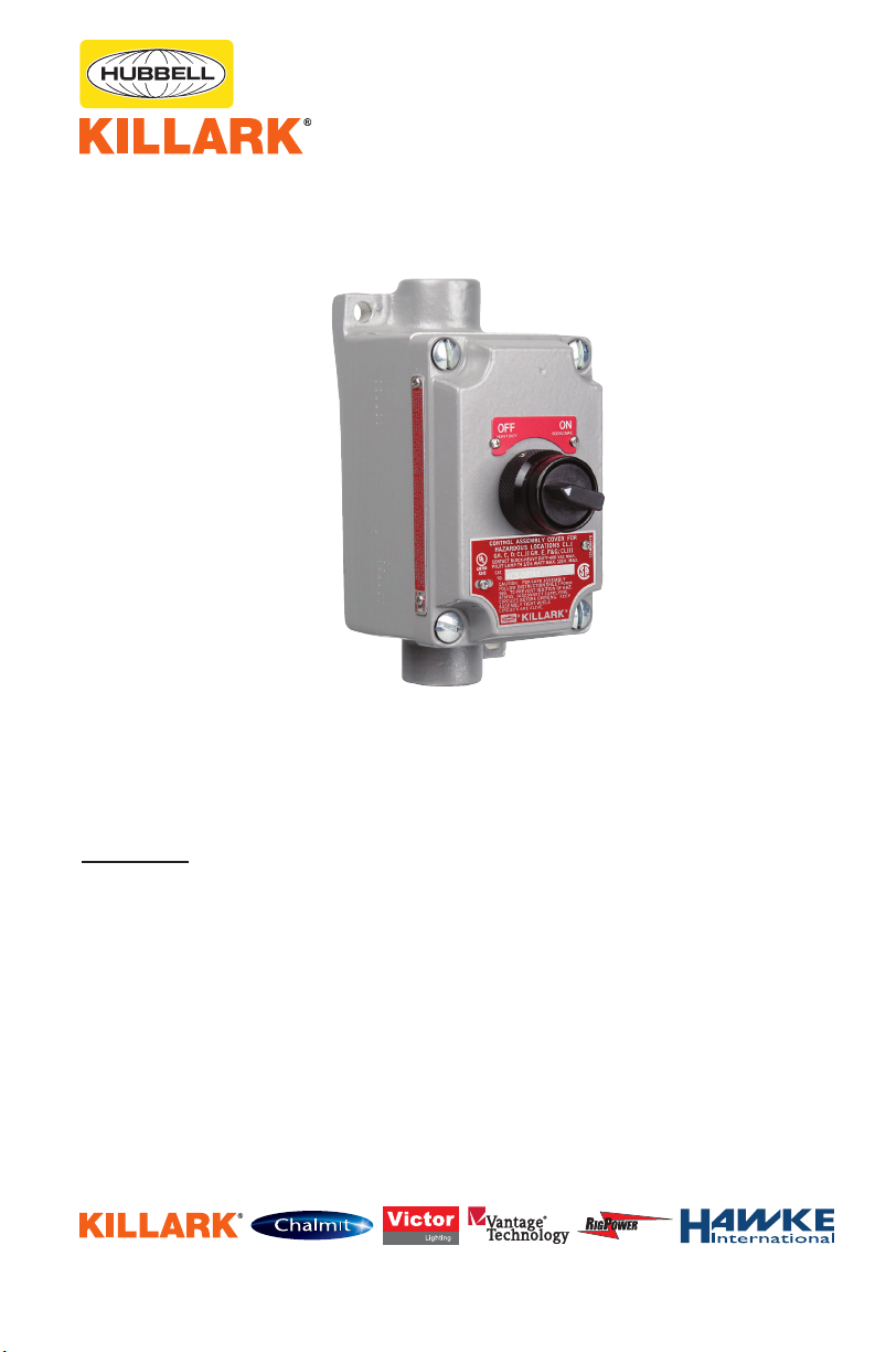
INSTALLATION, OPERATION &
MAINTENANCE DATA SHEET
“XCS-OS” SERIES SPRING RETURN SELECTOR
CLASS I, GROUPS C & D CLASS II, GROUPS E, F, & G
SWITCH ASSEMBLIES.
CLASS III HAZARDOUS LOCATIONS.
“XCS-OS” SERIES SPRING RETURN
SELECTOR SWITCH ASSEMBLIES
CAUTION:
Before installing, make sure you are compliant with area classications, failure to do so may result in bodily injury,
death and property damage. Do not attempt installation until you are familiar with the following procedures. All
installation must comply with the applicable Electrical Code.
Make sure that the circuit is de-energized before starting installation or maintenance.
Verify that the installation is grounded. Failure to ground will create electrical shock hazards, which can cause
serious injury and or death.
Technical information, advice and recommendations contained in these documents is based upon information
that Killark believes to be reliable. All the information and advice contained in these documents is intended for
use only by persons having been trained and possessing the requisite skill and know-how and to be used by
such persons only at their own discretion and risk. The nature of these instructions is informative only and does
not cover all of the details, variations or combinations in which this equipment may be used, its storage, delivery,
installation, check out, safe operation and maintenance. Since conditions of use of the product are outside of the
care, custody and control of Killark, the purchaser should determine the suitability of the product for his intended
use, and assumes all risk and liability whatsoever in connection therewith.
3940 Dr. Martin Luther King Drive
St. Louis, MO 63113
P/N 00901306 FORM NO. K0564 R09/08 ECO-3-037-08 Page 1 of 5
Page 2

1. DIRECTIONS FOR INSTALLATION
2. OPERATION
CAUTION: Before beginning installation, make
sure that the supplying circuit is turn OFF.
Be sure the ame paths (cover to box mating
surfaces and threaded openings) do not become
damaged.
Do not install in a corrosive area which will
attack the “copper free” aluminium alloys or
stainless steel shaft unless the casting and
parts have been protected against the specic
corrosive environment.
Do not locate in areas where dust, ice, snow,
or other substance will accumulate and thereby
impair the rotary operation of the device.
XCS-0S device are for surface mounting in
hazardous atmospheres as dened by NEC
article 500. They contain an electrical device
and must be sealed from the conduit system as
required by article 501-5. Type “ENY”, “EY” or
“EYS” series (or equivalent).
Install sealing tting as required in class l & ll
areas.
(Note: For class l (5) and class ll(3-1/2) full
threads engagement are required).
The conduit threads should be lubricated with a
non-electrical insulating lubricant, or pipe joint
compound which will not promote corrosion or
chemically attack aluminium.
After the conduit system has been properly
installed, pull the wires and make the electrical
connections as required.
The electrical circuits and ground continuity
should be checked with an instrument approved
for the area.
The mechanical action of these devices is
rotary.The electrical action is dependent
upon the cam conguration and the
contact block used. (See chart). An
accessory locking device may be used
with the standard selector switch without
alternations.
3. MAINTENANCE
The Shaft should be lubricated
occasionally to prevent binding. Use
Killark “LUBG” (general purpose ) or Killark
“LUBT” (high temperature) lubricants.
Flame Path machined on cover & box such that
a 0.0015” Feeler gauge will not enter more than
1/8” when fully assembled & bolted to box. Care
must be taken that surface is not damaged.
3940 Dr. Martin Luther King Drive
St. Louis, MO 63113
P/N 00901306 FORM NO. K0564 R09/08 ECO-3-037-08 Page 2 of 5
Page 3
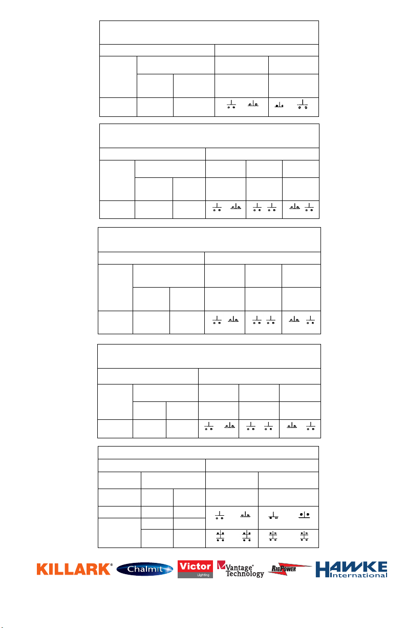
XCS SPRING RETURN SELECTOR SWITCH XCS-0S ARE HEAVY-DUTY,.
Two Position Spring Return to Left 600 VAC RATED.
CATALOG NUMBER
TWO POSITION DIAGRAM
COVER WITH
DEVICE
COMPLETE UNITS ( BOX &
COVER)
LEFT POSITION
RIGHT POSITION
DEAD - END
FEED - THRU
LEFT
RIGHT
BLOCK
BLOCK
LEFT RIGHT
BLOCK BLOCK
XCS-0S2L3F
XCS-42S2L3F
XCS-45S2L3F
XCS SPRING RETURN SELECTOR SWITCH
Three position Spring Return to Center From Right or Left
CATALOG NUMBER
THREE POSITION DIAGRAM
COVER
WITH DEVICE
COMPLETE UNITS ( BOX &
COVER)
LEFT POSITION
CENTER
POSITION
RIGHT
POSITION
DEAD - END
FEED -THRU
LEFT RIGHT
BLOCK BLOCK
LEFT RIGHT
BLOCK BLOCK
LEFT RIGHT
BLOCK BLOCK
XCS-0S3M6G
XCS42S3M6G
XCS45S3MG
XCS SPRING RETURN SELECTOR SWITCH
Three Position Spring Return to Center From Right, Maintain in left
CATALOG NUMBER
THREE POSITION DIAGRAM
COVER WITH
DEVICE
COMPLETE UNITS (BOX
&COVER)
LEFT POSITION
CENTER
POSITION
RIGHT
POSITION
DEAD - END
FEED - THRU
LEFT RIGHT
BLOCK BLOCK
LEFT RIGHT
BLOCK BLOCK
LEFT RIGHT
BLOCK BLOCK
XCS-0S3L6G
XCS-42S3L6G
XCS-045S3L6
G
XCS SPRING RETURN SELECTOR SWITCH
Three Position Spring Return to Center From Left, Maintain in Right
CATALOG NUMBER
THREE POSITION DIAGRAM
COVER WITH
DEVICE
COMPLETE UNITS ( BOX &
COVER)
LEFT POSITION
CENTER
POSITION
RIGHT POSITION
DEAD - END
FEED-THRU
LEFT RIGHT
BLOCK BLOCK
LEFT RIGHT
BLOCK BLOCK
LEFT RIGHT
BLOCK BLOCK
XCS-0S3R6G
XCS-42S3RG
XCS045S3R6G
XCS TWO POSITION SELECTOR SWITCH (MAINTAINED)
CATALOG NUMBER
TWO POSITION DIAGRAM
COVER WITH
DEVICE
COMPLETE UNITS ( BOX &
COVER)
LEFT POSITION
RIGHT POSITION
DEAD - END
FEED -THRU
LEFT RIGHT
BLOCK BLOCK
LEFT RIGHT
BLOCK BLOCK
XCS-0S2A1
XCS-1S2A1
XCS-4S2A1
XCS-0S2A5
XCS-2S2A1
XCS-5S2A1
XCS-42S2A5
XCS-45S2A5
3940 Dr. Martin Luther King Drive
St. Louis, MO 63113
P/N 00901306 FORM NO. K0564 R09/08 ECO-3-037-08 Page 3 of 5
Page 4
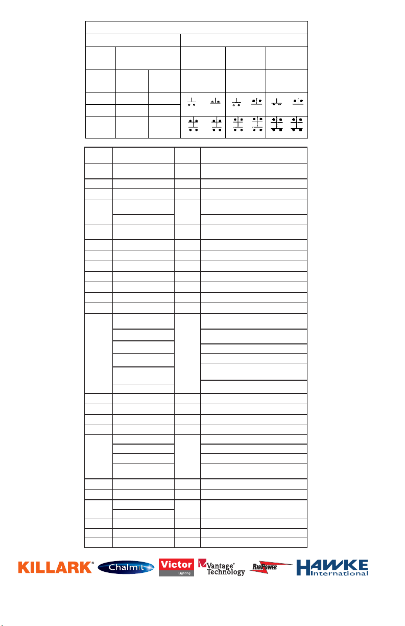
XCS THREE POSITION SELECTOR SWITCH (MAINTAINED)
CATALOG NUMBER
THREE POSITION DIAGRAM
COVER
WITH
DEVICE
COMPLETE UNITS ( BOX &
COVER)
LEFT POSITION
CENTER
POSITION
RIGHT POSITION
DEAD - END
FEED -THRU
LEFT RIGHT
BLOCK BLOCK
LEFT RIGHT
BLOCK BLOCK
LEFT RIGHT
BLOCK BLOCK
XCS-0S3C4
XCS-1S3C4
XCS4S3C4
XCS-2S3C4
XCS-5S3C4
XCS0S3C5
XCS-42S3C5
XCS45S3C5
ITEM
NO.
1
XCS-OK SERIES
P/N
0857BAALB
QTY. DESCRIPTION
1
G SERIES OPERATOR BODY
2 06011300B 1 1/8X5/8 SS SPRING PIN
SEE
BOM
SEE
BOM
1
XCS-OK /OS COVER
2-POS. MAINTAINED PLATE
1
1
1
1
1
1
3
2
8564-KX KNOB-SHAFT ASSY
SELECTOR SWITCH INDEX SPRING
S-217-1 BALL CGE LEVER
W-T 5100-31 RETAINING RING
3/4 STEEL LOCKNUT (UL)
10385SPACER PLATE
6-32X. 375 BHNP SCREW
6 EXT - TH LOCKWASHER
2-POS. “A“ CAM (8505)
3-POS. “B“ CAM (11586)
3-POS. “C“ CAM (11587)
3-POS. “D“ CAM (11588)
3-POS. “E“ CAM (11589)
3-POS. “G“ CAM (11590)
1
6 PLTD SPLIT LOCKWASHER
1
1
6 PLTD FLAT WASHER
G SERIES CAP
3 17969ABAM
4
5
17791AAAB
17791BAAB 3-POS. MAINTAINED PLATE
09589ACHB
6 17786AAAB
7 0103249B
8 068282
9 LN2
10 0608130B
11 16504AAAB
12 0860750B
0106775B
0106600B
13
0106500B
0106550B
0106650B
0106750B
14 08606508
15 0860751B
16 0152195B
17 14510WAHB 1 6-32X1/8 SS KNPT SET SCREW
0226100B
18/19
0226200B CONTACT BLOCK, NORM. CLOSED
0226300B CONTACT BLOCK, N.O. EARLY MAKE
0226075B
20 0540051B
21 14242AADB
22
0547320B SEE
0547330B
SEE
BOM
BOM
1
1
CONTACT BLOCK, NORM. OPEN
CONTACT BLOCK, N.C. LATE
BREAK
COMPONENT NAMEPLATE
COMPONENT NAMEPLATE
G SERIES NAMEPLATE
23 12140AAFB 1 G SERIES NAMEPLATE
24 16489AAAB 8 #2X. 188 SL PAN HD SCREW
25 00891896 1 COVER SCREW SUBASSEMBLY
3940 Dr. Martin Luther King Drive
St. Louis, MO 63113
P/N 00901306 FORM NO. K0564 R09/08 ECO-3-037-08 Page 4 of 5
Page 5
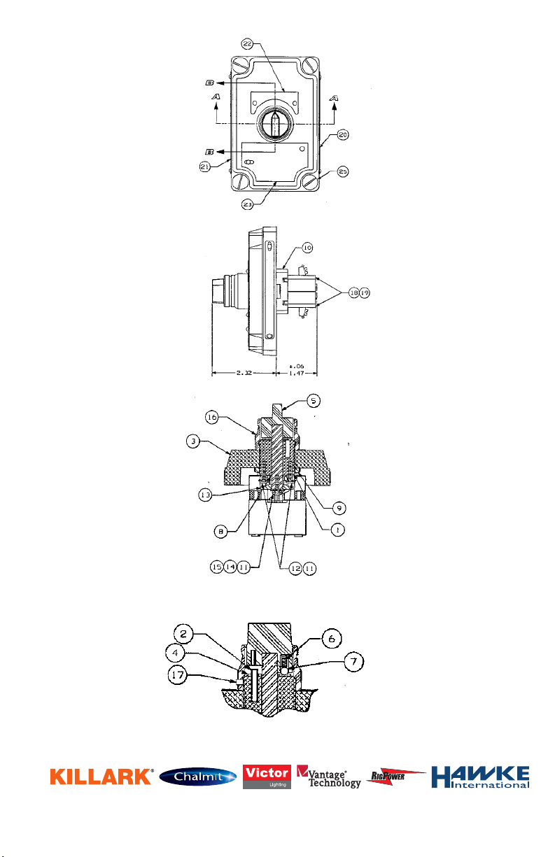
SECTION A * A
SECTION B * B
3940 Dr. Martin Luther King Drive
St. Louis, MO 63113
P/N 00911850 FORM NO. KO687 R01/06 ECO-8-021-04 Page 5 of 5
 Loading...