

Page 1
®
®
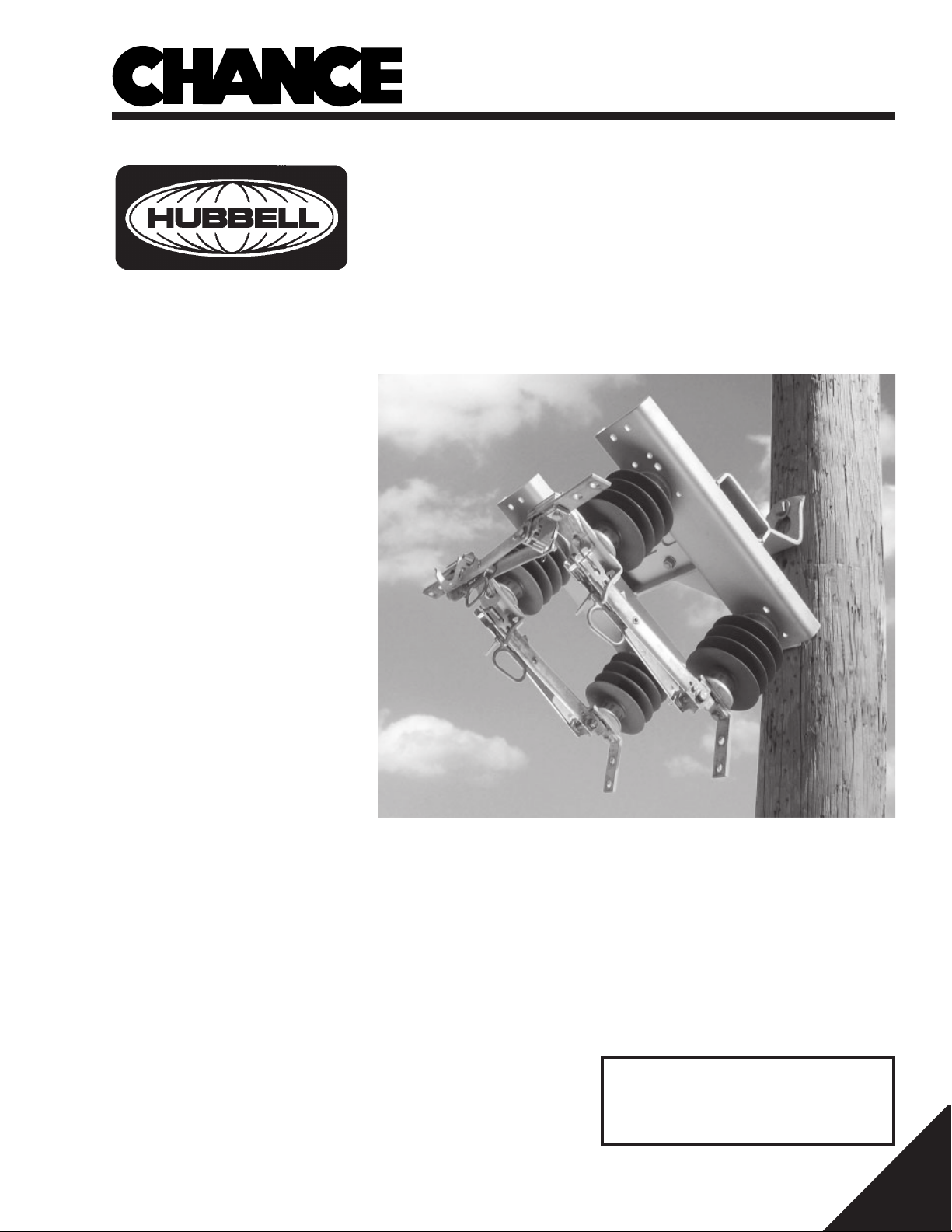
Type BP3
3-Pull
Installation, Operation and
Maintenance Manual
POWER SYSTEMS, INC.
By-Pass Switch
for Distribution Switching
HUBBELL POWER SYSTEMS, INC.
210 North Allen Street
Centralia, MO 65240-1395 U.S.A.
Telephone: (573) 682-5521
Printed in U.S.A.
P805-0011 Rev. A
©
2002 Hubbell Power Systems, Inc., 210 North Allen Street, Centralia, MO 65240 U.S.A.
IMPORTANT!
Keep this manual readily
available for future reference.
1 of 12
Page 2
Warnings
!
DANGER
Electrical equipment contains hazardous voltages and high
speed moving parts. Contact with these hazards will cause
death, serious personal injury or damage equipment.
Only qualified personnel shall install, operate and maintain this
equipment. Always properly ground equipment and lock out
electric power (de-energize) before maintenance. Using nonspecified/unauthorized parts or components to repair equipment, or tampering with safety devices/systems will result in
dangerous conditions which can cause death, severe personal
injury or damage to equipment. Take note of and follow all safety
instructions contained in this installation, operation and maintenance manual.
IMPORTANT
These installation, operation and maintenance instructions do not claim to cover all details or variations in
equipment. Nor do they provide for all possible conditions encountered while installing, operating or maintaining
this equipment. If further information is desired or needed to address any particular installation, operation or
maintenance problem not covered in this document, contact your authorized factory representative.
The information in this document does not relieve the user from exercising good judgment in selecting equipment for suitability of application. Nor does it relieve the user from using sound practices in installation, operation
and maintenance of the equipment purchased.
Note: Because CHANCE has a policy of continuous product improvement, we reserve the right to change
design and specifications without notice. Should a conflict arise between the general information in this document and the contents of drawings or supplementary material, or both, the latter shall take precedence.
QUALIFIED PERSON
For the purpose of this manual, a qualified person is:
(a) familiar with the installation, operation and maintenance of the subject equipment and the hazards
involved with its installation, operation and maintenance.
(b) trained to de-energize, clear, ground, and tag circuits and equipment in accordance with established
safety practices.
(c) trained in the proper care and use of protective equipment such as rubber gloves, hard hat, safety glasses
or face shields, flash clothing, etc., in accordance with established utility safety practices.
(d) trained to render first aid.
SUMMARY
The information in this document does not claim to cover all details or variations in equipment, nor to provide for
every possible contingency encountered with installation, operation, or maintenance. Should further information
be needed or problems arise that are not covered sufficiently, contact your factory representative.
The contents of this document are not part of, nor do they modify, any prior or existing agreement, commitment
or relationship. CHANCE terms and conditions of sale constitute the entire obligation of CHANCE. The warranty
in the terms and conditions of sale is the sole warranty of CHANCE. Any statements in this document do not
create new warranties or modify any existing warranty.
2 of 12
P805-0011 Rev. A
©
2002 Hubbell Power Systems, Inc., 210 North Allen Street, Centralia, MO 65240 U.S.A.
Page 3
Overview
Qualified Person
Only qualified trained and competent
personnel that understand proper safety
procedures must select, install and service
this equipment.
Read and understand these instructions before installing, operating or maintaining this
equipment.
This guide is not a substitute for adequate
training and experience in safety procedures
for this type of equipment.
Signal Words
The signal words “DANGER,” “WARNING”
and “CAUTION” (along with their assigned
symbol) throughout this manual indicate the
degree of hazard the user may encounter.
These symbols and words are defined as:
!
DANGER
▲
DANGER indicates an imminently hazardous
situation which, if not avoided, will result in
death or serious injury.
Function
These products are non-loadbreak disconnect switches designed to provide a means
for by-passing, disconnecting and isolating
reclosers or similar devices on the electrical
distribution system.
General
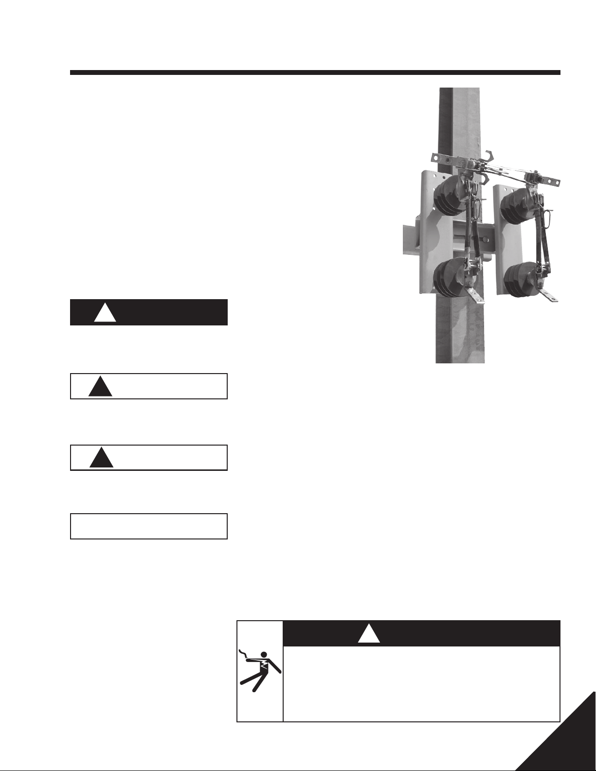
The BP3 By-Pass Switch is a single-phase
3-blade, 3-pull, hookstick operated switch. It
is used for manually disconnecting a
recloser without interrupting normal electrical service. Standard variations are:
1. Right or left opening by-pass blade
operation
2. Switch mounting
3. Terminal connections
4. Loadbreak hooks on disconnect blades.
The BP3 switch has no inherent current
making or breaking capacity. The by-pass
blade includes a hook for use with a loadbreak tool. The BP3 has no deadending provisions.
Specifications
!
WARNING
WARNING indicates a potentially hazardous
situation which, if not avoided, could result in
death or serious injury.
!
CAUTION
CAUTION indicates a potentially hazardous
situation which, if not avoided, may result in
minor or moderate injury.
CAUTION
CAUTION used without the safety alert symbol indicates a potentially hazardous situation
which, if not avoided, may result in property
damage.
Select the proper BP3 switch for each installation with consideration to voltage, continuous current, short time current withstand, lightning impulse withstand and variations. If there
is concern about the use of this switch as rated,
consult your supervisor before installation.
• Nominal voltage ratings of 14.4 kV, 25
kV or 34.5 kV (model dependent)
• Lightning impulse peak withstand ratings
of 110 kV, 125kV or 150 kV (model
dependent)
• Continuous current rating of 600
amperes
• Short time current withstand rating:
25 kA symmetrical, 1 second
65 kA peak
Product
The products covered by this manual are
the BP3 3-Pull overhead by-pass switches
for medium voltage electrical distribution
switching.
These products are designed for distribution
switching only at their rated capacities. They
cannot be field modified for capacities other
than what was shipped with the units. If a
different capacity is desired, contact your
supervisor or factory representative to secure the appropriate unit.
P805-0011 Rev. A
©
2002 Hubbell Power Systems, Inc., 210 North Allen Street, Centralia, MO 65240 U.S.A.
Hazardous voltage.
Will cause severe personal injury, death, or property damage.
Only qualified personnel should work on or around this equipment after
becoming thoroughly familiar with this document and other publications
regarding this equipment.
Switch Variations
1. Right or Left By-Pass Blade Opening
Right or left by-pass blade opening may be
specified. A right opening by-pass blade
opens to the right of the operator when
standing in front of the switch. A left opening by-pass blade opens to the left. Illustrations in this manual show only right by-pass
blade opening. Left by-pass blade opening
will be opposite as shown but does not
change installation or operation procedures.
!
DANGER
3 of 12
Page 4
Overview
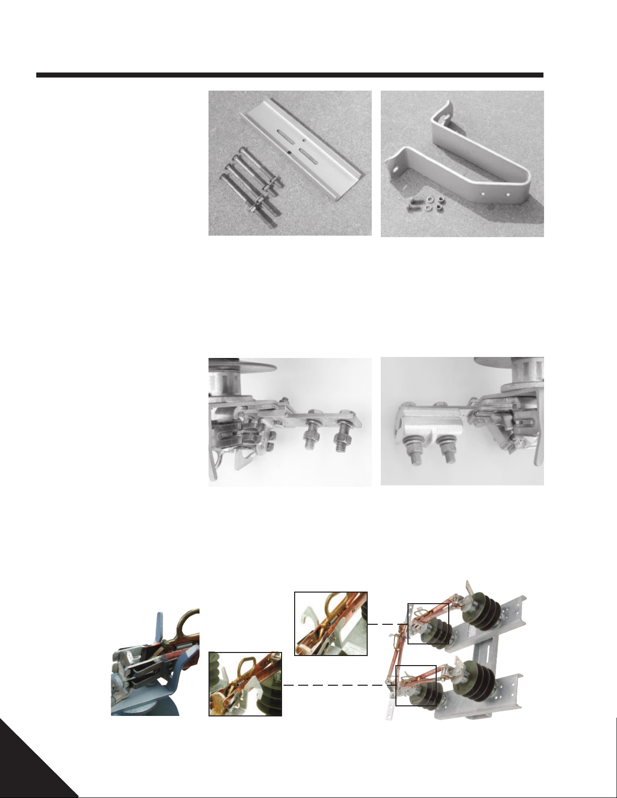
2. Switch Mounting (3 variations)
• No Mounting Bracket (standard)
Provides holes and slots in the switch base
for direct base to a vertical structure mounting without the use of a back strap or pole
mounting bracket. The structure must be
drilled to match the base mounting holes or
slots. The user supplies the mounting hardware.
3. Terminal Connectors (3 variations)
• No Terminal Hardware (standard)
The user supplies the terminal connectors
and mounting hardware.
• Back Strap
Provides a galvanized steel back strap and
hardware for vertical structural applications.
Mounting hardware supplied consists of two
each of 1/2" diameter by 8" long and 10"
long carriage bolts with square nuts and flat
washers.
• Captive Hardware
Provides
less bolt secured into each terminal pad
hole. Each bolt is supplied with a hex nut
and lock washer. Terminal connectors supplied by the user.
1
/2" diameter by 13/4" long stain-
•Pole Mounting Bracket
Provides a galvanized steel bracket for
wood pole mounting. Hardware is supplied
to attach the switch to the bracket. The user
supplies the bracket-to-pole hardware. If the
utility pole is other than a wood pole, contact your factory representative.
•Terminal Connectors
Four fortified cadmium plated aluminum parallel groove terminal connectors (ATC1343)
with terminal pad mounting hardware are
supplied. The connectors accommodate
conductor sizes ranging from No 2 solid
copper thru 500 MCM copper or aluminum.
4. Loadbreak Hooks on Disconnect Blades (2 variations)
• Blade Guides
Provides non-loadbreak blade
guides on disconnect blades.
4 of 12
(standard)
• Loadbreak Hooks
Provides single-sided loadbreak hooks on disconnect blades.
P805-0011 Rev. A
©
2002 Hubbell Power Systems, Inc., 210 North Allen Street, Centralia, MO 65240 U.S.A.
Page 5
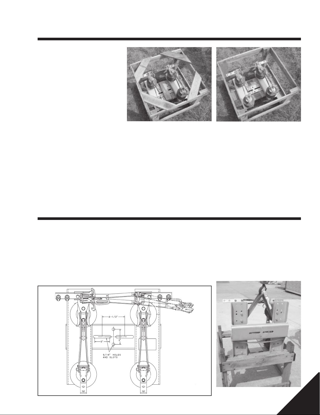
Receiving & Handling
Inspect Packaging
• Upon receipt, immediately inspect
packaging for signs of damage
• Start inspection with the packaging
material and proceed to the equipment
within
• Look for concealed damage
• If damage is found, note damage on Bill
of Lading prior to accepting delivery, if
possible
Note: Documentation of visible shipping
damage can determine the outcome of
any damage claim. Immediately notifying
the carrier of concealed damage is
essential to resolving or minimizing
unsettled claims. Immediately file your
claim and notify your factory
representative.
Unpack Switch
• Place shipping crate on stable, level
surface near the utility pole
• Remove the four angled top boards from
the shipping crate
• Remove any options included
• Remove the clamping board from across
the switch base
Switch Installation
Install Switch
The BP3 By-Pass switch is available in three
mounting arrangements. It may be obtained
with no mounting bracket, with a back strap
or with a bracket for wood pole mounting.
Select your application from the descriptions
below and install the switch accordingly.
Structure Application
• Refer to Figure 1
• Determine the switch mounting location
on the structure
• Provide a minimum of two 9/16" diameter
mounting holes in the structure matching
the hole or slot patterns as shown in the
switch base detail
• Leave switch on its pallet until ready to
install
• Compare switch with the photo to be sure
all items have been included
• Contact your factory representative if any
parts are missing
• If desired, the crate may be turned over
and used as a work table to facilitate
assembly and slinging of the switch.
• Secure lifting sling as shown below
• Using your company’s standard practice,
hoist the switch into position
• Attach the switch to the structure with 1/2"
diameter user supplied mounting hardware and torque according to your company standards.
Figure 1
P805-0011 Rev. A
©
2002 Hubbell Power Systems, Inc., 210 North Allen Street, Centralia, MO 65240 U.S.A.
5 of 12
Page 6
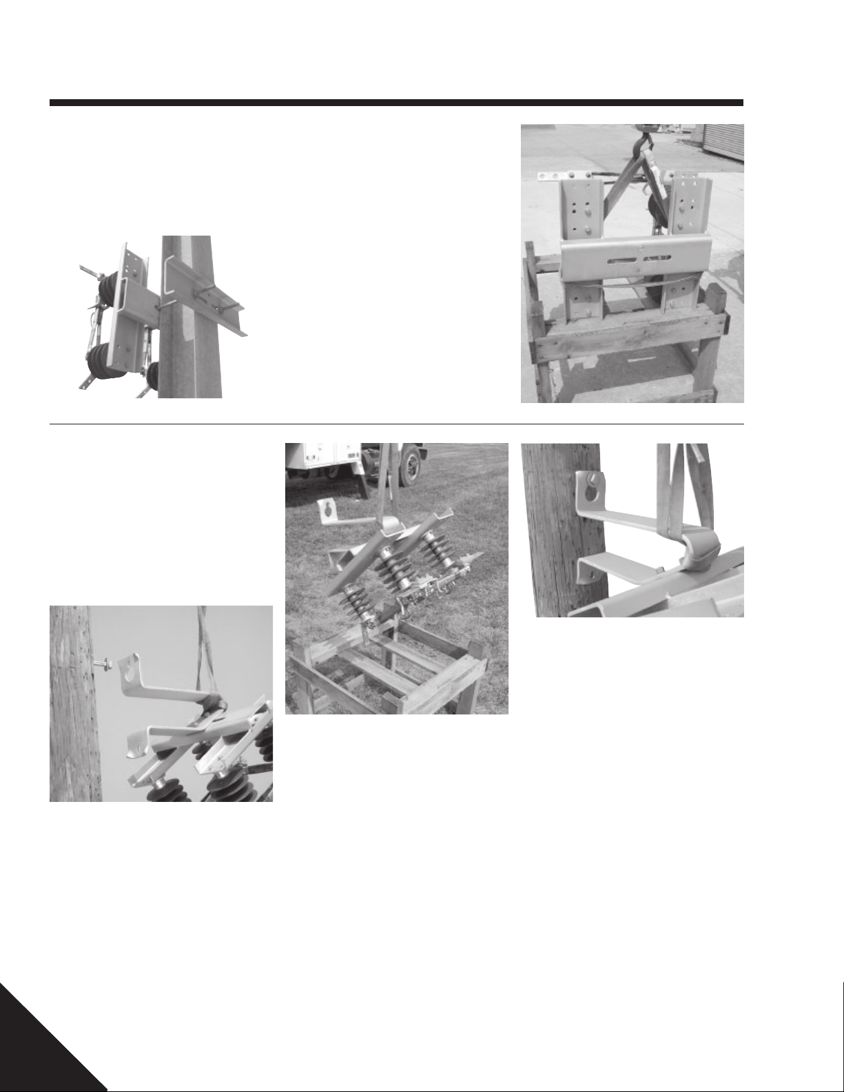
Switch Installation
Back Strap Application
• Refer to Figure 2
• The back strap option is supplied with two
lengths of mounting bolts, 8 inches and
10 inches in length.
Figure 2
Pole Mounting Bracket
Application
• Determine pole mounting bracket location
and drill two 11/16" diameter holes spaced
111/4" apart on the utility pole’s centerline.
• Install one user supplied 5/8" diameter
bolt, washer and nut in the top hole.
• Secure lifting sling as shown
• Using your company’s standard practice,
hoist the switch into position
• Attach the switch using the provided back
strap and appropriate length bolts.
• Adjust the bolts in the switch base and
back strap slots to fit close to the vertical
structure.
•Torque mounting hardware nuts to
60 ft-lb.
• Leave bolt head and washer away from
the pole far enough to hang the mounting
bracket on the bolt.
• If preferred, the mounting bracket may be
installed on the utility pole before the
switch is assembled to the mounting
bracket, or the mounting bracket may be
installed to the switch and then installed
on the utility pole. Torque the two supplied
1
/2" bolts to 60 ft-lb.
• Secure lifting sling as shown
• Using your company’s standard practice,
hoist the switch into position
• Attach the mounting bracket (with or without the switch) to the utility pole,
• Install the lower bolt, washer and nut
(user supplied),
•Torque both user supplied bolts according
to your company standards.
6 of 12
P805-0011 Rev. A
©
2002 Hubbell Power Systems, Inc., 210 North Allen Street, Centralia, MO 65240 U.S.A.
Page 7
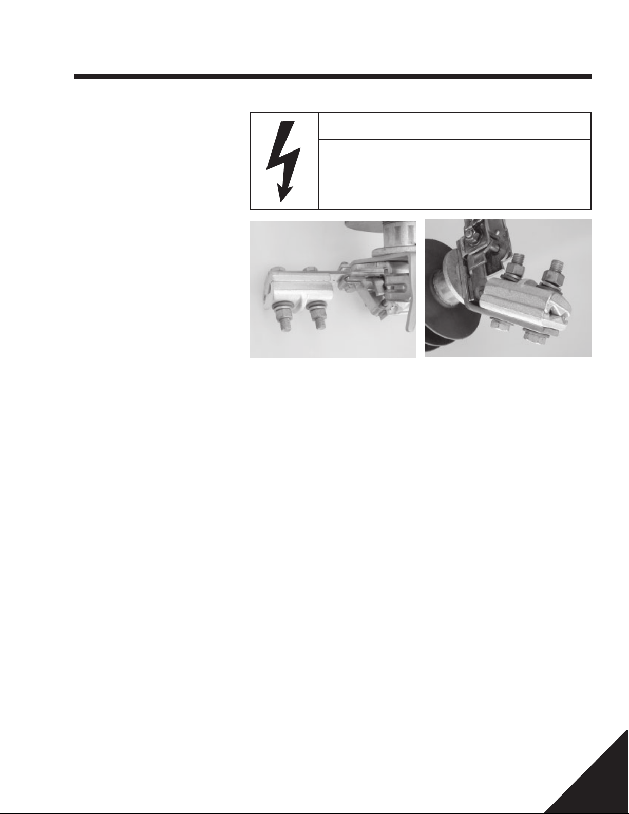
Wiring
Conductors
• Using your company’s standard practices,
train the conductors to the switch terminal
pads
• Use sufficient conductor length to allow
for ease of termination and switch
operation
Connect High Voltage
Conductors
• Wire brush mating surface of the switch
terminal pads and terminal connectors
• Wire brush connector surfaces where
conductors will be secured
• Wire brush conductor surfaces
• Apply a contact sealing paste to the
cleaned surfaces (A.B. Chance Z.L.N. or
equivalent)
• Assemble connectors, conductors and
hardware to the switch terminal pads
• Ensure bolt heads of the terminal
connectors are on the insulator side of the
terminal pad as shown.
•Torque all supplied hardware to 60 ft-lb.
•Torque user supplied hardware according
to your company standards.
CAUTION
High Voltage Electrical Arc Hazard
May cause property damage.
Install terminal connectors with bolt heads toward the insulator.
Failure to do so may compromise the electrical insulation resulting in
an electrical arc.
P805-0011 Rev. A
©
2002 Hubbell Power Systems, Inc., 210 North Allen Street, Centralia, MO 65240 U.S.A.
7 of 12
Page 8
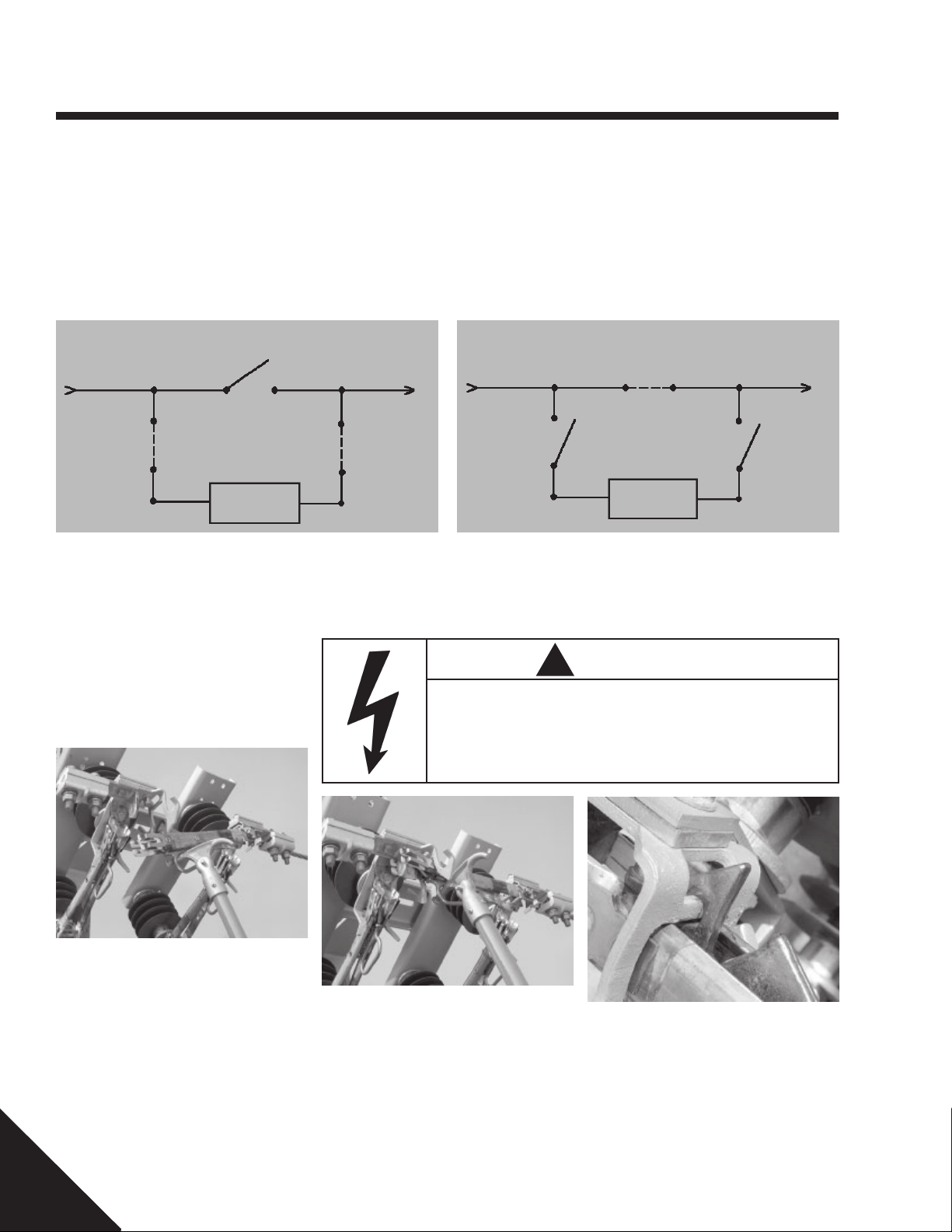
Operation
General
Operation of the BP3 By-Pass switch is
shown in Figures 4 and 5. In normal
operation, the by-pass blade is open and
the two disconnect blades are closed
(Figure 4), allowing the recloser to be in the
circuit. When isolation of the recloser is
required, close the by-pass blade to provide
a parallel current path. Open the disconnect
blades (Figure 5) to isolate the recloser from
the circuit.
•Position yourself below and slightly to the
front of the switch’s hook stick pull ring
•Position feet and body in a manner that
provides good stability and allows for hook
stick use without losing a steady footing
Normal Operating Position
Source Load
Disconnect
Blade
By-Pass
Blade
Recloser
By-Pass Switch
Disconnect
Blade
Recloser
Figure 4
• Under ice conditions, be prepared to use
greater force to overcome the additional
resistance
• Allow a minimum of 24 inches (610 mm)
clearance from the bottom of the hook
stick to the ground for uninterrupted
hookstick travel.
By-Pass Operating Position
Source Load
By-Pass Blade
Recloser
Disconnect
Blade
By-Pass Switch
Disconnect
Blade
Recloser
Figure 5
Closing Switch
•To close the BP3 switch, place a hookstick
in the pull ring on the blade and rotate the
blade to an intermediate position as
shown in Figure 6.
Figure 6
•Turn head and look away from the switch.
• Quickly, firmly and without hesitation
drive the switch to the closed position.
• Carefully remove the hookstick from the
pull ring to avoid opening the switch.
!
WARNING
High Voltage Electric Arc Hazard.
Can cause death, severe personal injury or property damage.
Close the by-pass blade before opening either of the two disconnect
blades. Failure to do so will result in an electrical arc.
• The BP3 switch is properly closed when
the blade hook is fully engaged with the
latch portion of the blade stop as shown in
Figure 7.
Figure 7
— BLADE HOOK
LATCH —
• Visually check each switch blade for
proper latching.
8 of 12
P805-0011 Rev. A
©
2002 Hubbell Power Systems, Inc., 210 North Allen Street, Centralia, MO 65240 U.S.A.
Page 9
Operation
Opening Switch
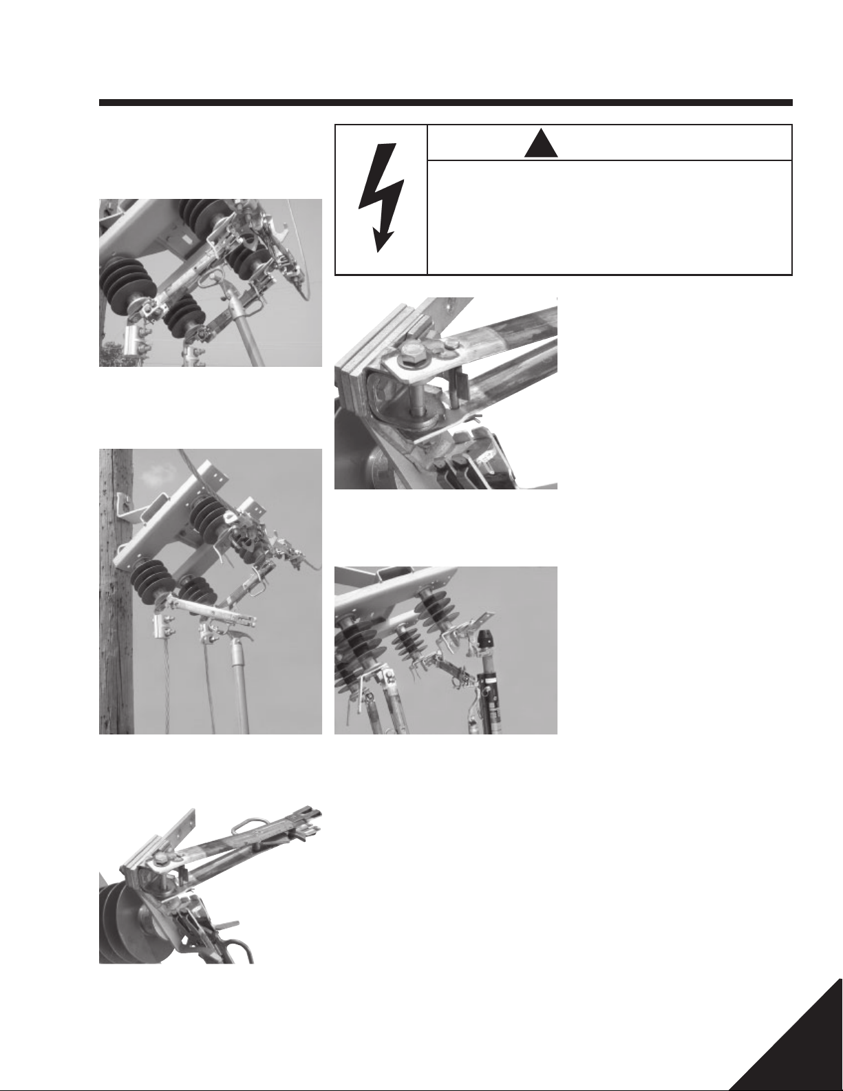
•To open the BP3 switch, place a
hookstick in the pull ring as shown in
Figure 8.
Figure 8
•Turn head and look away from the switch.
• Quickly, firmly and without hesitation
pull down and towards the hinge end of
the switch at about a 45
°
angle.
!
WARNING
High Voltage Electric Arc Hazard.
Opening an energized disconnect switch without a loadbreak tool will
create an electrical arc.
Can cause death, severe personal injury or property damage.
Use appropriately rated loadbreak tool to open a switch that is carrying load current.
• Once the switch is open, complete the
blade travel to its stop position.
• Carefully remove the hookstick from the
pull ring.
• The by-pass blade is equipped with an
open blade latch. Visually check that the
stop pin has engaged the open blade
latch.
• The by-pass blade of the BP3 switch is
also equipped with loadbreak hooks for
use with a loadbreak tool.
•To open the by-pass blade of the switch
under load, use only an approved
loadbreak tool or device designed for use
with switches.
•Follow the instructions provided with such
tools.
P805-0011 Rev. A
©
2002 Hubbell Power Systems, Inc., 210 North Allen Street, Centralia, MO 65240 U.S.A.
9 of 12
Page 10
Operation
• Standard BP3 switches have blade
guides on the left and right disconnect
blades. Open only after by-pass blade
has been closed electrically paralleling
the disconnect blades.
• The loadbreak hook option equips the
disconnect blades with single sided
loadbreak hooks. The loadbreak hooks
allow the use of a loadbreak tool for the
switching of load, capacitor, line/cable
charging and magnetizing currents.
• To open loadbreak hook equipped
disconnect or by-pass blades of an
energized by-pass disconnect switch,
use only an approved loadbreak tool
designed for use with switches.
• Follow the instructions provided with such
tools.
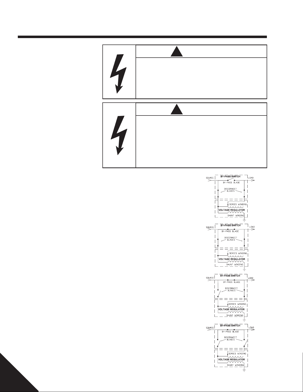
• When by-passing a voltage regulator,
except three-phase induction
regulator, follow the steps outlined
below. For three-phase induction
regulators, contact supervisor or factory
representative.
!
WARNING
High Voltage Electric Arc Hazard.
Opening an energized disconnect switch without a loadbreak tool will
create an electrical arc.
Can cause death, severe personal injury or property damage.
Use appropriately rated loadbreak tool to open an energized by-pass
switch.
!
WARNING
High Voltage Electric Arc Hazard.
By-passing a voltage regulator without first setting the regulator to its
neutral position and without using a loadbreak tool to open the remaining disconnect blade will create an electrical arc.
Can cause death, severe personal injury or property damage.
Set regulator to its neutral position and use appropriately rated
loadbreak tool to open the remaining disconnect blade to by-pass a
voltage regulator.
1. Set voltage regulator automatic control to manual. Set voltage regulator to its neutral position. By-
pass blade is open. Disconnect blades are closed.
2. Close by-pass blade. The by-pass blade shunts the voltage regulator series winding. Disconnect
blades are closed.
3. Open either disconnect blade to disconnect the voltage regulator series winding. By-pass blade is
closed. Voltage regulator shunt winding remains energized through other disconnect blade.
4. Open remaining disconnect blade using loadbreak tool to interrupt the voltage regulator
magnetizing current. By-pass blade is closed. Disconnect blades are open.
5. Reverse the above sequence of steps to return a voltage regulator to service.
10 of 12
P805-0011 Rev. A
©
2002 Hubbell Power Systems, Inc., 210 North Allen Street, Centralia, MO 65240 U.S.A.
Page 11
Maintenance
General
Prolong the life of the BP3 By-Pass switch
with a periodic inspection and maintenance
program. Although the switch is designed for
long-term exposure in all weather conditions, certain environments may reduce its
life without periodic maintenance. Following
these minimum inspection and maintenance
procedures will help ensure long service life.
!
DANGER
Hazardous voltage.
Contact with energized lines will result in death, personal injury or
property damage.
All maintenance work should be performed on de-energized switches. If
work must be performed on live lines, follow your company’s standard
safe operating procedures.
Note: It is recommended that all switches
go through a maintenance check at least
once a year; more frequently if located in
a contaminated area.
For additional recommendations, refer to
ANSI C37.35 “IEEE Guide for the Application, Installation, Operation, And Maintenance of High Voltage Air Disconnect and
Load Interrupter Switches."
!
WARNING
Hazardous voltage.
Can cause death, severe personal injury.
Contact with the switch bases, hardware or crossarm could result in
electrical shock. Ground the switch bases and mounting hardware prior
to maintenance.
Switch
Operate the switch periodically to clean contact surfaces to keep parts moving freely.
• Check for burned or pitted contacts and
replace if necessary. Lubricate if necessary with Optimol® grease C600-2870
• Check the hinge bolts for looseness. If
loose, clean bolt threads, apply Loctite®271 and torque to 40-in-lb.
• Inspect all blade rivets for tightness and
replace blade assembly if loose.
• Inspect the mounting hardware and
tighten according to specifications located
in the Installation Section of the manual.
• Replace any damaged or tracked insulators. Clean or replace if heavily contaminated. Consult your factory representative
for authorized replacement insulators.
Conductors
• Be sure all conductors are routed so they
do not interfere with switch operation
• Inspect all conductors to be sure terminations are tight and corrosion free
• If necessary, clean and apply contact
sealing paste (A.B. Chance Z.L.N. or
equivalent) and retighten terminations.
P805-0011 Rev. A
©
2002 Hubbell Power Systems, Inc., 210 North Allen Street, Centralia, MO 65240 U.S.A.
11 of 12
Page 12

Notes/Records
12 of 12
P805-0011 Rev. A
©
2002 Hubbell Power Systems, Inc., 210 North Allen Street, Centralia, MO 65240 U.S.A.
 Loading...