

Page 1
ASSEMBLY & INSTALLATION INSTRUCTIONS
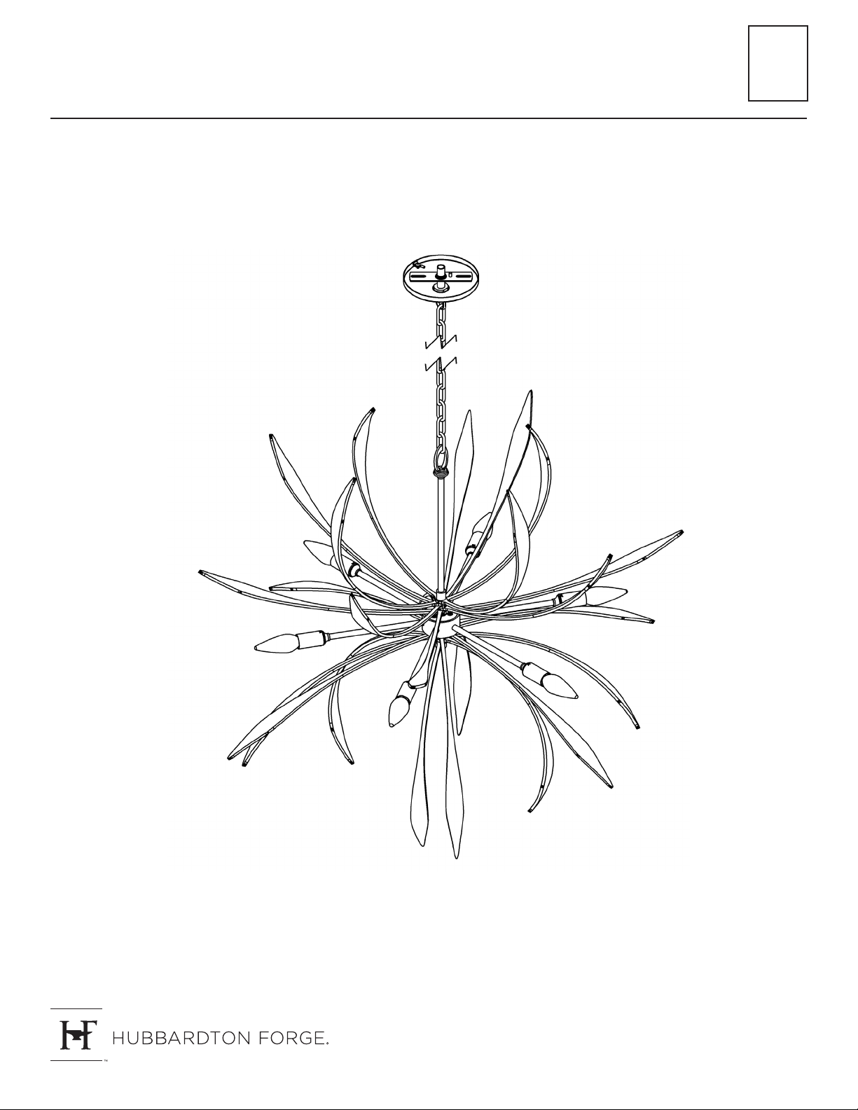
Dahlia Chandelier 104350
A558
© 2021 Hubbardton Forge, LLC. All rights reserved
42270 Rev A
1 OF 4
Page 2

ASSEMBLY & INSTALLATION INSTRUCTIONS
Dahlia Chandelier 104350
Component Parts
A Center Socket Assembly
B Decorative Assembly (2)
C Washer (2)
D Top Stud
E Bottom Stud
F Fixture Coupling
A558
G Fixture Loop
H Cap
I Crossbar
J Lock Nut
K Nipple
L Ground Screw
M Canopy
N Canopy Ring
O Canopy Loop
P Chain
Q Socket
42270 Rev A
2 OF 4
Page 3
ASSEMBLY & INSTALLATION INSTRUCTIONS
Dahlia Chandelier 104350
CAUTION: FAILURE TO INSTALL THIS FIXTURE PROPERLY MAY RESULT IN SERIOUS PERSONAL INJURY
OR DEATH AND PROPERTY DAMAGE. We recommend installation by a licensed electrician. This product must be
installed in accordance with applicable installation code(s), by a person familiar with the construction and operation of
the product and the hazards involved.*
Caution: Do not exceed maximum wattage noted on xture. Use only recommended bulbs with xture.
Please Note: After installation extra hardware and accessories are possible; our kits are used on multiple products.
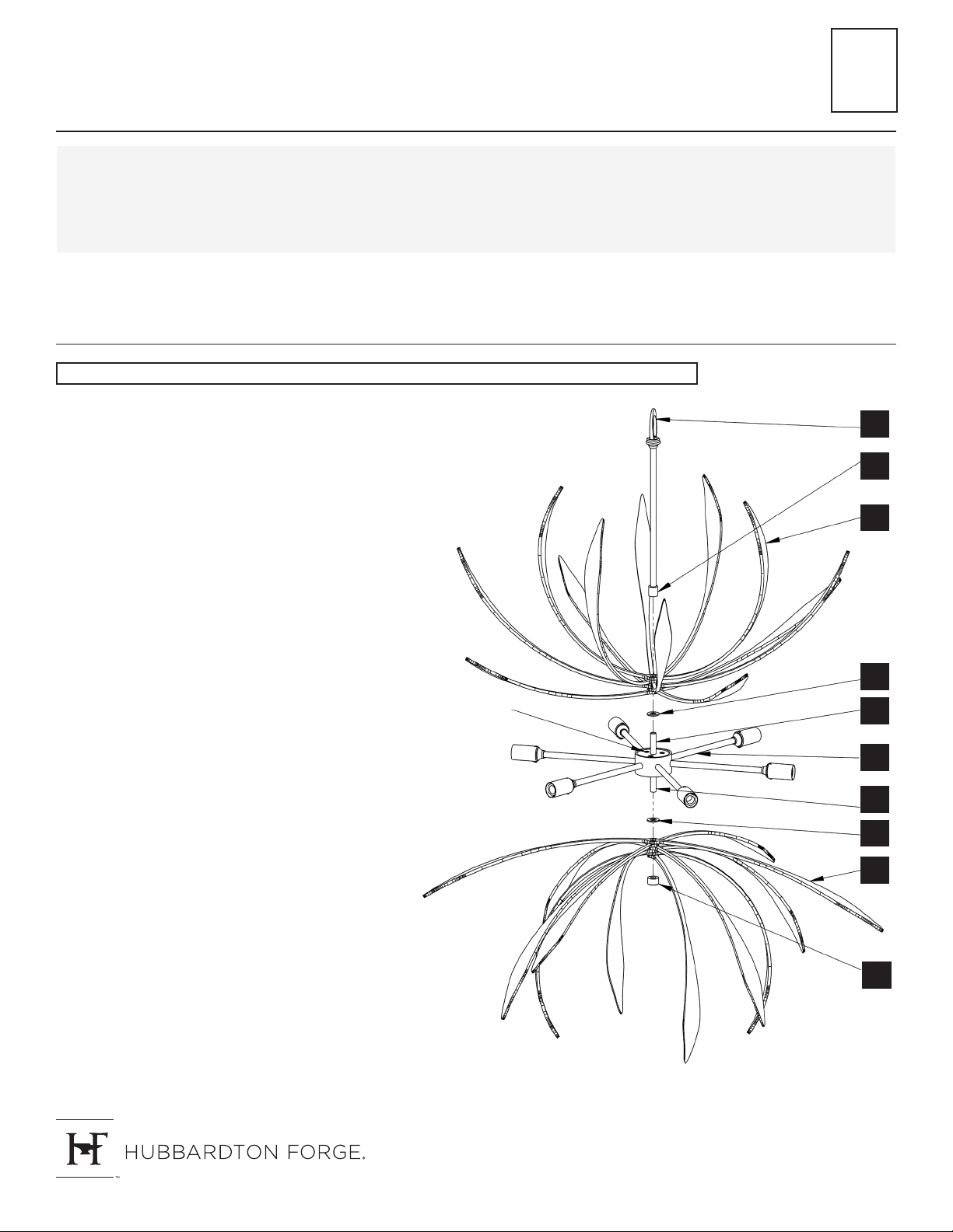
To Assemble Fixture (Figure 1)
CAUTION: BE SURE POWER IS OFF AT THE MAIN BREAKER BOX PRIOR TO INSTALLATION.
A558
1. Carefully unpack xture from the carton.
2. Locate (2) decorative elements (B) and center
socket assembly (A).
3. Locate side of center socket assembly (A) with
wires exiting. This is the top.
4. Install a washer (C), found in kit bag, over wires
and onto top stud (D) followed by decorative
element (B). Refer to Figure (1) for orientation.
5. Slide wires through xture coupling (F) and out
xture loop (G). Apply a drop of the supplied
thread locking compound to the internal threads
of the xture coupling.
Note: Application of the thread locking
compound is necessary to prevent the parts
from loosening during regular maintenance and
cleaning of the fixture. Be certain to apply the
compound.
Thread coupling (F) onto top stud (D) to secure
top decorative assembly (B).
Note: Decorative assembly (B) will still be able
to spin to desired orientation.
6. Cap (H) is shipped installed on bottom stud (E).
Remove and set aside for later step.
TOP
G
F
B
C
D
A
E
C
B
7. Slide remaining washer (C) found in kit bag over
bottom stud (E) followed by remaining decorative
assembly (B).
8. Secure with cap (H).
Note: Decorative assembly (B) will still be able
to spin to desired orientation.
9. Follow steps on next page to install xture.
H
(Figure 1)
42270 Rev A
3 OF 4
Page 4
ASSEMBLY & INSTALLATION INSTRUCTIONS
Dahlia Chandelier 104350
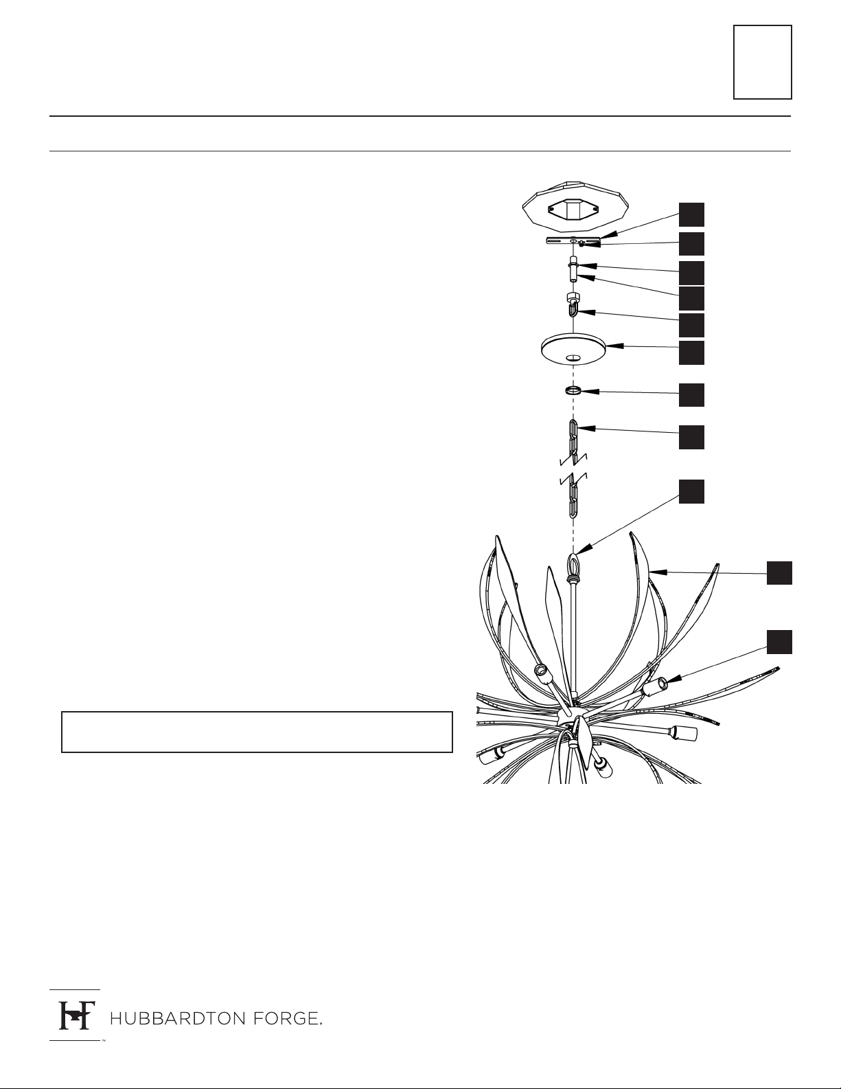
To Install Fixture (Figure 2)
1. Using two machine screws (not provided), fasten the crossbar (I)
to the electric box with the head of the ground screw (L) facing
down.
Note: A new electric box comes with screws. When replacing a
fixture, retain the existing screws for use with the new fixture.
2. Thread nipple (K) into crossbar (I) and then thread lock nut (J)
and canopy loop (O) onto threaded nipple, leaving parts loose.
Adjust the length of threaded nipple in crossbar so that canopy
ring (N), which comes threaded onto canopy loop, will hold
canopy (M) against the ceiling with no threads showing for best
appearance. When the correct adjustment is established, tighten
lock nut against crossbar to hold adjustment.
A558
I
L
J
K
O
M
3. Remove the crossbar (I) assembly from electrical box.
4. Attach one end of the chain (P) to the xture loop (G) using a
chain spreader (not provided). Lace the wires through every other
link of the chain to the end. Slip wires and chain through canopy
ring (N), and canopy (M). Allow canopy ring and canopy to slide
down chain and rest on xture loop. Fasten the chain to the
canopy loop.
5. Slip wires through the canopy loop (O) and nipple (K). Make sure
to provide enough slack in the wire to ensure weight of xture is
supported by the chain (P).
6. Using two machine screws (not provided), reattach the crossbar
(I) to the electric box.
7. Using suitable wire connectors (not provided) connect xture
wires to supply wires (white to ribbed side of the xture cord,
black to smooth side). Run a pigtail lead from crossbar ground
screw (L) to the junction box and connect all ground wires (bare
copper or green to bare copper or green).
CAUTION: MAKE SURE WIRE CONNECTORS ARE TWISTED ON
SECURELY AND NO BARE WIRE IS EXPOSED.
8. Raise canopy (M) to the ceiling and secure loop collar (N) to
canopy loop (O).
N
P
G
B
Q
9. Install bulbs (not provided) into sockets (Q).
(Figure 2)
10. Restore electricity at main breaker.
If you need further assistance, or nd that you are missing any parts, please contact the dealer from which you
purchased this product. We hope you enjoy your xture!
* Hubbardton Forge will not be liable for injury or damage caused by improper installation, lamping or use of
this xture.
42270 Rev A
4 OF 4
 Loading...