

Page 1
Installation Instructions B275
CAUTION: FAILURE TO INSTALL THIS FIXTURE PROPERLY MAY RESULT IN SERIOUS PERSONAL
INJURY OR DEATH AND PROPERTY DAMAGE. We recommend installation by a licensed electrician.
This product must be installed in accordance with applicable installation code(s), by a person familiar with the
construction and operation of the product and the hazards involved.*
Caution: Do not exceed maximum wattage noted on fixture. Use only recommended bulbs with fixture.
(Figure 2)
(Figure 1)
Outdoor Sconces 30-5650 & 30-5655 Page 1 of 2
Please Note: This fixture is designed to be mounted on a standard wall surface and may not be suitable for all
applications. If installing in a non-wood frame application, we recommend consulting a qualified builder or electrician.
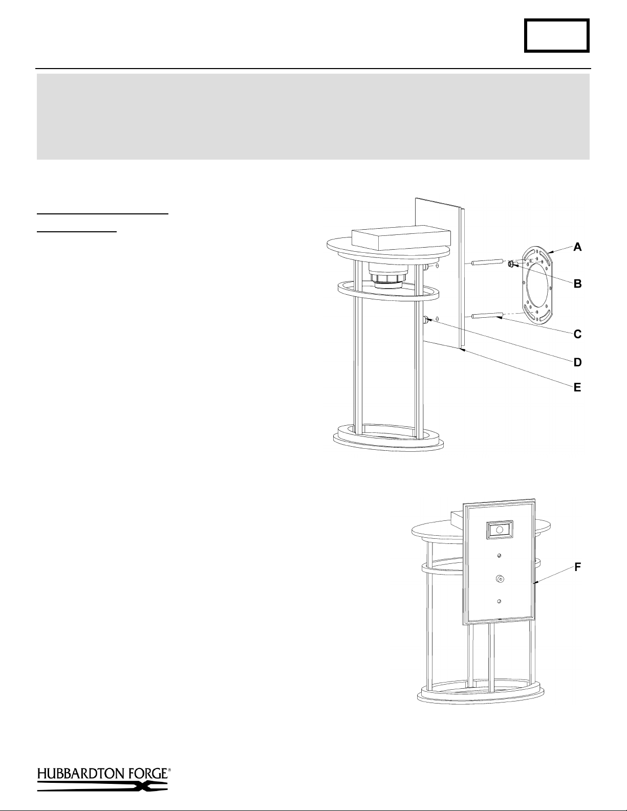
To Mount Fixture to Wall (Figures 1 & 2)
Component Parts
A Crossbar
B Ground Screw
C Threaded Stud (2)
D Knurled Ball (2)
E Fixture Assembly
F Caulking Lip
Caution: Be sure power is off at the main breaker box
prior to installation.
1. Carefully unpack the fixture from the carton.
2. Using two machine screws (not provided) attach
crossbar (A) to the electric box making sure crossbar
is level.
Note: A new electric box comes with screws. When
replacing a fixture, retain the screws for use with the
new fixture.
3. Start threaded studs (C) into appropriate holes in
crossbar (A). Adjust the threaded studs (C) to proper length
to ensure the fixture (E) will fit snugly to the wall.
4. Run a pigtail lead from crossbar ground screw (B) to the
junction box.
5. Hold the fixture assembly (E) close to the wall mount bracket and
using suitable wire connectors (not provided), connect fixture wires
to supply wires (white to white or ribbed and black to black or
smooth). Connect all ground wires (bare copper or green to bare
copper or green).
Caution: Make sure wire connectors are twisted on securely, and
no bare wires are exposed.
6. Apply a generous bead of a suitable caulking material to caulk lip
(F) on the fixture (not provided). Caulk should be applied around
the entire perimeter of the back plate.
7. Carefully tuck all wires behind the fixture. Place fixture (E) over
threaded studs (C) and tighten firmly to mounting surface using
barrel knobs (D).
Hand-Forged, Vermont-Made Lighting and Accessories
154 Route 30 South, Castleton, Vermont 05735 27844B
(continued)
Page 2
Installation Instructions B275
(Figure 3)
Outdoor Sconces 30-5650 & 30-5655 Page 2 of 2
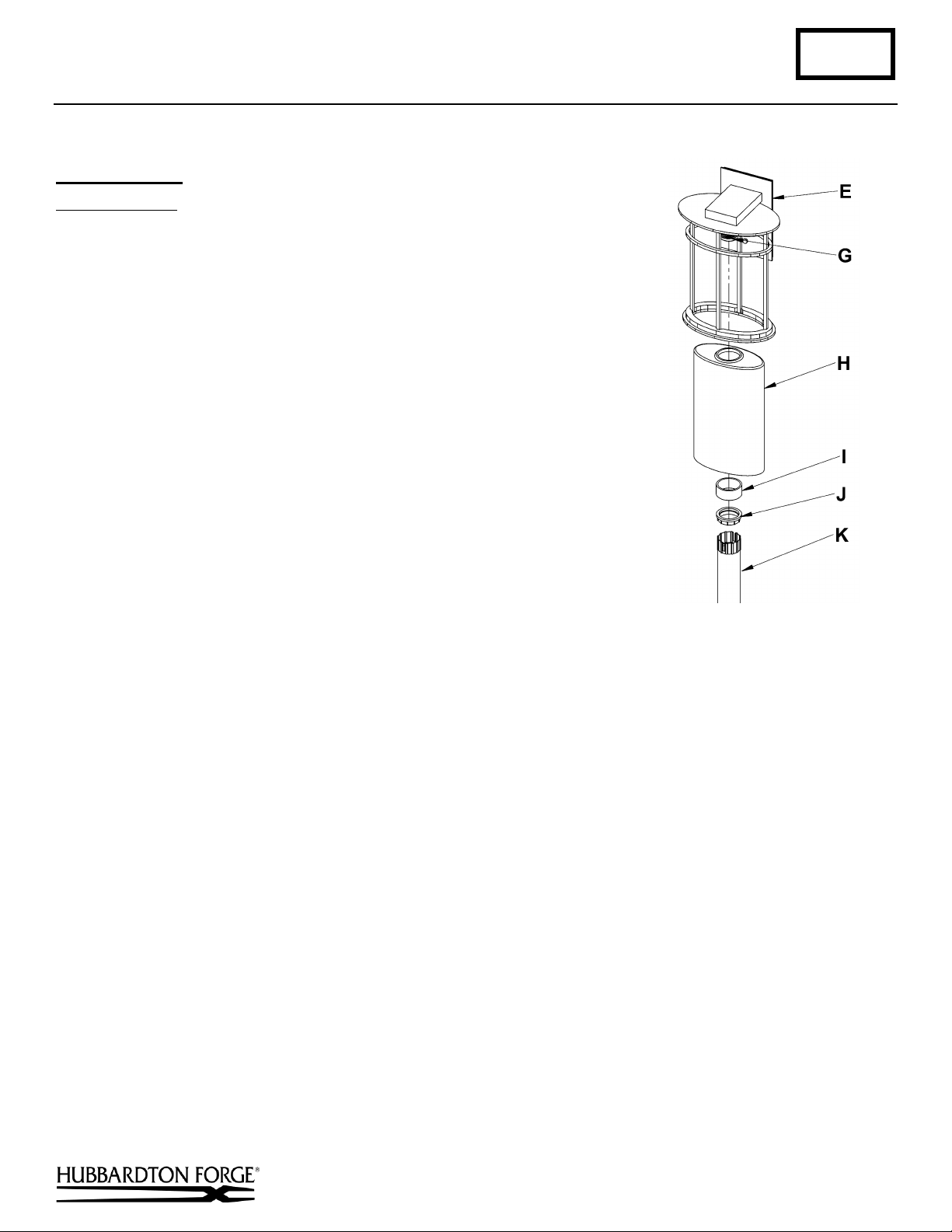
To Install Glass (Figure 3)
Component Parts
E Fixture Assembly
G Socket
H Glass
I Aluminum Spacer
J Retaining Ring
K Retaining Ring Tool
1. Remove retaining ring (J) and spacer (I) from socket (G). Retaining ring and
spacer ships installed.
2. Slip glass (H) over socket (G).
3. Slide spacer (I) over socket (G) followed by retaining ring (J).
4. Thread retaining ring (J) onto socket (G) using retaining ring tool (K) provided
until it is snug against the fixture assembly (E). Do not over tighten.
5. Install bulb. Not Included.
If you need further assistance, or find that you are missing any parts, please contact the dealer from which you purchased
this product. We hope you enjoy your fixture!
* Hubbardton Forge will not be liable for injury or damage caused by improper installation, lamping or use of this fixture.
Hand-Forged, Vermont-Made Lighting and Accessories
154 Route 30 South, Castleton, Vermont 05735 27844B
 Loading...