

Page 1

Installation Instructions B235
p
Mobius Sconce 28-9450 Page 1 of 6
CAUTION: FAILURE TO INSTALL THIS PRODUCT PROPERLY MAY RESULT IN PERSONAL INJURY
OR PROPERTY DAMAGE. We recommend installation by a qualified individual trained in the building trade.
This product must be installed in accordance with applicable installation code(s), by a person familiar with the
construction and o
Please Note: This fixture is designed to be mounted on a standard wall surface and may not be suitable for all
applications. If installing in a non-wood frame application, we recommend consulting a qualified builder or electrician.
eration of the product and the hazards involved.*
To Install to Wall
Component Parts
A Fixture Pipe
B Knurled Screw
C Locking Collar
D Mounting Arm (2)
E Set Screw (2)
F Wall Mount Plate (2)
G #10 Screws (2)
H Cord
1. Carefully unpack the fixture from the carton.
2. Slide locking collar (C), O-ring, and mounting
arms (D) onto the fixture pipe (A).
Note: O-ring can easily slide though mounting
arm (D) prior to installation. O-ring might
need to be adjusted to proper location;
between locking collar (C) and mounting arm
(D).
3. Remove wall mount plate (F) from the
mounting arm (D) by loosening set screw (E)
and sliding wall mount plate (F) from
mounting arm (D). Do this for both arms.
4. Hold the fixture in position level and plumb
against the wall and mark the location of the
mounting holes. Set fixture aside.
5. Attach wall mount plates (F) to the wall using
silver #10 screws (G). Be careful not to over
tighten the screws.
6. Slide the mounting arms (D) onto the wall
mount plates (F) and secure with set
screws (E).
7. Tighten knurled head screw (B) in locking
collar (C) to secure the fixture pipe (A).
8. Plug the fixture’s cord (H) into the supplied
touch dimmer module, and plug the touch
dimmer module into the wall.
9. Use steps below to install bulb and shade.
Hand-Forged, Vermont-Made Lighting and Accessories
154 Route 30 South, Castleton, Vermont 05735
26937 Rev A
(Figure 1)
(continued)
Page 2

Installation Instructions B235
Mobius Sconce 28-9450 Page 2 of 6
To Assemble Flat Shades
Component Parts:
I Flat Shade Panel (2)
J Male End Plastic Button (8)
K Female End Plastic Button (8)
Step 1 Identify all parts needed.
(K) Female End Plastic
Buttons (8)
(J) Male End Plastic
Buttons (8)
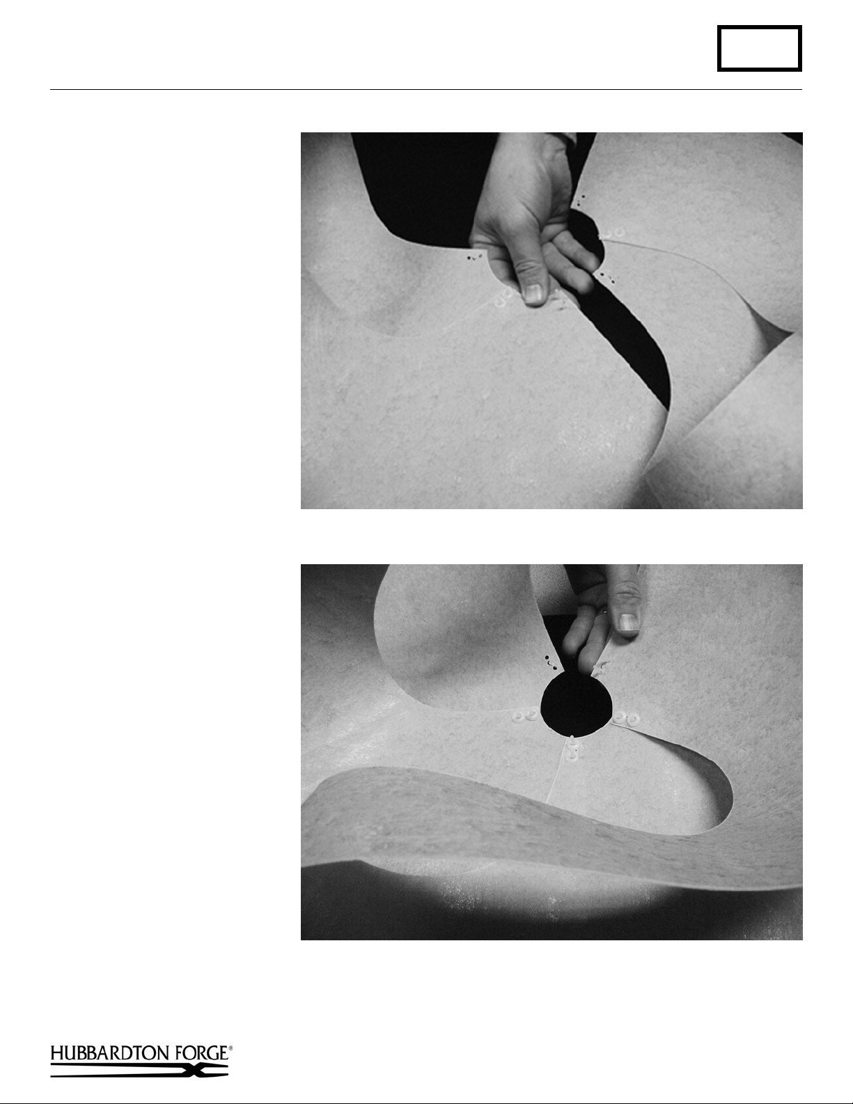
Step 2 Fold shade panel (I) over and
align letter designations “L”.
Note: Top letter "L" should be
oriented the same as the bottom
letter "L".
Step 3 Slip male end of plastic button
down through bottom of shade
panel as shown.
(I) Flat Shade Panel (2)
(continued)
Hand-Forged, Vermont-Made Lighting and Accessories
154 Route 30 South, Castleton, Vermont 05735
26937 Rev A
Page 3

Installation Instructions B235
Mobius Sconce 28-9450 Page 3 of 6
Step 4 Align "L" holes and mount
the other side of the shade
panel (I) onto the two male
end plastic buttons (J). Install
two female end plastic buttons
(K) and press firmly to snap
into place. Clip excess length
of the male button off after
installing female plastic
buttons.
Step 5 Repeat steps 2-4 for other flat
shade panel (I).
Hand-Forged, Vermont-Made Lighting and Accessories
154 Route 30 South, Castleton, Vermont 05735
26937 Rev A
(continued)
Page 4
Installation Instructions B235
Mobius Sconce 28-9450 Page 4 of 6
Step 6 Slip male end plastic buttons
(J) through the “C” side of the
shade panel (I).
“C” should read the same as
shown).
mount the other side of the
shade panel (I) onto the two
male end plastic buttons (J).
Step 7 Install two female end plastic
buttons (K) and press firmly
to snap into place. Clip excess
length of the male button off
after installing female plastic
buttons.
Step 8 Fold the shade panel (I) as
shown to match the “C” sides.
Insert the other side of the
shade panel (I) onto the two
male end plastic buttons (J).
Align "C" holes and
Note: Letter
Hand-Forged, Vermont-Made Lighting and Accessories
154 Route 30 South, Castleton, Vermont 05735
26937 Rev A
(continued)
Page 5

Installation Instructions B235
Mobius Sconce 28-9450 Page 5 of 6
Step 9 Install two female end plastic
buttons (K) and press firmly
to snap into place. Clip excess
length of the male button off
after installing female plastic
buttons.
Bottom View of Assembled Shade
Hand-Forged, Vermont-Made Lighting and Accessories
154 Route 30 South, Castleton, Vermont 05735
26937 Rev A
(continued)
Page 6

Installation Instructions B235
Mobius Sconce 28-9450 Page 6 of 6
To Install Flat Shade Option
Component Parts
L Socket
M Shade Assembly
N Forged Bar/Plate Assembly
O Retaining Ring
1. Slip shade assembly (M) followed by forged bar/plate assembly (N)
over socket (L).
2. Thread retaining ring (O) onto socket (L) and tighten until snug.
3. Install light bulb (not included).
4. Restore electricity at the main breaker.
(Figure 2)
To Install Conic Shade Option
Component Parts
L Socket
N Forged Bar/Plate Assembly (Optional)
O Retaining Ring
P Shade
(Figure 3)
1. Slip shade (P) followed by optional forged bar/plate assembly (N) over
socket (L).
2. Thread retaining ring (O) onto socket (L) and tighten until snug.
3. Install light bulb (not included).
4. Restore electricity at the main breaker.
(Figure 2)
(Figure 3)
If you need further assistance, or find that you are missing any parts, please contact the dealer from which you purchased
this product. We hope you enjoy your fixture!
* Hubbardton Forge will not be liable for injury or damage caused by improper installation, lamping or use of this fixture.
Hand-Forged, Vermont-Made Lighting and Accessories
154 Route 30 South, Castleton, Vermont 05735
26937 Rev A
 Loading...