

Page 1
Assembly Instructions C35
(Figure 3)
(Figure 1)
(Figure 2)
Mobius Floor Lamp 23-4505 & 23-4505C Page 1 of 7
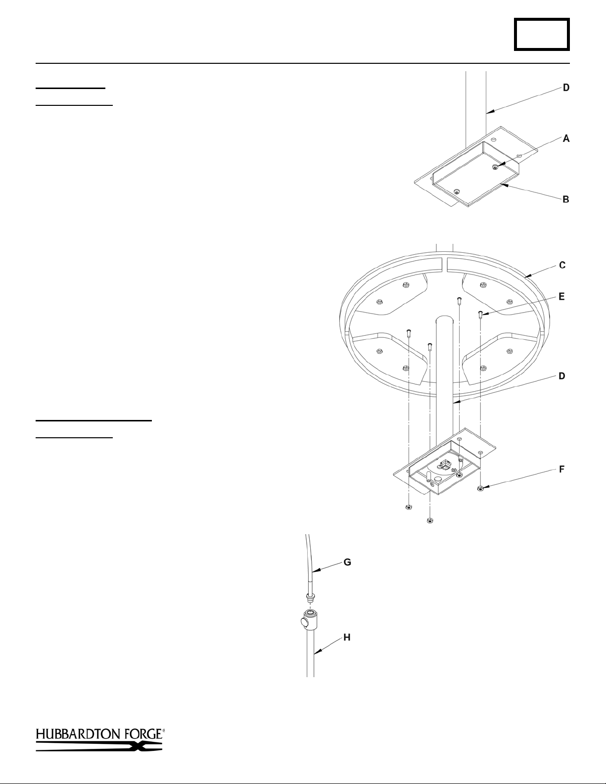
Prepare Base (Figures 1& 2)
Component Parts
A 8-32 Screw (2)
B Wireway Cover Plate
C Base
D Lower Pipe Assembly
E Threaded Stud (4)
F Hex Nut (4)
1. Carefully unpack the lamp from the carton. The lamp has been
packaged with the cord routed through the various
parts of the lamp. Take care not to damage the cord
when removing the lamp from the packaging.
2. Remove two 8-32 screws (A) holding wireway
cover plate (B) to fixture. Set all parts to the side
for later use.
3. Slip base (C) over lower pipe assembly (D)
allowing the four threaded studs (E) to slip thru the
four holes in the lower pipe assembly (D).
4. Install four hex nuts (F) onto threaded stud (E) and
tighten.
Assemble Mid-Section (Figure 3)
Component Parts
G Arm Assembly
H Tube Assembly
1. Thread arm assembly (G) to tube assembly (H), be
certain not to twist th e co rd .
Hand-Forged, Vermont-Made Lighting and Accessories
154 Route 30 South, Castleton, Vermont
24809 Rev C
(continued)
Page 2
Assembly Instructions C35
(Figure 5)
(Figure 4)
Mobius Floor Lamp 23-4505 & 23-4505C Page 2 of 7
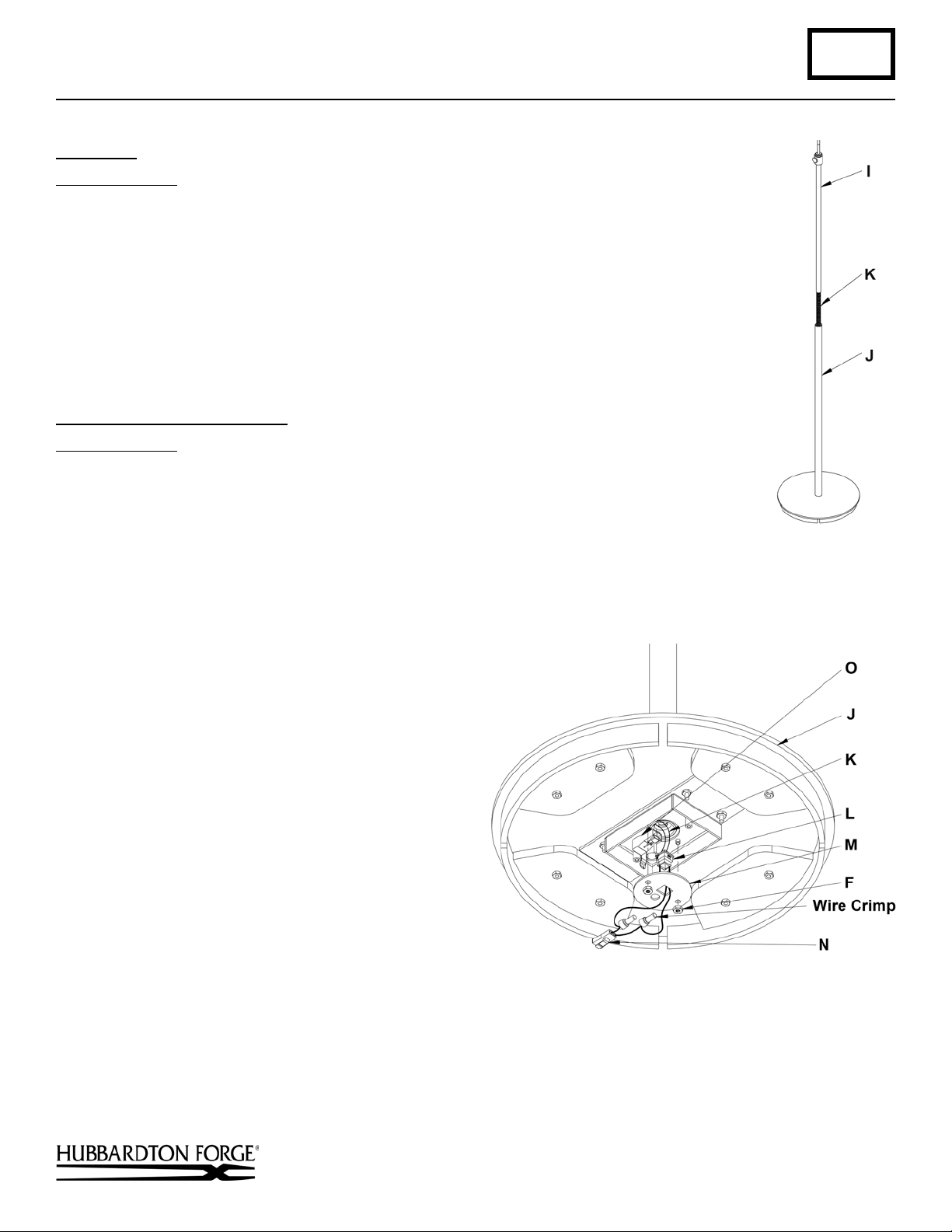
Assemble (Figure 4)
Component Parts
I Upper Assembly
J Base Assembly
K Coiled wire
1. Slip upper assembly (I) into base assembly (J).
2. Lower upper assembly (I) as far into the base assembly (J) so the coiled wire (K)
with the connector comes out into the wireway area in the base.
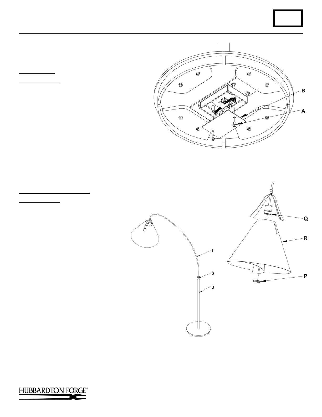
Complete Wiring in the Base (Figures 5 & 6)
Component Parts
A 8-32 Screw (2)
B Wireway Cover Plate
F Hex Nut (2)
J Base Assembly
K Coiled wire
L Strain Relief
M Cover Plate
N Male Quick Connect
O Female Quick Connect
1. Remove cover plate (M) by loosening and
removing two hex nuts (F) from base assembly (J).
Save for later use.
2. Pull coiled wire (K) with male quick connect (N)
and two wire crimps from the center of the fixture
and push through the cover plate (M).
3. Snap strain relief (L) into cover plate (M).
4. Replace cover plate (M) and the two hex nuts (F).
Tighten hex nuts until snug.
5. Plug the male quick connect (N) into the female
quick connect (O).
6. Replace the wireway cover plate (M) and the two
8-32 screws (A) (Figure 6, next page).
(continued)
Hand-Forged, Vermont-Made Lighting and Accessories
154 Route 30 South, Castleton, Vermont
24809 Rev C
Page 3
Assembly Instructions C35
(Figure 6)
(Figure 7)
(Figure 8)
Mobius Floor Lamp 23-4505 & 23-4505C Page 3 of 7
Install Shade (Figure 7)
Component Parts
P Retaining Ring
Q Socket
R Shade As s embly
1. Refer to instructions beginning on next page to
assemble shade.
2. Remove retaining ring (P) from socket (Q).
Retaining ring is shipped installed.
3. Slip shade assembly (R) over socket (Q).
4. Thread retaining ring (P) onto socket (Q).
5. Install light bulb. (“C” version bulb is included)
To Raise and Spin Fixture (Figure 8)
Component Parts
I Upper Assembly
J Base Assembly
S Thumb Screw
1. Loosen thumb screw (S) and holding
onto the base assembly (J) raise the
upper assembly to desired height.
The upper assembly will also spin at
this point. Note: There is an internal
stop inside the base assembly to
prevent the upper assembly from
turning repeatedly.
2. Once height and location is
determined tighten thumb screw (S)
and set screw below it.
Hand-Forged, Vermont-Made Lighting and Accessories
154 Route 30 South, Castleton, Vermont
24809 Rev C
(continued)
Page 4

Page 5

Assembly Instructions C35
Mobius Floor Lamp 23-4505 & 23-4505C Page 5 of 7
Step 2 Fold shade panel over and align the
letter designations “C”.
Note: Top letter "C" should be
oriented the same as bottom
letter "C".
Step 3 Slip bracket with studs (S) through
the “C” side of the shade panel (R).
Shade panel should appear like this.
Hand-Forged, Vermont-Made Lighting and Accessories
154 Route 30 South, Castleton, Vermont
(continued)
24809 Rev C
Page 6

Assembly Instructions C35
Mobius Floor Lamp 23-4505 & 23-4505C Page 6 of 7
Step 4 Flip shade panel (R) over and
install shade spider (Q) onto the
two studs.
Step 5 Install knobs (T) onto the two
studs.
Step 6 Match the two “L” sides tog ether.
(continued)
Hand-Forged, Vermont-Made Lighting and Accessories
154 Route 30 South, Castleton, Vermont
24809 Rev C
Page 7

Assembly Instructions C35
Mobius Floor Lamp 23-4505 & 23-4505C Page 7 of 7
Step 7 Fold the shade panel (r) with the bracket (S) and
studs towards the shade spider (Q) and push the
studs through the holes in the shade panel (R) and
out through the spider (Q) on the inside.
Step 8 Install knobs (T).
Complete assembled shade.
If you need further assistance, or find that you are
missing any parts, please contact the dealer from which
you purchased this product. We hope you enjoy your
fixture!
* Hubbardton Forge will not be liable for injury or damage
caused by improper installation, lamping or use of this
fixture.
Hand-Forged, Vermont-Made Lighting and Accessories
154 Route 30 South, Castleton, Vermont
24809 Rev C
 Loading...