

Page 1
Assembly & Installation Instructions B156
g
For Ono Sconce 21-7740F Page 1 of 3
CAUTION: FAILURE TO INSTALL THIS FIXTURE PROPERLY MAY RESULT IN SERIOUS PERSONAL
INJURY OR DEATH AND PROPERTY DAMAGE. We recommend installation by a licensed electrician.
This product must be installed in accordance with applicable installation code(s), by a person familiar with the
construction and operation of the product and the hazards involved.*
Caution: Do not exceed maximum watta
Please Note: This fixture is designed to be mounted on a standard wall surface and may not be suitable for all
applications. If installing in a non-wood frame application, we recommend consulting a qualified builder or electrician.
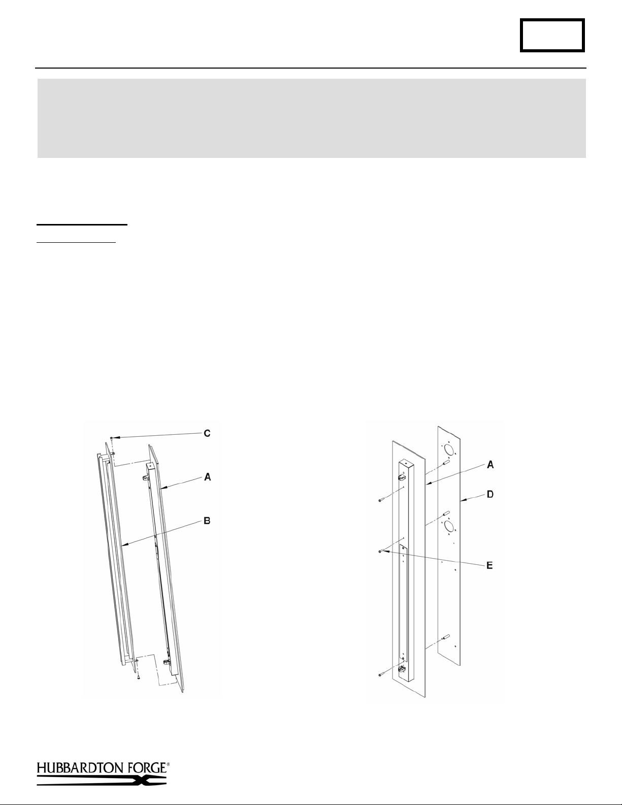
Prepare to Install (Figures 1 & 2)
Component Parts
A Fixture
B Fixture Front
C 8-32 x 3/8” Black Screws (2)
D Wall Mounting Bracket
E 8-32 x 1 ¼” Screws (3)
Caution: Be sure power is off at the main breaker box prior to installation.
1. Carefully unpack the fixture from the carton.
2. Remove two screws (C) (top and bottom) holding fixture front (B) to fixture (A).
3. Place fixture front (B) and screws (C) somewhere safe for later use.
4. Remove three screws (E) from front of fixture (A) to release wall mounting bracket (D).
e noted on fixture. Use only recommended bulbs with fixture.
(Figure 1) (Figure 2)
Hand-Forged, Vermont-Made Lighting and Accessories
P.O. Box 827, 154 Route 30 South, Castleton, Vermont 05735
(continued)
21357
Page 2
Assembly & Installation Instructions B156
For Ono Sconce 21-7740F Page 2 of 3
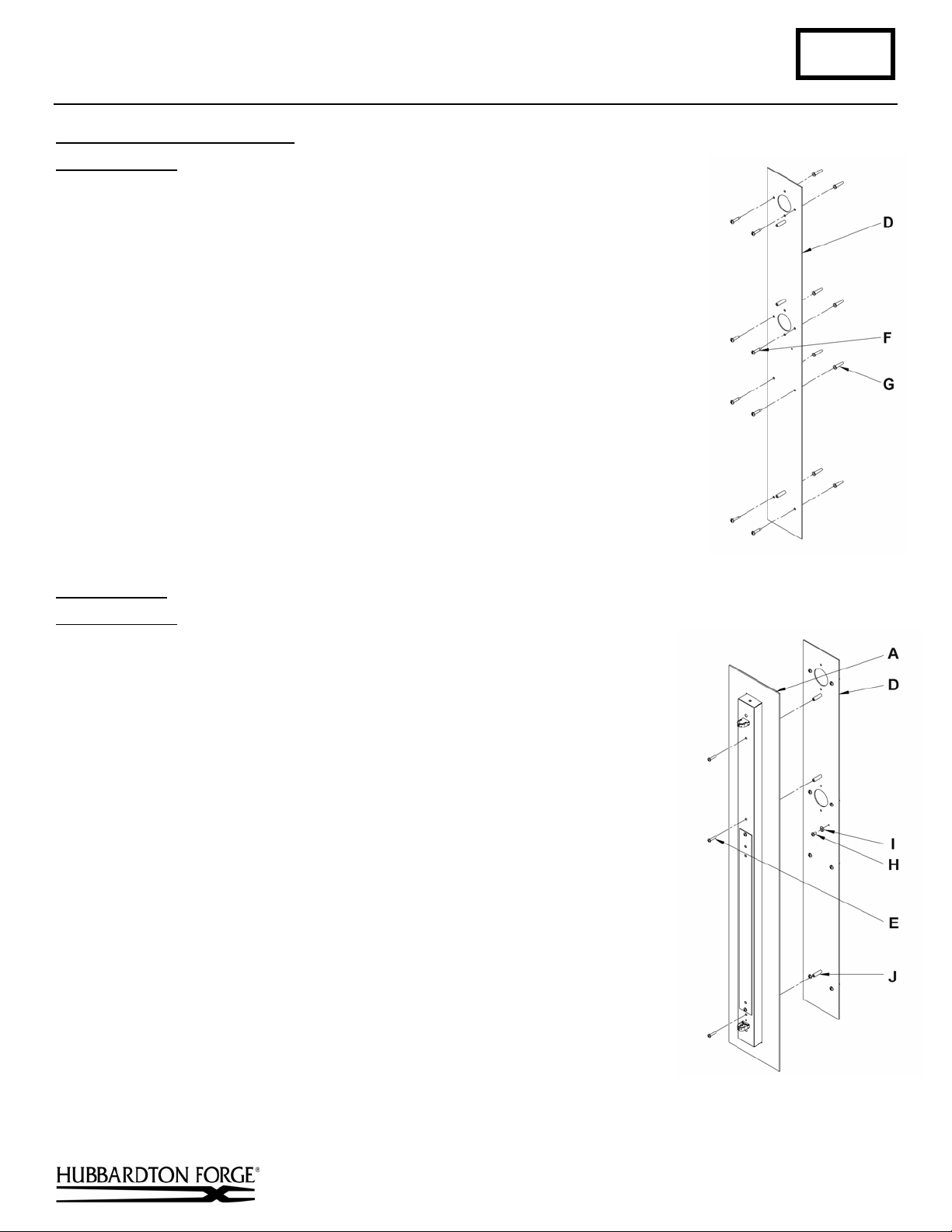
Install Wall Mounting Bracket
Component Parts
D Wall Mounting Bracket
F Anchors (8)
G #10 Screws (8)
1. Place the wall mounting bracket (D) over the electrical box using the center hole
provided, being sure to hold it plum and level. With a pencil, mark the location of
all mounting holes in the wall mount bracket on the wall behind.
IMPORTANT: Wall mounting bracket must be secured to a solid framing member
in at least four locations. Do not depend on drywall anchors alone to support this
fixture. If in doubt, contact a qualified electrician.
Set aside the wall mounting bracket and drill 1/4" holes in the center locations
marked on the wall. For holes using anchors, place the tapered end of the anchors
(F) into the holes and gently tap them flush to the wall using a lightweight
hammer.
2. Thread the wires in the electrical box through the hole in the wall mounting
bracket (D) while moving the bracket into position. Using the 1" #10 screws (G),
screw the bracket securely to the wall. Be careful not to over-tighten or strip the
anchors.
Install Fixture
(Figure 4)
(Figure 3)
(Figure 3)
Component Parts
A Fixture
D Wall Mounting Bracket
E 8-32 x 1-1/4" Screws (3)
H Ground Screw
I Cupped Washer
J Threaded Standoff (3)
1. Hold the fixture (A) close to the wall mounting bracket (D) and using
suitable wire connectors (not provided) connect fixture wires to supply wires
(white to white, black to black, and bare copper or green to bare copper or
green). Ground the mounting bracket using the green ground screw (H) and
cupped washer (I) to secure a pigtail lead to the bracket.
Caution: Make sure wire connectors are twisted on securely, and no bare
wires are exposed.
2. Carefully tuck all wires behind the fixture (A) and inside the wall mounting
bracket (D) and place the fixture over the bracket so the holes in the top and
bottom match the threaded standoffs (J) protruding from the wall mounting
bracket (D). Secure the fixture by threading the 8-32 x 1-1/4" screws (E)
through the holes in the fixture (A) and into the wall mounting bracket (D).
3. See instructions below to install acrylic and fixture front.
(Figure 4)
Hand-Forged, Vermont-Made Lighting and Accessories
P.O. Box 827, 154 Route 30 South, Castleton, Vermont 05735
(continued)
21357
Page 3

Assembly & Installation Instructions B156
For Ono Sconce 21-7740F Page 3 of 3
Install Acrylic
(Figure 5)
Component Parts
B Fixture Front
C 8-32 x 3/8” Black Screws (2)
K Acrylic
L Standoff (2)
M Button Head Screw (2)
1. Place fixture front (B) on flat surface with the back facing up.
2. Slide acrylic (K) through opening in fixture front (B) so it rests on the vertical
bars.
3. Slip standoff (L) inside acrylic (K) and align with hole through the back of the
fixture front (B).
4. Install screw (C) through back of fixture front (B) and thread into standoff (L)
until snug.
5. Repeat step 4 for the other end of acrylic.
6. Align acrylic (K) holes so they match with the two standoffs (L).
7. Install button head screw (M) through acrylic and thread into standoff (L).
8. Tighten button head screws until snug. Be careful not to over tighten.
Install Fixture Front
(Figure 6)
(Figure 5)
Component Parts
A Fixture
B Fixture Front
C 8-32 x 3/8” Black Screws (2)
1. Install fixture front (B) on fixture (A).
2. Install two machine screws (C) top and bottom and tighten.
If you need further assistance, or find that you are missing any parts, please contact
the dealer from which you purchased this product. We hope you enjoy your fixture!
*
Hubbardton Forge will not be liable for injury or damage caused by improper
installation, lamping or use of this fixture.
(Figure 6)
Hand-Forged, Vermont-Made Lighting and Accessories
P.O. Box 827, 154 Route 30 South, Castleton, Vermont 05735
21357
 Loading...