

Page 1
Assembly & Installation Instructions B117
g
For 20-7858 After Hours Wall Sconce Page 1 of 2
CAUTION: FAILURE TO INSTALL THIS FIXTURE PROPERLY MAY RESULT IN SERIOUS PERSONAL
INJURY OR DEATH AND PROPERTY DAMAGE. We recommend installation by a licensed electrician.
This product must be installed in accordance with applicable installation code(s), by a person familiar with the
construction and operation of the product and the hazards involved.*
Caution: Do not exceed maximum watta
For fixtures requiring assembly, please refer to assembly instructions before installation.
Please Note: This fixture is designed to be mounted on a standard wall surface and may not be suitable for all
applications. If installing in a non-wood frame application, we recommend consulting a qualified builder or electrician.
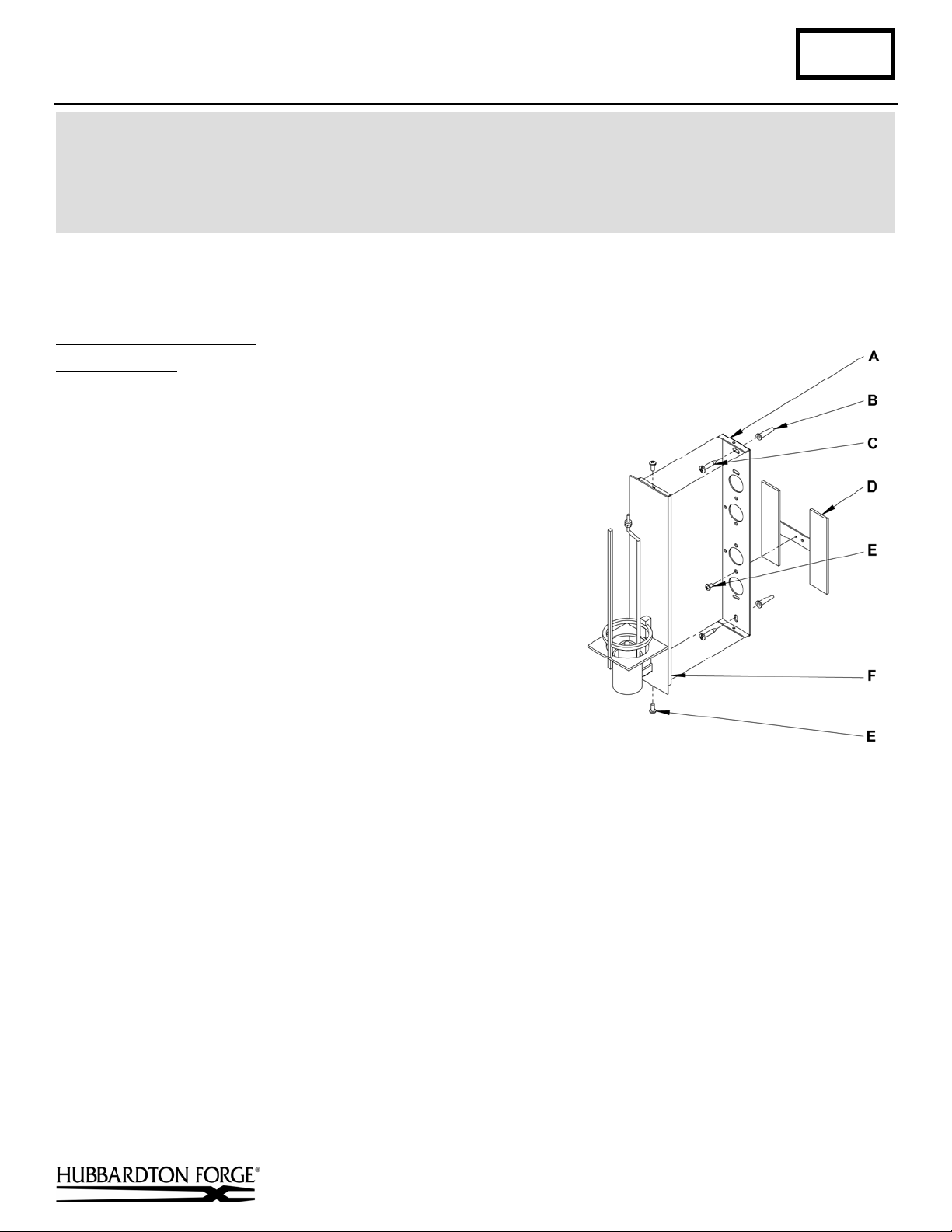
To Mount Fixture to Wall (Figure 1)
Component Parts
A Wall Mounting Bracket
B Anchors (2)
C #10 Screws (2)
D Electric Box Cover
(for 4” Outlet box)
Caution: Be sure power is off at the main breaker box prior to
installation.
1. Carefully unpack the fixture from the carton.
2. Place the wall mounting bracket (A) over the electrical box using
one of the wiring holes provided being sure to hold it plum and
level. If using a single gang outlet box electric box, cover (D)
is not needed. Remove #8 black screw (E) from electric box
cover (D) and save for later use. Determine which electric box
cover (D) location works the best and attach to wall mounting
bracket (A). With a pencil, mark the location of all mounting
holes in the wall mount bracket on the wall behind.
IMPORTANT: Wall mounting bracket must be secured to a
solidly mounted to a framing member in at least two locations.
Do not depend on drywall anchors alone to support this fixture.
If in doubt, contact a qualified electrician.
Drill 1/4" holes in the locations marked on the wall. For holes
using anchors, place the tapered end of the anchors (B) into the holes and gently tap them flush to the
wall using a light weight hammer.
3. Thread the wires in the electrical box through the hole in the wall mounting bracket (A) while moving the bracket
into position. Using the 1" #10 screws (C), screw the bracket securely to the wall. Be careful not to over-tighten or
strip the anchors.
4. Hold the fixture assembly (F) close to the wall mounting bracket (A) and using suitable wire connectors (not
provided) connect fixture wires to supply wires (white to white, black to black, and bare copper or green to bare
copper or green). Ground the mounting bracket using the green ground wire fastened to the back of the fixture
assembly (F).
Caution: Make sure wire connectors are twisted on securely, and no bare wires are exposed.
5. Carefully tuck all wires behind the fixture assembly (F) and inside the wall mounting bracket (A) and place the
fixture over the bracket so the holes in the top and bottom match the threaded holes in the wall mounting bracket
(A). Secure the fixture by threading the #8 black screws (E) through the holes in the fixture assembly (F) and into
the wall mounting bracket (B).
6. Install light bulb.
Hand-Forged, Vermont-Made Lighting and Accessories
P.O. Box 827, 154 Route 30 South, Castleton, Vermont 05735
e noted on fixture. Use only recommended bulbs with fixture.
E #8 Black Screws (3)
F Fixture Assembly
Figure 1
(continued)
19867 Rev B
Page 2
Assembly & Installation Instructions B117
For 20-7858 After Hours Wall Sconce Page 2 of 2
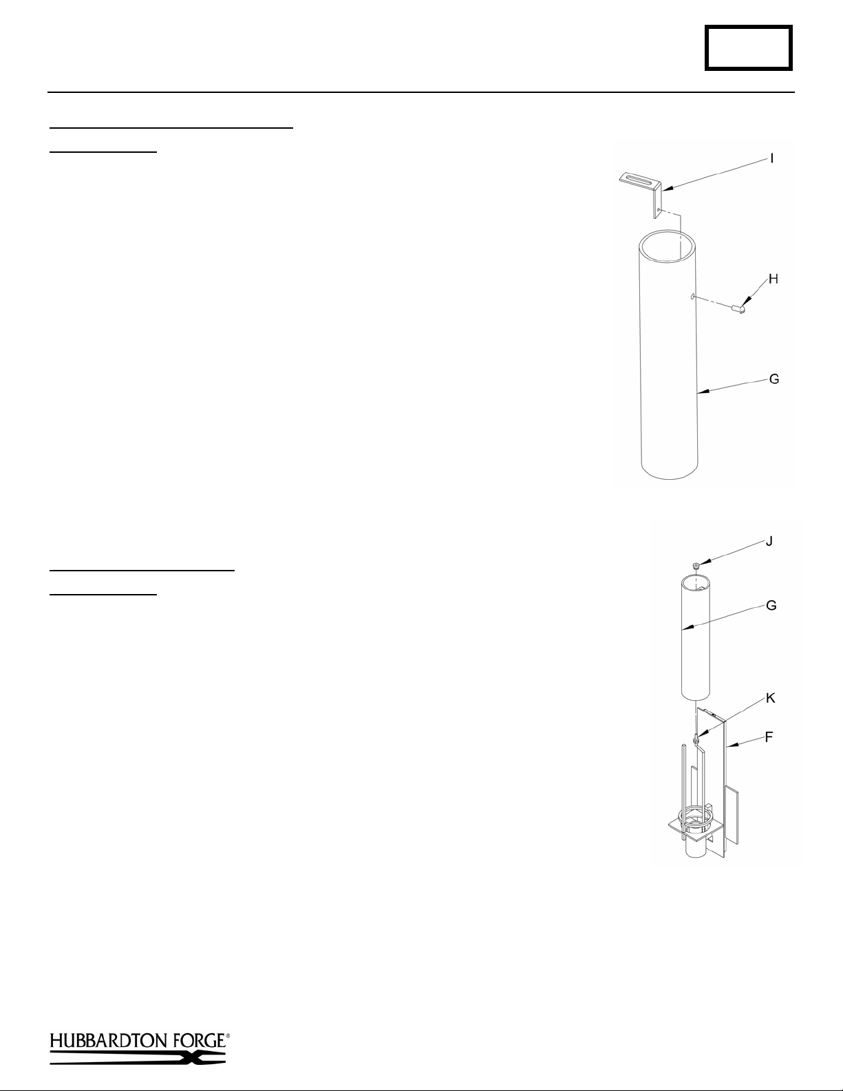
To Install Glass Mounting Bracket (Figure 2)
Component Parts
G Glass
H Screw
I Glass Mounting Bracket
1. Remove screw (B) from glass mounting bracket (C). Save for later use. Screw
is shipped installed in bracket.
2. Slide glass mounting bracket (I) inside end of the glass (G) that has drilled
hole.
3. Align small threaded hole in glass mounting bracket (I) with hole in glass (G).
4. Attach glass mounting bracket (I) to glass (G) with screw (H). Do not over
tighten.
Figure 2
To Install Glass to Fixture
Component Parts
F Fixture
G Glass
J Nylon Nut
K Threaded Rod
(Figure 3)
1. Remove nylon nut (J) from fixture and save for later use.
2. Align glass (G) so that mounting bracket is at the top of the glass.
3. Slide glass (G) over light bulbs until it stops at bottom of fixture (F).
4. Thread nylon nut (J) onto threaded rod (K) until tight.
Note: This fixture can be mounted as shown or in reverse.
Figure 3
If you need further assistance, or find that you are missing any parts, please contact the dealer from which you purchased
this product. We hope you enjoy your fixture!
* Hubbardton Forge will not be liable for injury or damage caused by improper installation, lamping or use of this fixture.
Hand-Forged, Vermont-Made Lighting and Accessories
P.O. Box 827, 154 Route 30 South, Castleton, Vermont 05735
19867 Rev B
 Loading...