

Page 1
Installation Instructions B170
For Sconce 20-4825 & 20-4825E Page 1 of 3
CAUTION: FAILURE TO INSTALL THIS FIXTURE PROPERLY MAY RESULT IN SERIOUS PERSONAL
INJURY OR DEATH AND PROPERTY DAMAGE. We recommend installation by a licensed electrician.
This product must be installed in accordance with applicable installation code(s), by a person familiar with the
construction and operation of the product and the hazards involved.*
Caution: Do not exceed maximum wattage noted on fixture. Use only recommended bulbs with fixture.
Please Note: This fixture is designed to be mounted on a standard wall surface and may not be suitable for all
applications. If installing in a non-wood frame application, we recommend consulting a qualified builder or electrician.
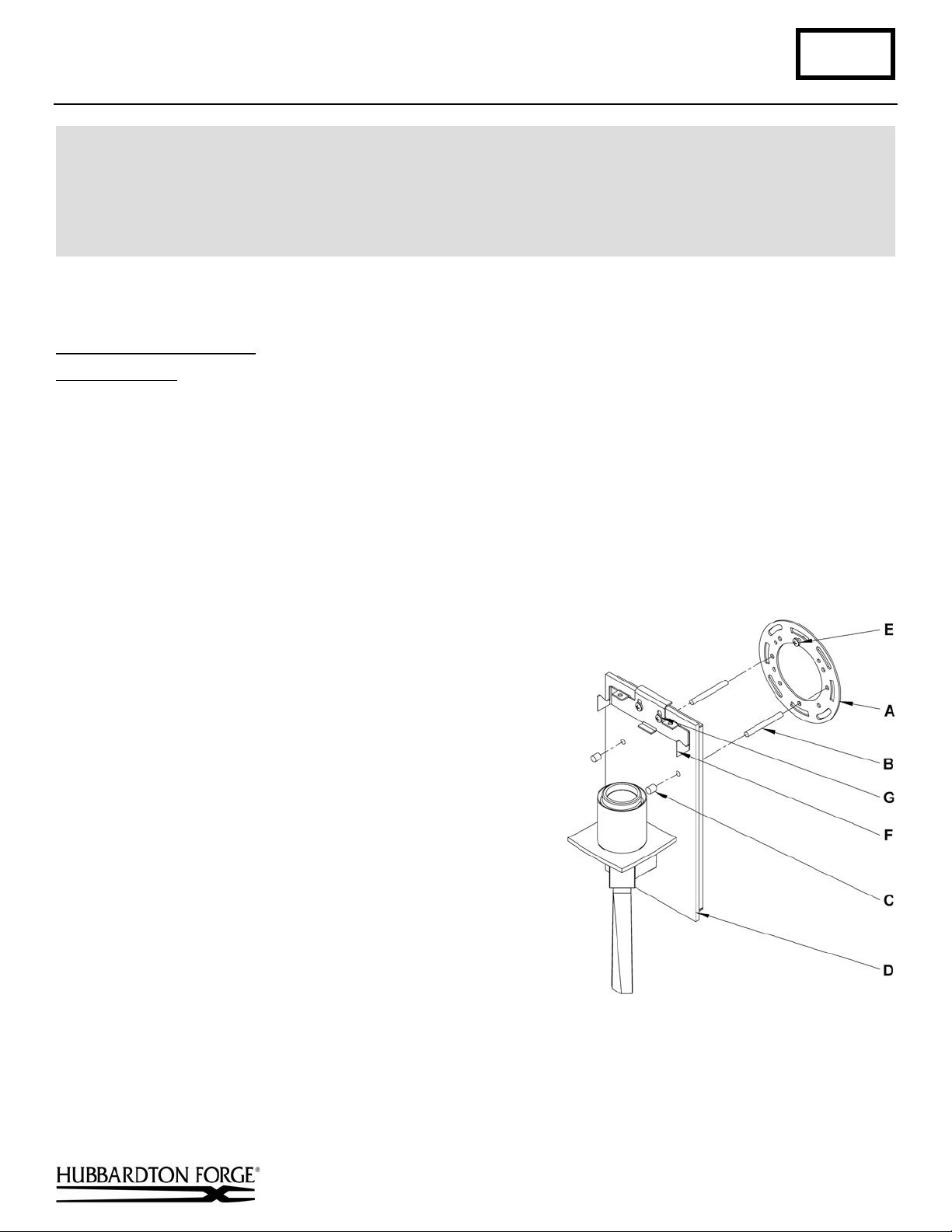
To Mount Fixture to Wall (Figure 1)
Component Parts
A Crossbar
B Threaded Stud (2)
C Barrel Knob (2)
D Fixture Assembly
E Ground Screw
F Bracket
G 8-32 Screw (2)
Caution: Be sure power is off at the main breaker box prior to installation.
1. Carefully unpack the fixture from the carton.
2. Remove bracket (F) by loosening and removing the two
8-32 screws (G). Set to the side for later use.
Note: This is only necessary for the shade option.
Using two machine screws (not provided), fasten the
3.
crossbar (A) to the electric box making sure that fixture
mounting holes are level.
Note: A new electric box comes with screws. When
replacing a fixture, retain the existing screws for use
with the new fixture.
4. Thread studs (B) into the appropriate holes in the crossbar
(A). Adjust the studs to proper length to ensure the fixture
will fit snugly to the wall.
5. Hold the fixture assembly (D) close to the wall and using
suitable wire connectors, not provided, connect fixture
wires to supply (white to white or ribbed and black to
black or smooth). Connect all ground wires to ground
screw.
Caution: Make sure wire connectors are twisted on
securely, and no bare wire is exposed.
6. Slide fixture assembly (D) over threaded studs (B) and
push firmly to wall, making sure that no wires are pinched
between fixture back and wall. Fasten with barrel knobs (C).
Be sure threaded studs (B) are fully seated in the barrel
knobs (C).
7. See instructions on next page to install glass or shade depending on option purchased.
(Figure 1)
(continued)
Hand-Forged, Vermont-Made Lighting and Accessories
P.O. Box 827, 154 Route 30 South, Castleton, Vermont 05735
22659
Page 2
Installation Instructions B170
For Sconce 20-4825 & 20-4825E Page 2 of 3
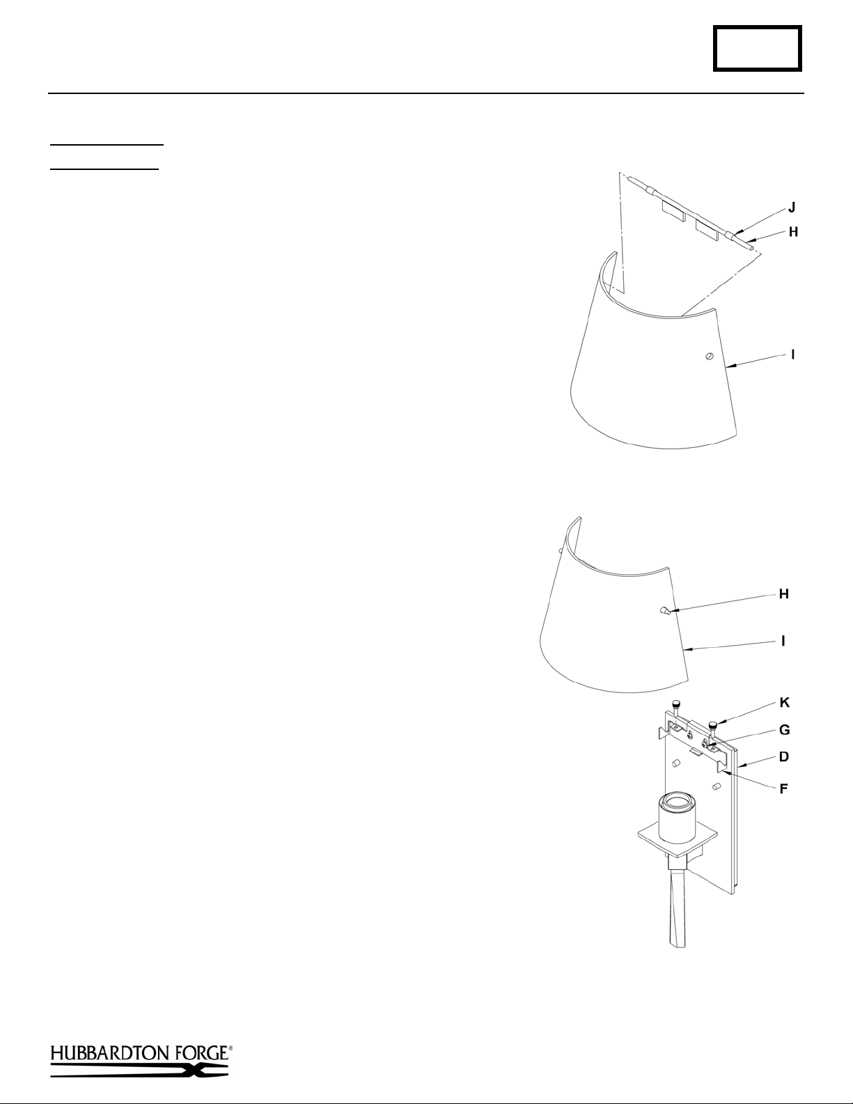
To Install Glass
Component Parts
(Figures 2 & 3)
D Fixture Assembly
F Bracket
G 8-32 Screw (2)
H Hanger Rod
I Glass
J Rubber tubing (2)
K Thumb Screw (2)
1. Slide hanger rod (H) into holes in glass (I) from the inside.
2. Move rubber tubing (J) outward on rod to secure rod in glass,
making sure the rod remains centered in the glass.
3. Install thumb screws (K) into bracket (F). Only a couple of
threads engaged at this time.
4. Place glass (I) with hanger rod installed into bracket. Make sure
tabs are pointing down. Some pressure is necessary to snap rod
into bracket. Check glass for level and adjust as needed by
loosening 8-32 screws (G) and moving bracket as needed. Once
glass is level tighten both 8-32 screws (G).
5. Tighten thumb screws (K).
6. Install light bulb. (Fluorescent supplied with fixture)
7. Restore electricity at main breaker.
(Figure 2)
Hand-Forged, Vermont-Made Lighting and Accessories
P.O. Box 827, 154 Route 30 South, Castleton, Vermont 05735
(Figure 3)
(continued)
22659
Page 3
Installation Instructions B170
For Sconce 20-4825 & 20-4825E Page 3 of 3
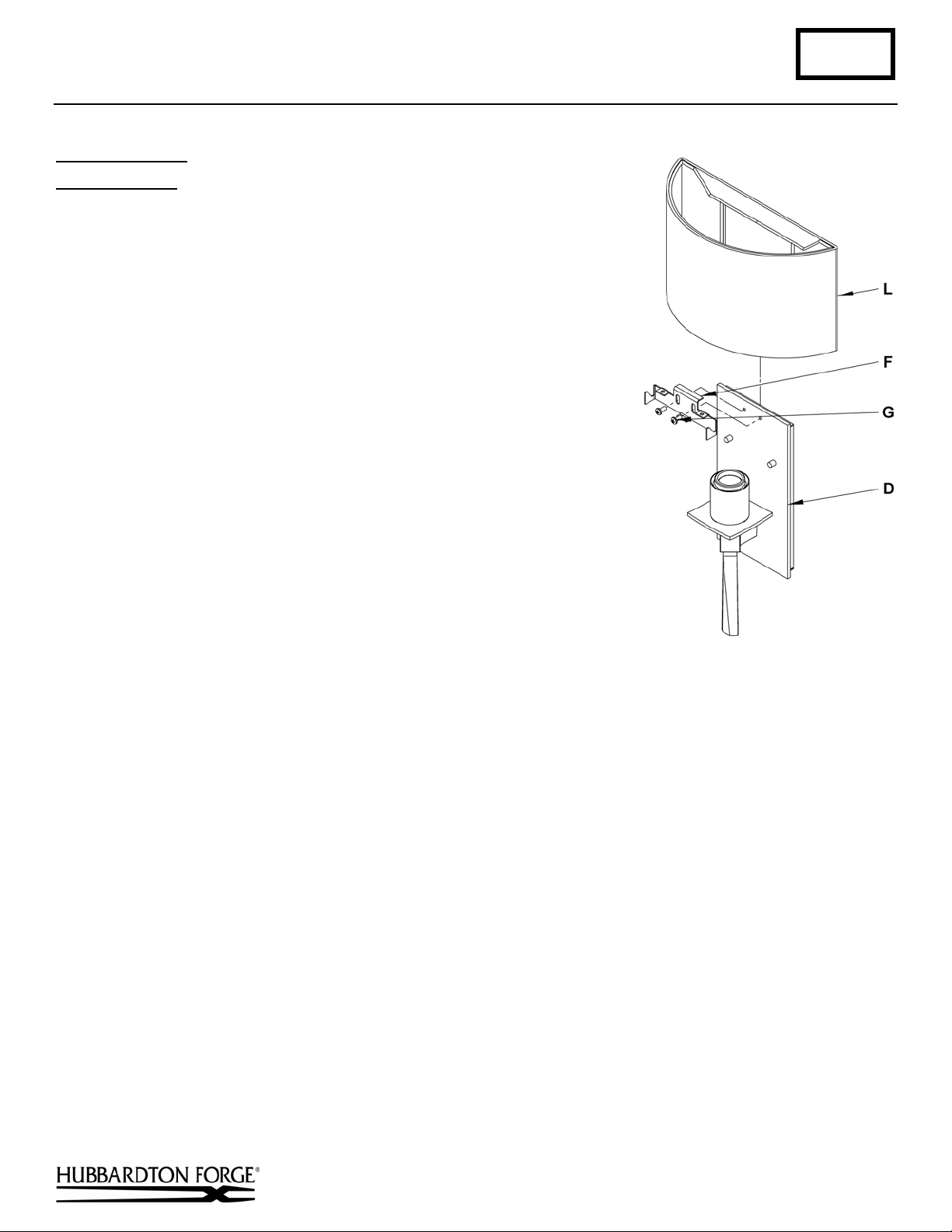
To Install Shade
Component Parts
D Fixture Assembly
F Bracket
G 8-32 Screw (2)
L Shade
1. Slip shade (L) onto fixture assembly (D) so it rests against wall.
2. Attach bracket (F) to fixture assembly (D) with two 8-32
screws (G).
3. Install light bulb. (Fluorescent supplied with fixture)
4. Restore electricity at main breaker.
If you need further assistance, or find that you are missing any parts, please contact the dealer from which you purchased
this product. We hope you enjoy your fixture!
(Figure 4)
(Figure 4)
* Hubbardton Forge will not be liable for injury or damage caused by improper installation, lamping or use of this fixture.
Hand-Forged, Vermont-Made Lighting and Accessories
P.O. Box 827, 154 Route 30 South, Castleton, Vermont 05735
22659
 Loading...