

Page 1
Installation Instructions B272
CAUTION: FAILURE TO INSTALL THI S FIXTURE PROPERLY MAY RESULT I N SERIO US PERSO NAL
(Figure 1)
Echo Sconce 204320 Page 1 of 3
INJURY OR DEATH AND PROPERTY DAMAGE. We rec o mm e nd installation by a licensed electrician.
This product must be installed in accordance with applic able insta ll ation co de( s) , by a person familiar with the
construction and operation of the product and the hazards involved.*
Caution: Do not exceed maximum wattage noted on fixture. Use only recommended bulbs with fixture.
Caution: This fixture is designed to be mounted on a standard wall surface and may not be suitable for all applications. If
installing in a non-wood frame application, we recommend consulting a qualified builder or electrician.
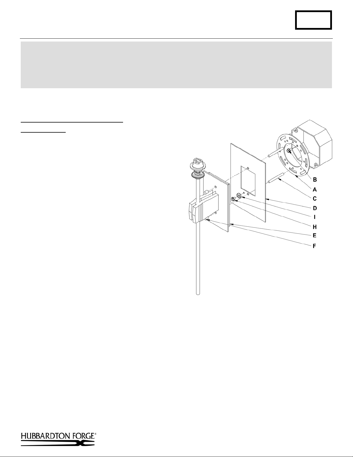
To Mount Fixture to Standard Box (Figure 1)
Component Parts
A Crossbar
B Crossbar Ground Scre w
C Threaded Studs Long (2)
D 4” Box Cover
E Fixture
F Threaded Knobs (2)
H Ground Screw
I Cupped Washer
Caution: Be sure power is off at the main breaker box prior to installation.
1. Carefully unpack the fixture from the carton.
2. Using two machine screws (not provided),
fasten the crossbar (A) to the electric box
making sure crossbar is level.
Note: A new electric box comes with screws.
When replacing a fixture, retain the existing
screws for use with the new fixture
3. Screw threaded studs (C) into the crossbar (A).
Adjust the th rea ded stud s (C) to proper length to
ensure the fixture (E) will fit snugly to the wall.
4. Run a pigtail lead from crossbar ground screw
(B) to the junction box.
5. Slip the 4” box cover (D) onto the threaded studs (C).
6. Attach a pigtail lead to ground screw (H) and cupped washer (I).
7. Hold the fixture assembly (E) close to the wall and using suitable wire connectors (not provided) connect fixture
wires to supply (white to white or ribbed and black to black or smooth). Connect all ground wires (bare copper or
green to bare copper or green).
Caution: Make sure wire connectors are twisted on securely, and no bare wire is exposed.
8. Place fixture (E) firmly against the wall and fasten with threaded knobs (F).
9. See instructions on last pag e to ins tall glass.
.
(continued)
Hand-Forged, Vermont-Made Lighting and Accessories
154 Route 30 South, Castleton, Vermont 05735
27786 A
Page 2
Installation Instructions B272
(Figure 2)
Echo Sconce 204320 Page 2 of 3
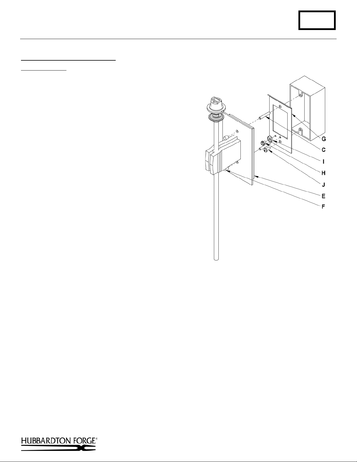
To Mount Fixture to Single Box (Figure 2)
Component Parts
C Threaded Studs Short (2)
E Fixture
F Threaded Knobs (2)
G Single Box Crossbar
H Gr ound Scr e w
I Cupped Washer
J #8 Screw
Caution: Be sure power is off at the main breaker box prior to installation.
1. Carefully unpack the fixture from the carton.
2. Screw one threaded stud (C) into the top hole of the
electrical box.
3. Orient the single box crossbar (G) so tha t the ben t tab is
at the top and bent away from the wall. The tab will fit
into the back of the fixture to facilitate alignment. Slip
single box crossbar (G) over threaded stud (C). Secure
single box crossbar (G) but threading #8 screw (J) into
electrial box.
4. Attach a pigtail lead to ground screw (H) and cupped
washer (I).
5. Hold the fixture assembly (E) close to the wall and using
suitable wire connectors (not provided) connect fixtu r e
wires to supply (white to white or ribbed and black to
black or smooth). Connect all ground wires (bare copper
or green to bare copper or green).
Caution: Make sure wire connectors are twisted on securely, and no bare wire is exposed.
6. Place fixture (E) firmly against the wall and fasten with threaded knobs (F).
7. See instructions following to install glass.
(continued)
Hand-Forged, Vermont-Made Lighting and Accessories
154 Route 30 South, Castleton, Vermont 05735
27786 A
Page 3

Installation Instructions B272
(Figure 3)
Echo Sconce 204320 Page 3 of 3
To Install Glass (Figure 3)
Component Parts
K Socket
L Bulb (Included)
M Glass
N Retaining Ring
O Retaining Ring Tool
1. Remove retaining ring (N) from socket (K). Retaining Rings are shipped
installed.
2. Install bulb (L). Be careful not to touch bulb with bare hands; oil from the hands
will dramatically reduce bulb life
3. Slip glass (M) over socket (K).
4. Thread retaining ring (N) onto socket (K) using provided retaining ring tool (O)
until it rests on inside of glass (M). Do not over tighten.
5. Restore electricity at main breaker.
If you need further assistance, or find that you are missing any parts, please contact the dealer from which you purchased
this product. We hope you enjoy your fixture!
* Hubbardton Forge will not be liable for injury or damage caused by improper installation, lamping or use of this fixture.
Hand-Forged, Vermont-Made Lighting and Accessories
154 Route 30 South, Castleton, Vermont 05735
27786 A
 Loading...