

Page 1
Assembly & Installation Instructions A129
For Tryne Chandelier 19-443010 & 19-443610 Page 1 of 3 _
CAUTION: FAILURE TO INSTALL THIS FIXTURE PROPERLY MAY RESULT IN SERIOUS PERSONAL
INJURY OR DEATH AND PROPERTY DAMAGE. We recommend installation by a licensed electrician.
This product must be installed in accordance with applicable installation code(s), by a person familiar with the
construction and operation of the product and the hazards involved.*
Caution: Do not exceed maximum wattage noted on fixture. Use only recommended bulbs with fixture.
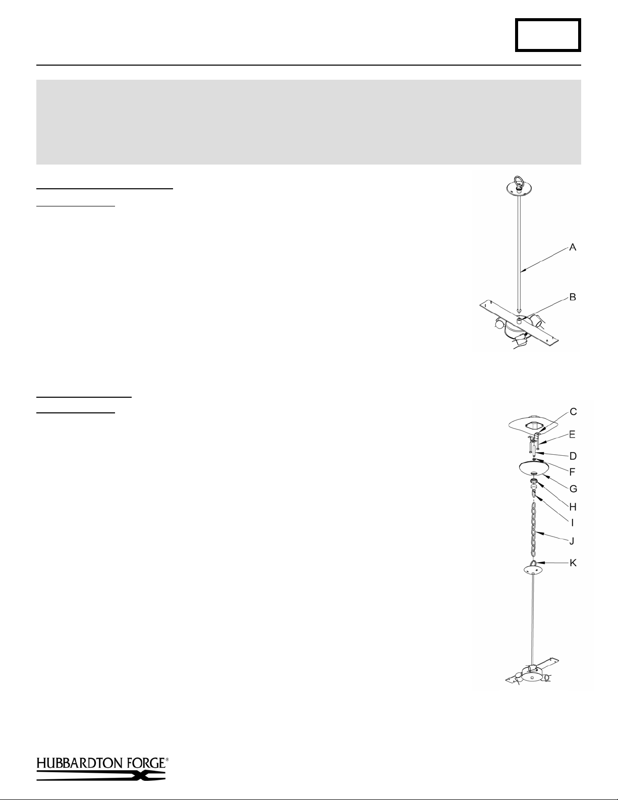
To Attach Stem Assembly (Figure 1)
Component Parts
A Stem Assembly
B Fixture Coupling
1. Carefully unpack the fixture from the carton.
2. Carefully thread stem assembly (A), threaded end first, over fixture wires.
3. Apply a drop of the supplied thread locking compound to the internal threads of fixture
coupling (B) and screw into fixture, being careful not to twist the wires.
Note: Application of the thread locking compound is necessary to prevent the stem
from loosening during regular maintenance and cleaning of the fixture. Be certain to
apply the compound.
4. See instructions below to complete the installation.
(Figure 1)
Install the Canopy (Figure 2)
Component Parts
C Crossbar
D Threaded Nipple
E Lag Screw (2)
F Lock Nut
G Canopy
Caution: Be sure power is off at the main breaker box prior to installation.
Caution: This fixture must be supported independently of an outlet box. Crossbar is designed
to fit in the bottom of a standard metal 4” octagonal outlet box.
H Loop Collar
I Threaded Loop
J Chain
K Fixture Loop
1. Drill two holes through the back of the outlet box and using two lag screws (E) attach
cross bar (C) to a structural member in the ceiling, centering the crossbar in the outlet
box. We've supplied lag screws with your fixture; however, different materials and/or
construction methods may require different fasteners. If in doubt, contact a qualified
electrician.
2. Thread lock nut (F) and threaded loop (I) onto threaded nipple (D), then place canopy
(G) over threaded loop and adjust nipple length to ensure a snug canopy fit. Once the
length is determined, set the canopy aside and lock nipple position by tightening the
locknut (F) against the crossbar (C).
3. Attach one end of the chain (J) to the fixture loop (K).
Hand-Forged, Vermont-Made Lighting and Accessories
P.O. Box 827, 154 Route 30 South, Castleton, Vermont 05735
20610
(Figure 2)
(continued)
Page 2
Assembly & Installation Instructions A129
For Tryne Chandelier 19-443010 & 19-443610 Page 2 of 3 _
4. Attach the other end of the chain to the threaded loop (I) and thread the fixture wires through every other link of
the chain (J) and up through the threaded loop (I) and nipple (D) into the outlet box.
5. Using suitable wire connectors (not provided), connect fixture wires to supply wires (white or ribbed side of
fixture cord to white supply, black or smooth side of fixture cord to black supply, and bare copper to bare copper
or green supply). Push wires back into outlet box.
Caution: Make sure wire connectors are twisted on securely, and no bare wire is exposed.
6. Slide the canopy up the chain and over the threaded loop (I), securing with loop collar (H). Make sure no wires
are pinched between the canopy (G) and the ceiling or crossbar
(C).
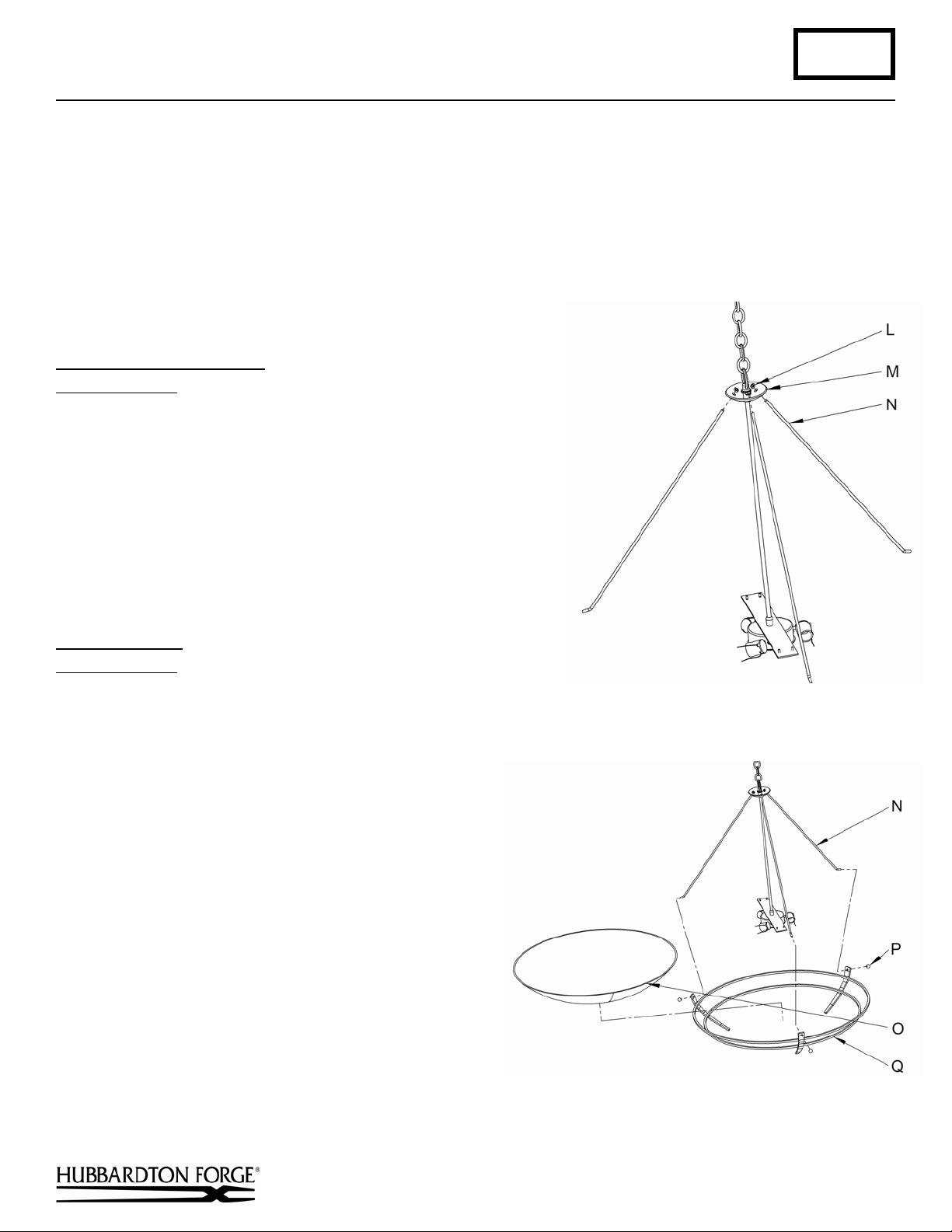
Install the Threaded Rods
Component Parts
L Hex Nut (4)
M Bob
N Threaded Rod (4)
1. Slip straight end of threaded rod (N) through holes in bob (M).
2. Thread hex nut (L) onto threaded rod (N) until bottomed out and
snug.
3. Lower threaded rod (N) until hex nut (L) sits flat inside bob (M).
To Install Glass
Component Parts
N Threaded Rod (3)
O Glass
P Threaded Ball (3)
Q Ring Assembly
(Figure 4)
1. Install light bulbs prior to installing glass.
2. Insert the ends of two of the threaded rods (N) through
two of the holes in the ring assembly (Q). Secure with
threaded balls (P).
3. Place glass (O) in ring assembly. Insert remaining
support rod, securing with remaining threaded ball.
4. Level glass as needed.
(Figure 3)
(Figure 3)
Hand-Forged, Vermont-Made Lighting and Accessories
P.O. Box 827, 154 Route 30 South, Castleton, Vermont 05735
(Figure 4)
(continued)
20610
Page 3
Assembly & Installation Instructions A129
For Tryne Chandelier 19-443010 & 19-443610 Page 3 of 3 _
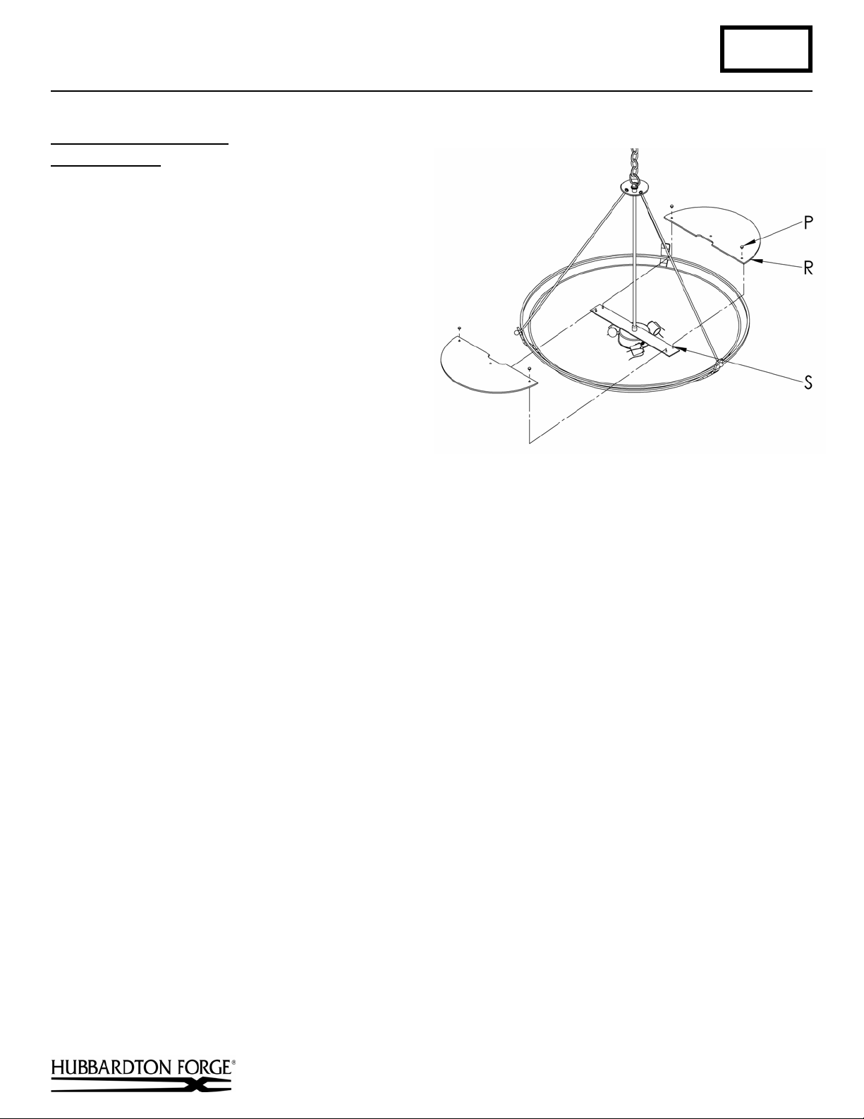
To Install Diffuser Glass
Component Parts
P Threaded Ball (4)
R Diffuser Glass (2)
S Threaded Stud (4)
1. Slip diffuser glass (R) over threaded stud (S).
2. Install threaded ball (P) on to threaded stud (S) until
snug against diffuser glass (R). Be careful not to
over tighten.
3. Restore electricity at main breaker.
If you need further assistance, or find that you are missing any parts, please contact the dealer from which you purchased
this product. We hope you enjoy your fixture!
* Hubbardton Forge will not be liable for injury or damage caused by improper installation, lamping or use of this fixture.
(Figure 4)
(Figure 5)
Hand-Forged, Vermont-Made Lighting and Accessories
P.O. Box 827, 154 Route 30 South, Castleton, Vermont 05735
20610
 Loading...