

Page 1
Assembly & Installation Instructions A226
For Single Ellipse Pendants 18-825 & 18-825F Page 1 of 3
CAUTION: FAILURE TO INSTALL THIS FIXTURE PROPERLY MAY RESULT IN SERIOUS PERSONAL
INJURY OR DEATH AND PROPERTY DAMAGE. We recommend installation by a licensed electrician.
This product must be installed in accordance with applicable installation code(s), by a person familiar with the
construction and operation of the product and the hazards involved.*
Caution: Do not exceed maximum wattage noted on fixture. Use only recommended bulbs with fixture.
Please Note: Pendant 18-820 shown in illustrations.
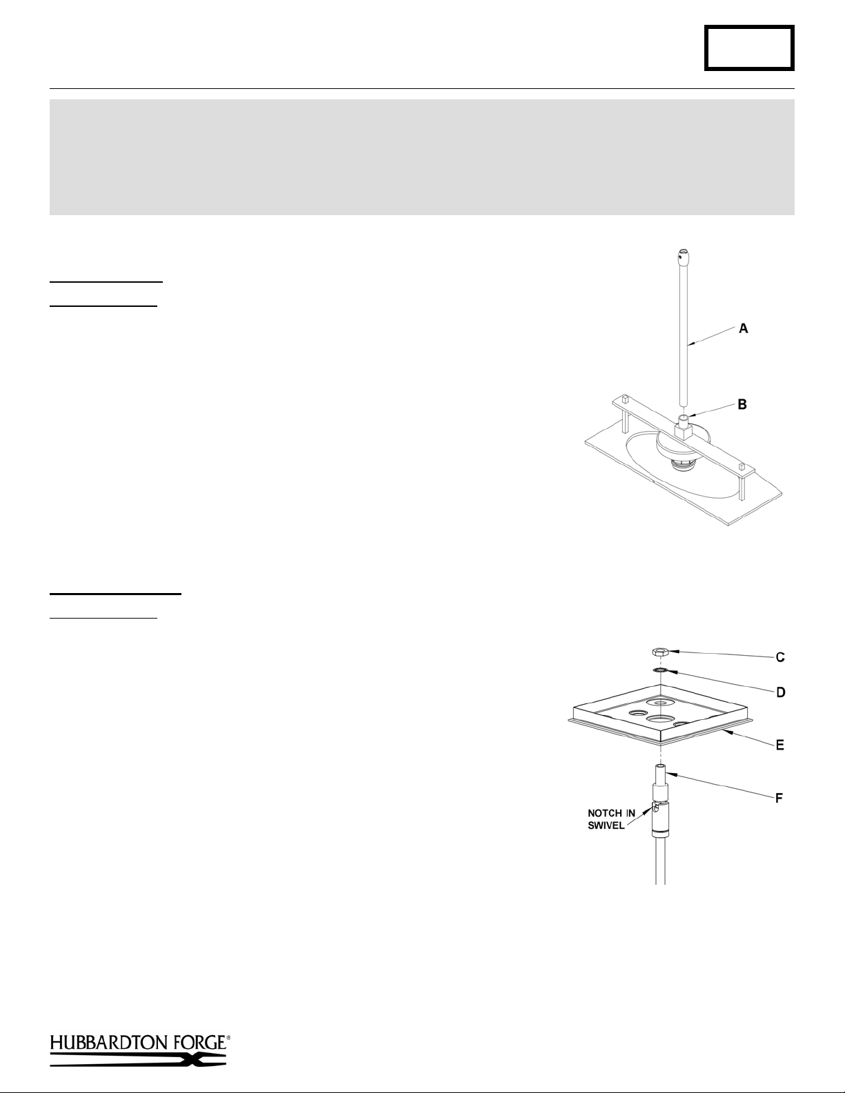
Stem Assembly
Component Parts
A Fixture Pipe
B Fixture Coupling
(Figure 1)
1. Carefully unpack the fixture from the carton.
2. Carefully thread fixture pipe (A), threaded end first, over fixture wires.
3. Apply a drop of the supplied thread locking compound to the internal
threads of fixture coupling (B) and screw stem into fixture, being careful
not to twist or pinch the wires.
Note: Application of the thread locking compound is necessary to prevent
the stem from loosening during regular maintenance and cleaning of the
fixture. Be certain to apply the compound.
4. See instructions below to complete the installation.
Assemble Canopy
Component Parts
C Hex Nut
D Lock Washer
E Canopy
F Nipple
(Figure 2)
1. Insert nipple (F) in swivel up through hole in canopy (E).
2. Place lock washer (D) and nut (C) onto the nipple (G) in swivel and
tighten securely.
Note: If installing on a sloped ceiling, make certain that the notch in
the swivel portion of the stem is oriented toward the downward side of
the slope.
(Figure 1)
Hand-Forged, Vermont-Made Lighting and Accessories
P.O. Box 827, 154 Route 30 South, Castleton, Vermont 05735
(Figure 2)
(continued)
23909
Page 2
Assembly & Installation Instructions A226
For Single Ellipse Pendants 18-825 & 18-825F Page 2 of 3
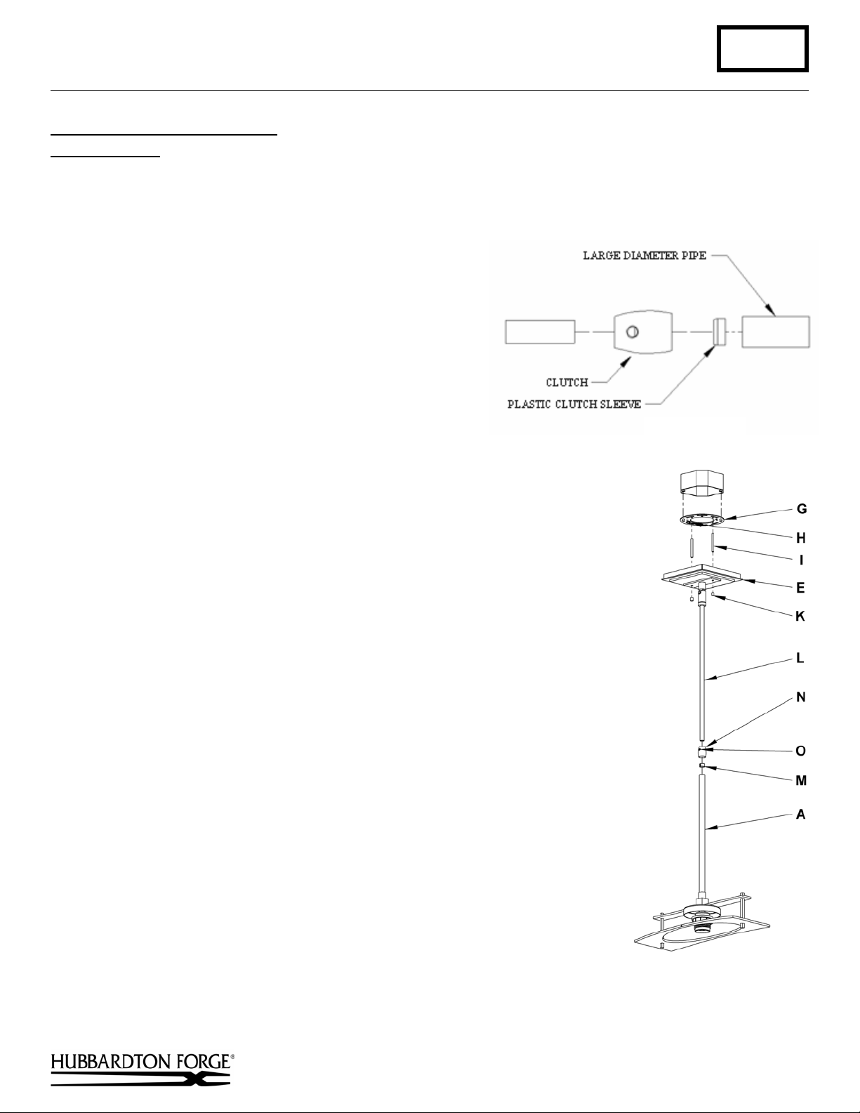
To Complete Fixture Assembly
Component Parts
A Fixture Pipe
E Canopy
G Crossbar
H Ground Screw
Caution: Be sure power is off at the main breaker box
prior to installation.
(Figures 3 & 4)
I Threaded Stud (2)
K Barrel Knob (2)
L Canopy Pipe
M Plastic Clutch Sleeve
1. Thread the wires from the fixture pipe (A) into and
through the canopy pipe (L) up through the canopy (E).
2. Unscrew the clutch (N) from the fixture pipe (A); slide it
across the wires and onto the canopy pipe (L). Follow this
with the plastic clutch sleeve (M), oriented so the tapered
end of the clutch sleeve nests in the clutch. (
Figure 3)
Slide the canopy pipe (L) as far necessary to give you the
total length of the fixture which you desire. Be careful not
to scratch the pipe surfaces and to pull excess wire up
through the canopy pipe (L). Screw clutch (N) onto fixture pipe (A). There
must be a minimum 1-1/2" of inner pipe inside the outer pipe. Hand-tighten the
clutch to temporarily hold this adjustment. The clutch is not securely fastened
at this point; do not depend on it to hold the fixture.
Important: To ensure full connection strength, be sure the tapered end of the
plastic clutch sleeve is oriented toward the clutch when assembled and
securely tighten set screw (Figure 3).
3. Thread studs (I) through appropriate holes in crossbar (G) to match holes in
canopy (E).
4. Using two machine screws (not provided), fasten the crossbar (G) to the
electric box.
Note: A new electric box comes with screws. When replacing a fixture, retain the
existing screws for use with the new fixture.
5. Using suitable wire connectors (not provided) connect fixture wires to supply
(white to white or ribbed and black to black or smooth). Connect all ground
wires to green ground screw (H).
Caution: Make sure wire connectors are twisted on securely, and no bare wire is
exposed.
6. Slide canopy (E) over threaded studs (I) and push firmly to ceiling, making
sure that no wires are pinched between fixture canopy and ceiling. Fasten with
barrel knobs (K). Be sure studs are fully seated in the barrel knobs.
7. Once the fixture is fastened to the ceiling, tighten the set screw (O) in clutch
(N) firmly with hex wrench provided. Only after the set screw (O) is tight
should you install the glass.
8. Refer instructions below and install glass.
N Clutch
O Set Screw
(Figure 3)
Hand-Forged, Vermont-Made Lighting and Accessories
P.O. Box 827, 154 Route 30 South, Castleton, Vermont 05735
(Figure 4)
(continued)
23909
Page 3

Assembly & Installation Instructions A226
For Single Ellipse Pendants 18-825 & 18-825F Page 3 of 3
To Install Glass
Component Parts
P Socket
Q Glass
R Retaining Ring
(Figure 5)
1. Remove retaining ring (R) from socket (P). Retaining Ring is
shipped installed.
2. Slip glass (Q) over socket (P).
3. Thread retaining ring (R) onto socket until it rests on inside of
glass (Q). Do not over tighten.
4. Install light bulb (F version bulb is included) and restore
electricity at main breaker.
(Figure 5)
If you need further assistance, or find that you are missing any parts, please contact the dealer from which you purchased
this product. We hope you enjoy your fixture!
* Hubbardton Forge will not be liable for injury or damage caused by improper installation, lamping or use of this fixture.
Hand-Forged, Vermont-Made Lighting and Accessories
P.O. Box 827, 154 Route 30 South, Castleton, Vermont 05735
23909
 Loading...