

Page 1

Assembly & Installation Instructions A58
For Adjustable Pendant Models 18-773 & 18-775 Page 1 of 2
CAUTION: FAILURE TO INSTALL THIS FIXTURE PROPERLY MAY RESULT IN SERIOUS PERSONAL
CAUTION: FAILURE TO INSTALL THIS FIXTURE PROPERLY MAY RESULT IN SERIOUS PERSONAL
INJURY OR DEATH AND PROPERTY DAMAGE. We recommend installation by a licensed electrician.
INJURY OR DEATH AND PROPERTY DAMAGE. We recommend installation by a licensed electrician.
This product must be installed in accordance with applicable installation code(s), by a person familiar with the
This product must be installed in accordance with applicable installation code(s), by a person familiar with the
construction and operation of the product and the hazards involved.*
construction and operation of the product and the hazards involved.*
Caution: Do not exceed maximum wattage noted on fixture. Use only recommended bulbs with fixture.
Caution: Do not exceed maximum wattage noted on fixture. Use only recommended bulbs with fixture.
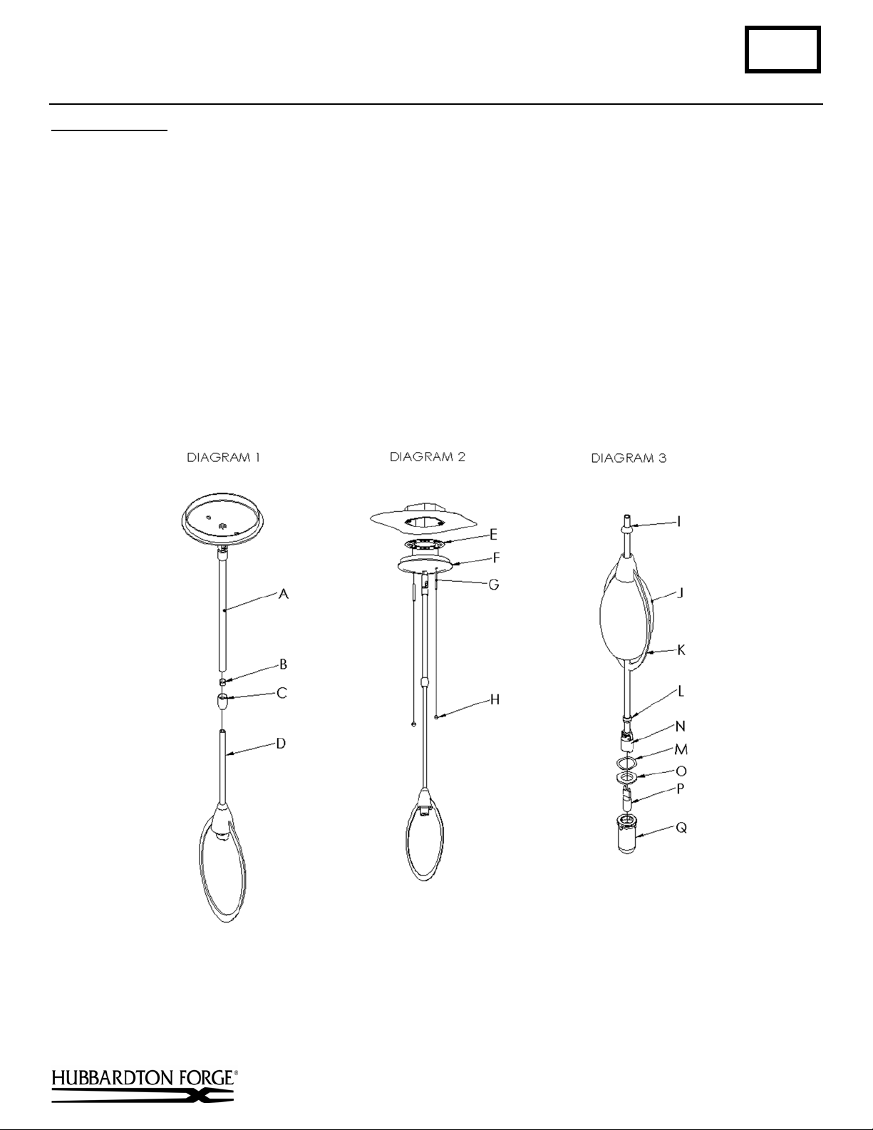
Component Parts
A Canopy Pipe
B Clutch Sleeve
C Clutch
D Fixture Pipe
E Crossbar
F Canopy
G Threaded Studs (2)
H Knurled Balls (2)
I Locking Nut
J Glass
K Frame
L Bushing
To Assemble (Please refer to Diagram 1 on next page.)
1. Carefully unpack the fixture from the carton.
Thread the wires from the fixture pipe (D) into and through the canopy pipe (A) and up through the canopy (F).
Unscrew the clutch (C) from the canopy pipe, slide it across the wires and onto the smaller diameter fixture pipe.
Follow this with the clutch sleeve (B), so that the clutch sleeve nests in the clutch.
Important: To ensure full connection strength, be sure the tapered end of the plastic clutch sleeve is oriented
toward the clutch when assembled and securely tighten set screw.
2. Slide the smaller pipe as far as necessary to give you the total length of the fixture which you desire. Be careful
not to scratch the pipe surfaces and to pull excess wire up through the canopy. There must be a minimum 1-1/2"
of inner pipe inside the outer pipe. There must be a minimum of 6-1/2" between the clutch and the locking
nut to allow for bulb replacement. Hand-tighten the clutch to temporarily hold this adjustment.
At this point the adjustment is not securely fastened; do not depend on it to permanently hold the fixture.
M Retaining Spring
N Socket
O Retaining Ring
P G9 Bulb
Q Glass Shield
To Install Fixture
Caution: Be sure power is off at the main breaker box prior to installation.
Thread studs (G) through appropriate holes in the crossbar (E) to match hole centers on canopy. Using two
1.
(Please refer to Diagram 2 on next page.)
machine screws, fasten the crossbar to the electric box using outer oval slots to orient fixture to desired hanging
position.
Note: A new electric box comes with screws. When replacing a fixture, retain the existing screws for use with the
new fixture.
Using suitable wire connectors (not provided) connect fixture wires to supply (white to white and black to black ).
2.
Connect all ground wires to green ground screw.
Caution: Make sure wire connectors are twisted on securely, and no bare wire is exposed.
3. Slide canopy (F) with fixture attached, over threaded studs and push firmly to ceiling making sure that no wires
are pinched between fixture canopy and ceiling. Fasten with the knurled balls (H). Be sure studs are fully seated
in the knurled balls.
4. Check fixture for height (see assembly instructions). Tighten set screw in clutch with the supplied hex wrench
to securely fasten the fixture to the canopy.
(continued)
Hand-Forged, Vermont-Made Lighting and Accessories
P.O. Box 827, 154 Route 30 South, Castleton, Vermont 05735
16402 Rev A
Page 2
Assembly & Installation Instructions A58
For Adjustable Pendant Models 18-773 & 18-775 Page 2 of 2
To Install Glass (Please refer to Diagram 3.)
1. Unscrew locking nut (I) and slide locking nut, frame (K), and glass (J), small end up, up fixture stem.
2. While supporting glass and frame with one hand, place retaining spring (M) over socket and thread retaining ring
(O) onto socket until retaining ring is approximately halfway up socket.
3. Install bulb (P) in socket. Be careful not to touch bulb with bare hands. Oil from the hands will dramatically
reduce bulb life.
4. Thread glass shield (Q) onto socket just far enough to stay in place. Future bulb replacement can be accomplished
by snapping the glass from the holder rather than unscrewing the entire holder.
Caution: Keep glass shield in place when operating fixture.
5. Carefully lower glass, frame, and locking nut back into position and tighten locking nut, making sure glass and
frame are straight and level. Some adjustment of the retaining ring (O) may be required. If locking nut will not
start into the threads, adjust retaining ring lower on the socket. If threads are still showing when locking nut is
fully tightened, raise retaining ring on socket.
6. Restore electricity at main breaker box.
If you need further assistance, or find that you are missing any parts, please contact the dealer from which you purchased
this product. We hope you enjoy your fixture!
* Hubbardton Forge will not be liable for injury or damage caused by improper installation, lamping or use of this fixture.
Hand-Forged, Vermont-Made Lighting and Accessories
P.O. Box 827, 154 Route 30 South, Castleton, Vermont 05735
16402 Rev A
 Loading...