

Page 1
Assembly & Installation Instructions A275
CAUTION: FAILURE TO INSTALL THIS FIXTURE PROPERLY MAY RESULT IN SERIOUS PERSONAL
(Figure 1)
(Figure 2)
(Figure 1)
Erlenmeyer Pendant 18-710 Page 1 of 3
INJURY OR DEATH AND PROPERTY DAMAGE. We rec o mm e nd installation by a licensed electrician.
This product must be installed in accordance with applicable installation code(s), by a person familiar with the
construction and operation of the product and the hazards involved.*
Caution: Do not exceed maximum wattage noted on fixture. Use only recommended bulbs with fixture.
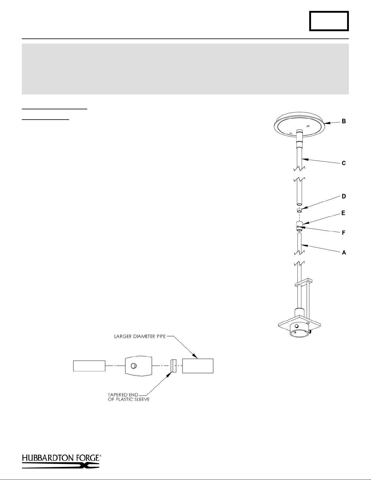
To Assemble Fixture (Figures 1 & 2)
Component Parts
A Fixture pipe
B Canopy
C Canopy pipe
1. Carefully unpack the fixture from the carton.
2. Slip the wires from the fixture pipe (A) into and through the canopy pipe (C)
up through the canopy (B).
3. Unscrew the clutch (E) from the canopy pipe (C); slide it across the wires and
onto the fixture pipe (A). Follow this with the plastic clutch sleeve (D),
oriented so the tapered end of the clutch sleeve nests in the clutch (Figure 2).
4. Slide the canopy pipe (C) as far as necessary to give you the total length of
the fixture which you desire. Be careful not to scratch the pipe surfaces and to
pull excess wire up through the canopy pipe (C). Screw clutch (E) onto
canopy pipe (C). There must be a minimum 1-1/2" of inner pipe inside the
outer pipe. Hand-tighten th e clutc h to temporarily ho ld thi s ad jus tment. The
clutch is not securely fastened at this point; do not depend on it to hold the
fixture.
Important: To ensure full connection strength, be sure the tapered end of the
plastic clutch sleeve is oriented toward the clutch when assembled and
securely tighten set screw (Figure 2).
5. Stop. Please see installation instructions on next page.
6. Once the fixture is fastened to the ceiling, tighten the set screw (F) firmly
with hex wrench provided. Only after the set screw (F) is tight should you
install the glas s.
D Clutch sleeve
E Clutch
F Set Sc r e w
(continued)
Hand-Forged, Vermont-Made Lighting and Accessories
154 Route 30 South, Castleton, Vermont 05735
26491
Page 2
Assembly & Installation Instructions A275
(Figure 3)
Erlenmeyer Pendant 18-710 Page 2 of 3
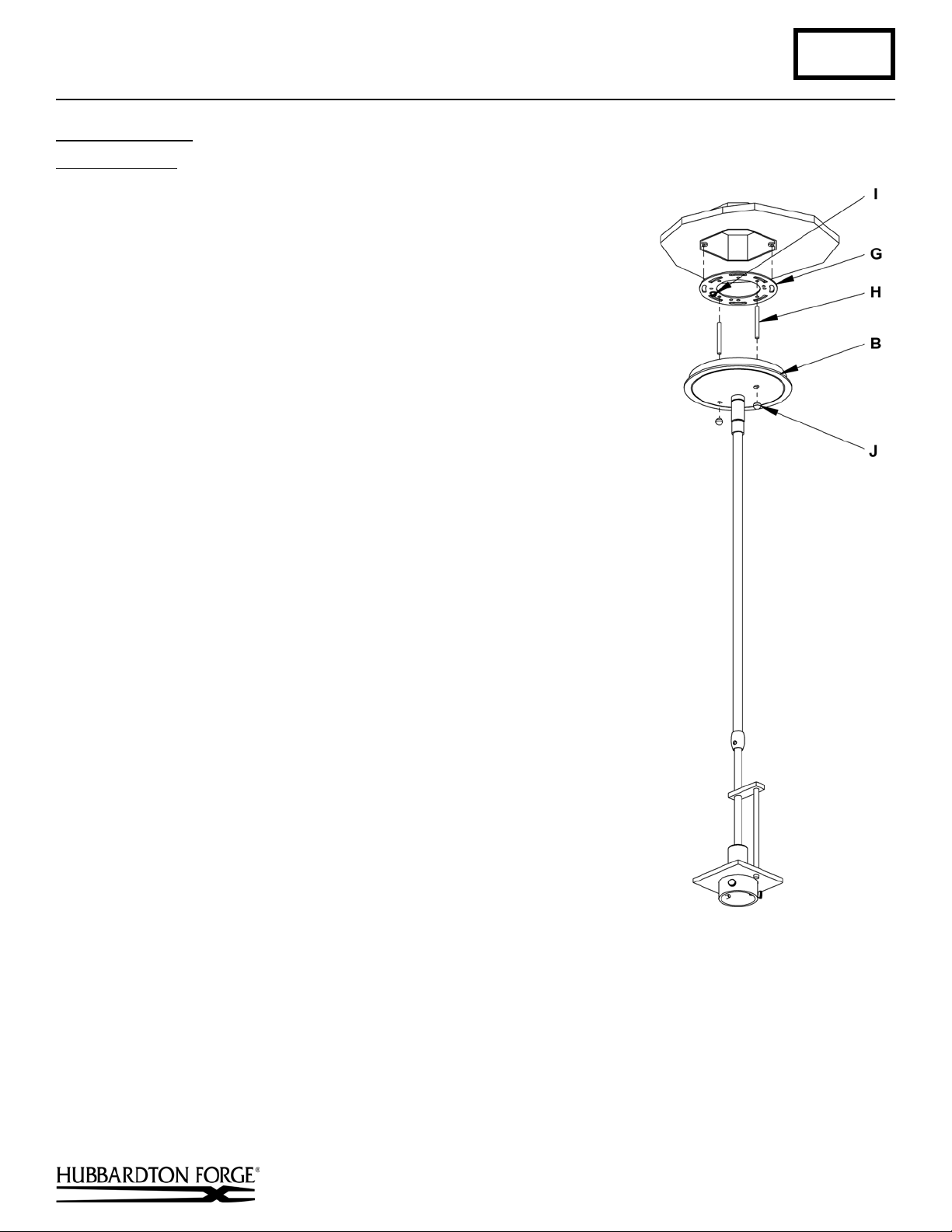
To Install Fixture (Figure 3)
Component Parts
B Canopy
G Crossbar
H Threaded stud (2)
I Ground screw
J Knurled Balls (2)
Caution: Be sure power is off at the main breaker box prior to installation.
1. Thread studs (H) through appropriate holes in the crossbar (G) to
match hole centers on canopy (B). Move ground screw (I) to
another available threaded hole if nece ssa ry .
2. Using two machine screws (not provided), fasten the crossbar (G)
to the electric box using outer oval slots to orient fixture to desired
hanging position.
Note: A new electric box comes with screws. When replacing a
fixture, retain the existing screws for use with the new fixture.
3. Using suitable wire connectors (not provided) connect fixture
wires to supply (white to white and black to black). Run a pigtail
lead from crossbar ground screw (I) to the junction box and
connect all ground wires (bare copper or green to bare copper or
green).
securely, and no bare wire is exposed.
4. Slide fixture canopy (B) with fixture attached, over threaded studs
(H) and push firmly to ceiling making sure that no wires are
pinched between fixture canopy and ceiling. Fasten with the
knurled balls (J). Be sure studs (H) are fully seated in the knurled
balls (J).
Note: For sloped ceilings the notch in the swivel should face
towards the down side.
Caution: Make sure wire connectors are twisted on
Hand-Forged, Vermont-Made Lighting and Accessories
154 Route 30 South, Castleton, Vermont 05735
26491
(continued)
Page 3

Assembly & Installation Instructions A275
(Figure 4)
Erlenmeyer Pendant 18-710 Page 3 of 3
To Install Glass (Figures 4)
Component Parts
K Bulb
L Glass
M Thumb Screw
1. Install bulb (K). Be careful not to touch bulb with bare hands; oil from
the hands will dramatically reduce bulb life.
2. Loosen the three thumb screws (M). It is not necessary to remove them
from the fixture.
3. Raise glass (L) until groove is aligned with thumb screws (M).
4. Tighten the three thumb screws (M) equal amounts until snug with
glass (L). Be careful not to over tighte n.
5. Restore electricity at main breaker.
If you need further assistance, or find that you are missing any parts, please contact the dealer from which you purchased
this product. We hope you enjoy your fixture!
* Hubbardton Forge will not be liable for injury or damage caused by improper installation, lamping or use of this fixture.
Hand-Forged, Vermont-Made Lighting and Accessories
154 Route 30 South, Castleton, Vermont 05735
26491
 Loading...