

Page 1
Assembly & Installation Instructions A327
CAUTION: FAILURE TO INSTALL THI S FIXTURE PROPERLY MAY RESULT I N SERIO US PERSO NAL
(Figure 1)
Apparatus Pendant 138801 Page 1 of 4
INJURY OR DEATH AND PROPERTY DAMAGE. We rec o mm e nd installation by a licensed electrician.
This product must be installed in accordance with applicable installation code(s), by a person familiar with the
construction and operation of the product and the hazards involved.*
Caution: Do not exceed maximum wattage noted on fixture. Use only recommended bulbs with fixture.
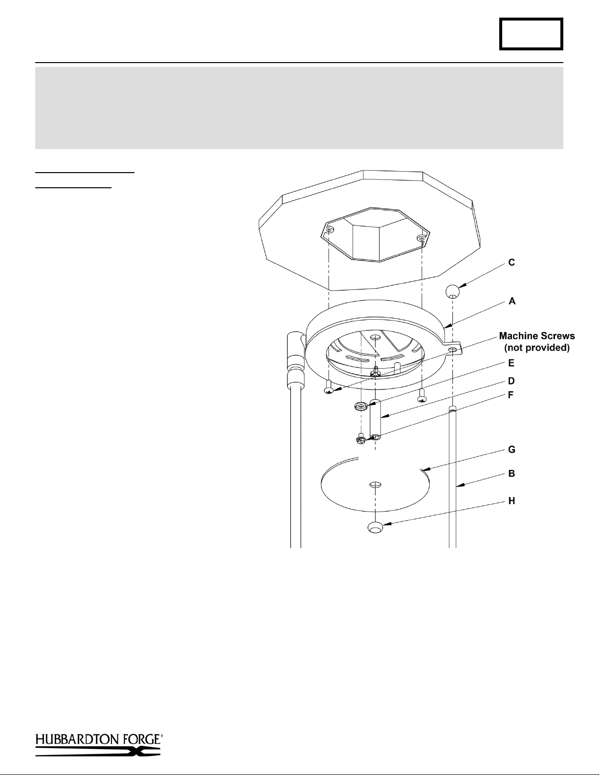
To Install to Ceiling (Figure 1)
Component Parts
A Fixture
B Rod
C Ball (2)
D Nipple
E Cupp ed was her
F Ground Screw
G Cover Plate
H Oval Nut
Caution: Be sure power is off at the
main breaker box prior to installation.
1. Carefully unpack the fixture from the
carton.
2. Remove ball (C) from one end of the
rod (B). Slide rod (B) through hole in
fixture (A) and replace ball (C ).
3. Thread wires from junction box
down through mounting plate on
fixture (A).
4. Raise fixture to ceiling aligning holes
in fixture (A) with holes in electric
box. Using two machine screws (not
provided) fasten the fixture (A) to the
electric box using outer oval slots to
orient fixture to desired hanging
position.
Note: A new electric box comes with
screws. When replacing an existing
fixture retain screws for use with the new
fixture.
5. Thread nipple (D) into center of mounting bracket on the fixture (A).
6. Using suitable wire connectors (not provided) connect fixture wires to supply (white to white and black to black).
Using cupped washer (E) and green ground screw (F) run pigtail from fixture (A) to junction box. Connect all
ground wires, bare copper or green to bare copper or green, including fixture ground wire. Push wires back into
fixture.
Caution: Make sure wire connectors are twisted on securely, and no bare wire is exposed.
7. Slip cover plate (G) over nipple (D) and secure using oval nut (H).
Hand-Forged, Vermont-Made Lighting and Accessories
154 Route 30 South, Castleton, Vermont 05735
28105
(continued)
Page 2
Assembly & Installation Instructions A327
(Figure 2)
Apparatus Pendant 138801 Page 2 of 4
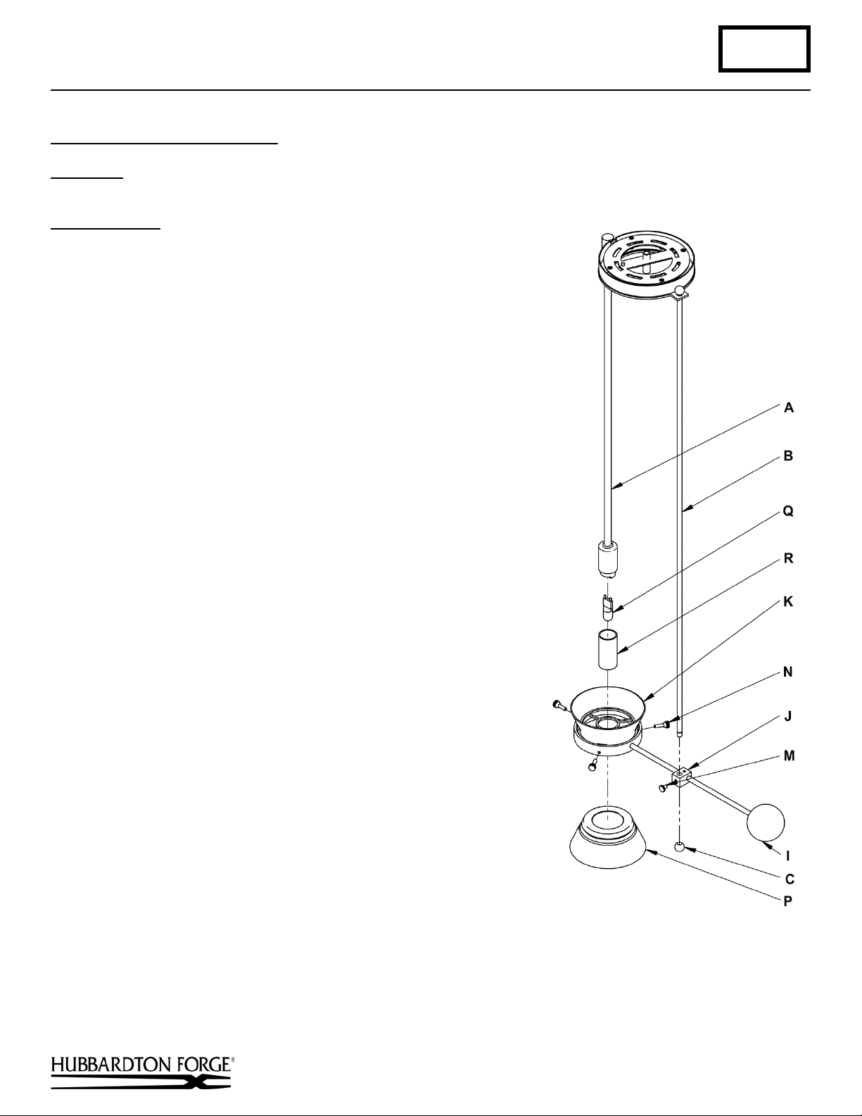
To Complete Fixture Assembly
OPTION 1: GLASS SIDE DOWN (Figure 2)
(For GLASS SIDE UP installation see next page)
Component Parts
A Fixture
B Rod
C Ball
I Counterweight
J Block
K Body
M Thumb Screw
N Thumb Screw (3)
P Glass
Q Bulb
R Shield
1. Install bulb (Q). Be careful not to touch bulb with bare hands; oil
from the hands will dramatically reduce bulb life.
2. Screw shield (R) on to socket. Do not over tighten.
Note: The fixture body (K) is factory shipped ready for installation
with glass side down. To reverse fixture and install with glass
side up, see To Complete Fixture Assembly –GLASS SIDE UP
(Figure 3) next page.
3. Loosen the three thumb screws (N). It is not necessary to remove
them from the fixture.
4. Raise glass (P) up into fixture body (K) and tighten thumb screws
(N) equally, until snug against glass.
5. Remove ball (C) from rod (B). Loosen Thumb screw (M) from
block (J). Slide fixture body (K) up on to rod (B), slipping the
fixture body (K) over the shield (R). Adjust to desired height and
tighten thumb screw (M).
6. Reattach ball (C) onto the rod (B)
7. Restore electricity at main breaker.
Hand-Forged, Vermont-Made Lighting and Accessories
154 Route 30 South, Castleton, Vermont 05735
28105
(continued)
Page 3

Assembly & Installation Instructions A327
(Figure 3)
Apparatus Pendant 138801 Page 3 of 4
To Complete Fixture Assembly
OPTION 2: GLASS SIDE UP (Figure 3)
Component Parts
A Fixture
B Rod
C Ball
I Counterweight.
J Block
K Body
L Set Screw
M Thumb Screw (short)
N Thumb Screw (3)
P Glass
Q Bulb
R Shield
1. Install bulb (Q). Be careful not to touch bulb with bare
hands; oil from the hands will dramatically reduce bulb
life.
2. Screw shield (R) on to socket. Do not over tighten.
3. To install fixtu re wi th the glas s sid e up, the orientation of
the block (J) must be changed (Figure 4). Set fixture body
(K) on a flat surface.
4. Loosen set screw (L). Carefully flip block (J) over. Make
sure that the block stays the same distance from the
counterweight (I) and glass (P). Make sure that the top of
the block is parallel to the top of the fixture body
(K).(Figure 4) Retighten set screw (L)
5. Loosen the three thumb screws (N). It is not necessary to
remove them from the fixture. (Figure 3)
6. Set glass (P) into fixture body (K) and tighten thumb
screws (N) equally, until snug against glass.
7. Remove ball (C) from rod (B). Loosen Thumb screw (M)
from block (J). Slide fixture body (K) up on to rod (B),
slipping the fixture body (K) over the shield (R). Adjust
to desired height and tighten thumb screw (M).
8. Reattach ball (C) onto the rod (B)
9. Restore electricity at main breaker.
Hand-Forged, Vermont-Made Lighting and Accessories
154 Route 30 South, Castleton, Vermont 05735
28105
(continued)
Page 4

Assembly & Installation Instructions A327
(Figure 4)
Apparatus Pendant 138801 Page 4 of 4
If you need further assistance, or find that you are missing any parts, please contact the dealer from which you purchased
this product. We hope you enjoy your fixture!
* Hubbardton Forge will not be liable for injury or damage caused by improper installation, lamping or use of this fixture.
Hand-Forged, Vermont-Made Lighting and Accessories
154 Route 30 South, Castleton, Vermont 05735
28105
 Loading...