

Page 1
Assembly & Installation Instructions A315
CAUTION: FAILURE TO INSTALL THI S FIXTURE PROPERLY MAY RESULT I N SERIO US PERSO NAL
Note
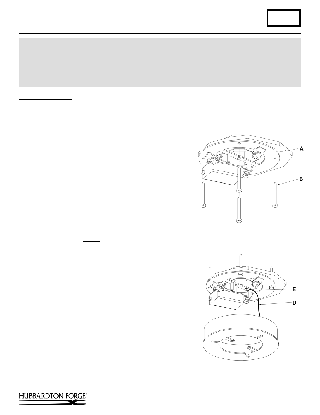
(Figure 1)
(Figure 2)
Aura LED Pendant 138587D Page 1 of 3
INJURY OR DEATH AND PROPERTY DAMAGE. We rec o mm e nd installation by a licensed electrician.
This product must be installed in accordance with applicable installation code(s), by a person familiar with the
construction and operation of the product and the hazards involved.*
Caution: Do not exceed maximum wattage noted on fixture. Use only recommended bulbs with fixture.
: Support Cable also acts as Low Voltage Supply Cable.
To Install to Ceiling (Figures 1 thru 5)
Component Part
A Ceiling Bracket
B Lag Screw (4)
C Canopy
D Canopy Support Cable
E #8 Screw
F Support/supply Cable (3)
Caution: Be sure power is off at the main breaker box prior to
installation.
1. Carefully unpack the fixture from the carton. Put the ceiling
bracket (A) and canopy (C) together, making sure the canopy
mounting holes match up with the ceiling bracket th rea ded
standoffs. Orient them to achieve desired wire location.
2. Using the four lag screws (B) attach ceiling bracket (A) to a
structural member in the ceiling, centering the crossbar over
the outlet box (Figure 1). Lag screws have been supplied with
your fixture; however, different materials and/or construction
methods may require different fasteners. If in doubt, contact a
qualified electrician. Do not attach crossbar directly to outlet
box.
3. Attach canopy support cable (D) to mounting bracket using a
#8 screw (E). Temporarily suspend canopy using cable
(Figure 2). #8 screw (E) ships installed, it will need to be
removed prior to installation of the support cable (D).
Caution: The cable is intended to temporarily suspend the
canopy to help with fixture installation. Ne ver dep end on
them to support fixture with glass installed.
4. Loosen cable gripper locks before try ing to install cabl es.
(Figure 3).
Note: Support cable (F) will not be able to pass through the
cable gripper (G) unless the locks are loose.
Hand-Forged, Vermont-Made Lighting and Accessories
P.O. Box 827, 154 Route 30 South, Castleton, Vermont 05735
G Cable Gripper (3)
H Flat Head Screws (2)
I Canopy Nipple
J Canopy Cover
K Cap
27760
(continued)
Page 2

Assembly & Installation Instructions A315
(Figure 3)
(Figure 4)
Aura LED Pendant 138587D Page 2 of 3
5. Raise fixture and push support cables (F) through
the canopy (C) and into the cable grippers (G )
until desired fixture height is accomplished and
level. Once desired height is accomplished and
product is level, tighten cable gripper locks.
(Figure 3).
6. Using heavy duty cable cutters, cut excess
supply/support cable (F) allowing enough left
(approx. 4”) to make connections. Locate support
cable (F) with a (+) label on the fix ture and slip
the red isolation sleeve (provided ) over the end.
Locate support cable (F) with a (-) label on the
fixture and slip the black isolation sleev e
(provided) over the end.
7. Using suitable wire connectors (provided) connect
support cable (F) with red isolation sleeve to red
driver wire with (+) label attached. Connect
support cable (F) with black isolation sleeve to
black driver wire with (-) label attached. Driver
wires will be shipped with connector attached.
Caution: Make sure wire connectors are on
securely, and no bare wire is exposed.
Note: If using the supplied closed end connector,
please use the MR30A crimping tool.
8. Remove canopy support cable (D) by removing #8 screw (E) from one end and #8 nut from other end (discard
cable).
9. Raise the canopy (C) to the ceiling and attach to ceiling bracket (A) with two flat head screws (H) (Figure 4).
Note: Flat head screws (H) will need to be removed from ceiling bracket (A) prior to installation of the canopy (C).
The screws are shipped installed
10. Using suitable wire connectors (not provided) connect
fixture wires to supply (white to white or ribbed, black to black
or smooth). Connect all ground wires.
Caution: Make sure wire connectors are twisted on securely,
and no bare wire is exposed.
11. Slip canopy cover (J) onto canopy nipple (I) (Figure 5, next
page).
12. Thread cap (K) on to canopy nipple (I). Tighten against canopy
cover (J) until snug
.
13. Refer to instructions following to install glass.
.
Hand-Forged, Vermont-Made Lighting and Accessories
P.O. Box 827, 154 Route 30 South, Castleton, Vermont 05735
(continued)
27760
Page 3

Assembly & Installation Instructions A315
(Figure 5)
(Figure 6)
Aura LED Pendant 138587D Page 3 of 3
Install Glass (Figure 6)
Component Parts
L Glass (6)
1. Slip glass (L) into slots in fixture between bulb locations.
2. Repeat for all six locations.
3. Restore electricity at the main breaker.
If you need further assistance, or find that you are missing any parts, please contact the dealer from which you purchased
this product. We hope you enjoy your fixture!
* Hubbardton Forge will not be liable for injury or damage caused by improper installation, lamping or use of this fixture.
Hand-Forged, Vermont-Made Lighting and Accessories
P.O. Box 827, 154 Route 30 South, Castleton, Vermont 05735
27760
 Loading...