

Page 1
Installation Instructions A92
g
(Fig
2
) (Fig
)
(Fig
)
Ondrian Pendant 13-8550 & 13-8552 Page 1 of 3
CAUTION: FAILURE TO INSTALL THIS FIXTURE PROPERLY MAY RESULT IN SERIOUS PERSONAL
INJURY OR DEATH AND PROPERTY DAMAGE. We recommend installation by a licensed electrician.
This product must be installed in accordance with applicable installation code(s), by a person familiar with the
construction and operation of the product and the hazards involved.*
Caution: Do not exceed maximum watta
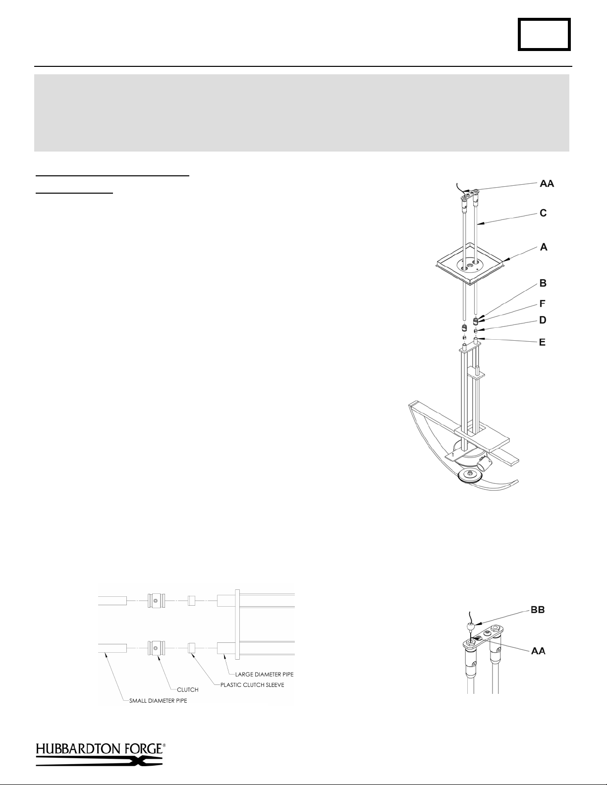
To Assemble Canopy & Pipes
Component Parts
A Canopy
B Clutch (2)
C Canopy Pipe (2)
D Plastic Clutch Sleeve (2)
E Fixture Pipe (2)
F Set Screw (2)
AA Support Cable
BB Cable Gripper
Caution: Be sure power is off at the main breaker box prior to
installation.
(Figures 1, 2 & 2A)
1. Carefully unpack the fixture from the carton.
2. Thread the wires and support cable (AA) from the fixture pipe (E)
up through the canopy (A), then into and through the canopy pipe
Note: Be sure to include the canopy in this step, or it will not
(C).
be possible to complete the installation. Note: Cable and wires
are in separate pipes.
3. Unscrew the clutch (B) from the fixture pipe and slide it across
the fixture wires and onto the canopy pipe (C). Follow this with
the clutch sleeve (D) so that the clutch sleeve nests in the clutch.
4. Slide the canopy pipe into the fixture pipe as far as necessary to
give the total fixture length desired. Be careful not to scratch the
pipes and to pull excess wire up through the canopy stem. There
must be a minimum of 1-1/2" of inner pipe inside the outer pipe.
Tighten the clutch onto the fixture pipe and secure by firmly
tightening the set screw (F).
be sure the tapered end of the plastic clutch sleeve is oriented toward the clutch when assembled (Figure 2).
5. Push support cable (AA) through cable gripper (BB) until cable is tight and has no slack. Once support cable is at
the correct height, excess cable behind the gripper can be cut off (Figure 2A).
Hand-Forged, Vermont-Made Lighting and Accessories
154 Route 30 South, Castleton, Vermont 05735
e noted on fixture. Use only recommended bulbs with fixture.
Important: To ensure full connection strength,
ure
19404 Rev B
ure 1
ure 2A
(continued)
Page 2
Installation Instructions A92
Ondrian Pendant 13-8550 & 13-8552 Page 2 of 3
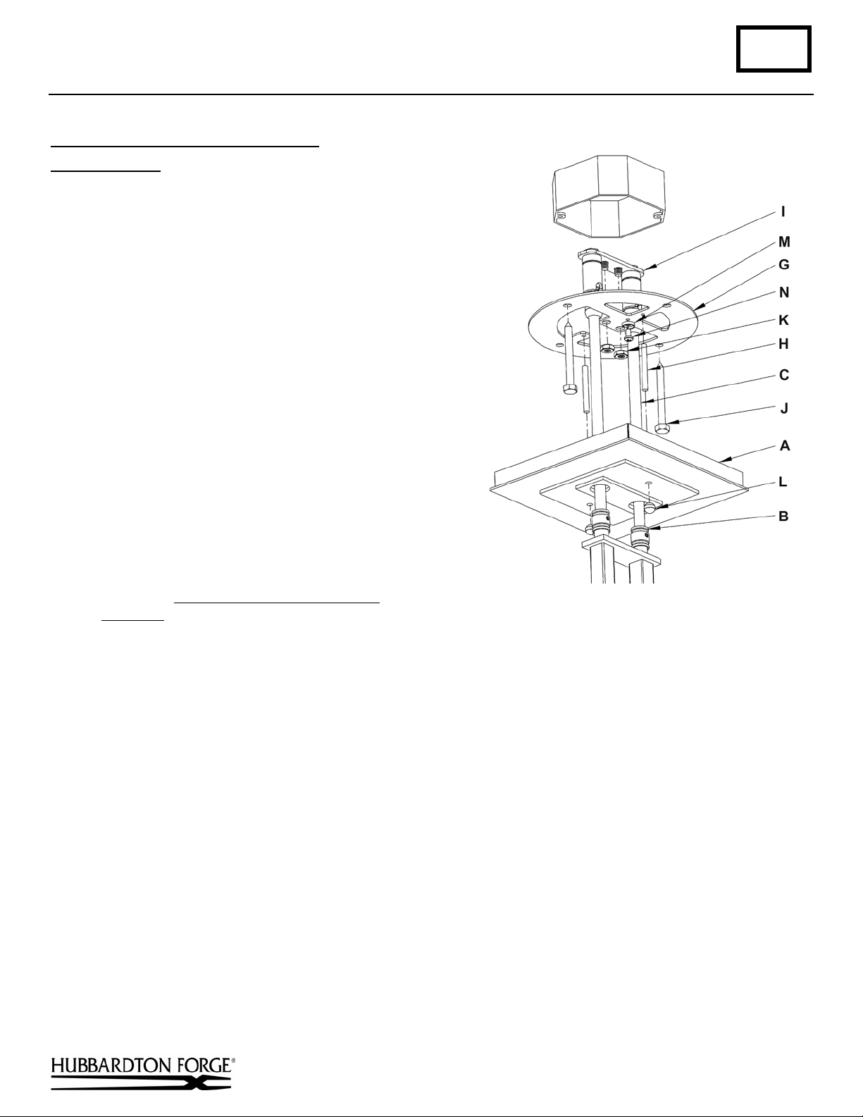
Complete Assembly & Install Fixture
Component Parts
A Canopy
B Clutch (2)
(Figure 3)
C Canopy Pipe (2)
G Crossbar
H Threaded Stud (2)
I Hanger Plate
J Lag Screw (4)
K 1/4-20 Nut (2)
L Knurl Ball (2)
M
Cupped Washer
Ground Screw
N
Caution: This fixture must be supported independently
of an outlet box.
Caution: Be sure power is off at the main breaker box
prior to installation.
1. Using at least two lag screws (J) attach cross bar
(G) to a structural member in the ceiling, centering
the crossbar over the outlet box. We've supplied lag
screws with your fixture; however, different
materials and/or construction methods may require
different fasteners. If in doubt, contact a qualified
electrician. Do not attach crossbar directly to
outlet box.
Figure 3
2. Push hanger plate (I) at top of assembled fixture
up into electrical box, past the crossbar then turn the hanger plate and drop the threaded studs in the hanger plate
into the larger inner holes in the crossbar. Make sure no wires are pinched. Secure with 1/4-20 nuts (K).
3. Using suitable wire connectors (not provided), connect fixture wires to supply wires (white or ribbed side of
fixture cord to white supply, black or smooth side of fixture cord to black supply, and bare copper to bare copper
or green supply). Ground the crossbar (G) using the green ground screw (N) and cupped washer (M) to secure a
pigtail lead to the bracket. Push wires back into outlet box.
securely, and no bare wire is exposed.
Caution: Make sure wire connectors are twisted on
4. Start the threaded studs (H) into the threaded holes in the crossbar to match holes in canopy (A).
5. Slide fixture canopy up over the threaded studs (H) and against ceiling. Secure with the two knurled balls (L).
6. Refer to instructions below to install glass and diffusers.
(continued)
Hand-Forged, Vermont-Made Lighting and Accessories
154 Route 30 South, Castleton, Vermont 05735
19404 Rev B
Page 3

Installation Instructions A92
For Ondrian Pendant 13-8550 & 13-8552 Page 3 of 3
To Install Glass
Component Parts
O Hex Nut
P Washer
Q Glass Bowl
R Cup with Foam Washer
S Threaded Nipple
1. Remove hex nut (O) and washer (P) from the
threaded nipple (S). Cup and foam washer (R) sit
loose on nipple (S), but do not require removal.
2. Place glass bowl (Q) over nipple and onto foam
washer (R).
3. Place washer (P) over nipple (S) followed by the hex
nut (O).
4. Position the glass and secure by hand tightening the
hex nut (O) (do not over tighten). For the best
appearance, the glass should be level with an even
gap between the glass and the curved bar on the
fixture.
5. Refer to diffuser installation instructions below to
complete the installation.
(Figure 4)
Figure 4
To Install Diffusers
Component Parts
T Diffuser Mounting Stud (2)
U Diffuser Glass (2)
V Washer (2)
W Knurled Ball Nuts (2)
(Figure 5)
1. Install light bulbs before installing
diffusers.
2. Place diffuser glass (U) over diffuser
mounting stud (T) with flat side of
diffuser glass toward center of the
fixture.
3. Place washer (V), over diffuser
mounting stud (T) and secure with
knurled ball nut (W).
4. Repeat for remaining diffuser glass.
5. Restore electricity at the main breaker.
Figure 5
If you need further assistance, or find that you are missing any parts, please contact the dealer from which you purchased
this product. We hope you enjoy your fixture!
* Hubbardton Forge will not be liable for injury or damage caused by improper installation, lamping or use of this fixture.
Hand-Forged, Vermont-Made Lighting and Accessories
154 Route 30 South, Castleton, Vermont 05735
19404 Rev B
 Loading...