

Page 1
Assembly & Installation Instructions A313
CAUTION: FAILURE TO INSTALL THI S FIXTURE PROPERLY MAY RESULT I N SERIO US PERSO NAL
(Figure 1)
Erlenmeyer Pendant 137725 Page 1 of 4
INJURY OR DEATH AND PROPERTY DAMAGE. We rec o mm e nd installation by a licensed electrician.
This product must be installed in accordance with applicable install ati on co de(s ), by a person familiar with the
construction and operation of the product and the hazards involved.*
Caution: Do not exceed maximum wattage noted on fixture. Use only recommended bulbs with fixture.
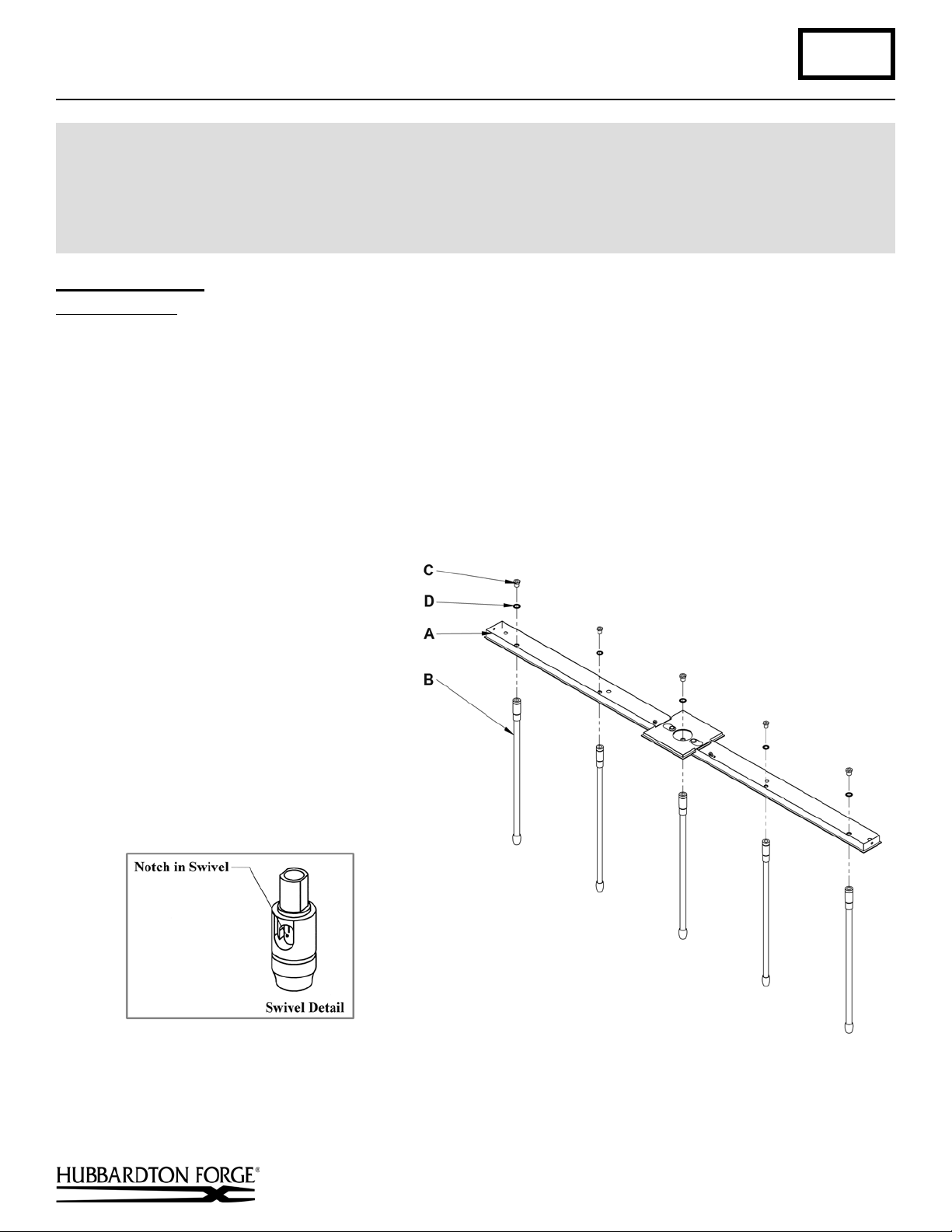
Assemble Canopy (Figure 1)
Component Parts
A Canopy
B Canopy Pipe
C Hex Nipple (5)
D Lock Washer (5)
1. Carefully unpack the fixture from the carton.
2. Insert threaded end of hex nipple (C) down through lock washer (D) and into swivel end of canopy pipe (B).
3. Tighten securely being sure the notches in the swivels are aligned (see swivel detail).
Note: If installing on a sloped ceiling, make certain that the notches in the swivel portion of the stems are oriented
toward the lowers side of the slope.
4.
Repeat steps for all five stems.
5.
Continue with attaching fixture pipes
below.
Hand-Forged, Vermont-Made Lighting and Accessories
154 Route 30 South, Castleton, Vermont 05735
27331
(continued)
Page 2
Assembly & Installation Instructions A313
(Figure 3)
(Figure 2)
(Figure 4)
Erlenmeyer Pendant 137725 Page 2 of 4
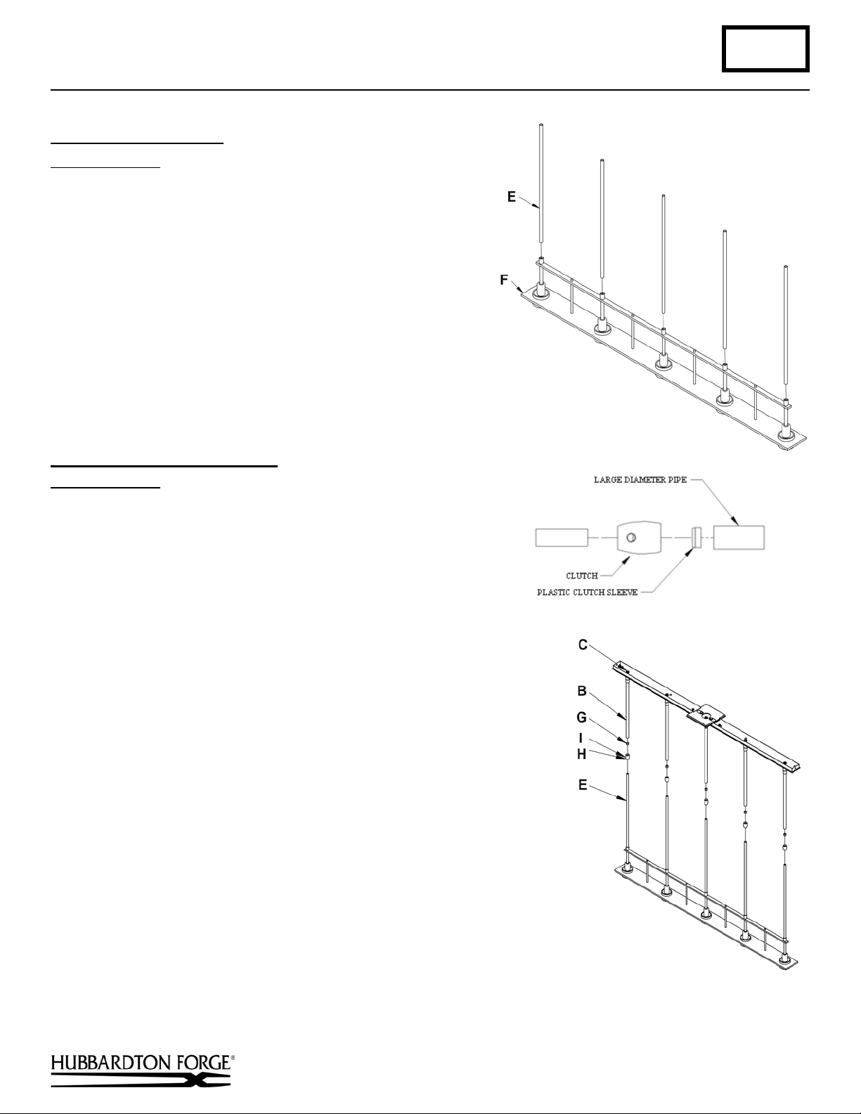
To Attach Fixture Pipes (Figure 2)
Component Parts
E Fixture Pipe (5)
F Fixture
1. Carefully thread fixture pipe (E), threaded end first, over
fixture wires.
2. Apply a drop of supplied thread locking compound to the
internal threads at the top of the fixture (F) and screw stem
into fixture, being careful not to twist wires.
Note: Application of the thread locking compound is
necessary to prevent the stem from loosening during regular
maintenance and cleaning of the fixture. Be sure to apply
the compound.
To Complete Fixture Assembly (Figures 3 & 4)
Component Parts
B Canopy Pipe (5)
E Fixture Pipe (5)
G Plastic Clutch Sleeve (5)
H Clutch (5)
I Set Screw (5)
1. Thread the wires from the fixture pipe (E) into and through the
canopy pipe (B) up through the hex nipple (C).
2. Unscrew the clutch (H) from the canopy pipe (B); slide it across the
wires and onto the fixture pipe (E). Follow this with the plastic
clutch sleeve (H), oriented so the tapered end of the clutch sleeve
nests in the clutch (Figure 3).
3. Slide the canopy pipe (B) as far as necessary to give you the total
length of the fixture which you desire. Be careful not to scratch the
pipe surfaces and to pull excess wire up through the canopy pipe (B).
Screw clutch (H) onto canopy pipe (B). There must be a minimum
1-1/2" of inner pipe inside the outer pipe. Hand-tighten the clutch to
temporarily hold this adjustment. The clutch is not securely fastened
at this point; do not depend on it to hold the fixture.
Important: To ensure full connection strength, be sure the tapered
end of the plastic clutch sleeve is oriented toward the clutch when
assembled and securely tighten set screw
(Figure 4).
4. Continue with ceiling installation below.
(continued)
Hand-Forged, Vermont-Made Lighting and Accessories
154 Route 30 South, Castleton, Vermont 05735
27331
Page 3

Assembly & Installation Instructions A313
(Figure 5)
Erlenmeyer Pendant 137725 Page 3 of 4
To Install to Ceiling (Figures 5 & 6)
Component Parts
A Canopy
J Mounting Bracket
K Anchor (2)
L #10 Scre w
M #8 Screw (3)
N Support Cable
O Cupped Washer
P Gr ound Scr e w
Q Threaded Stud
R Knurled Ball (2)
S Wire Connectors (2)
W Fixture Ground Wire
1. Thread studs (Q) through approp riate holes
in mounting bracket (J) to match holes in
canopy (A).
2. Position the mounting bracket (J) over the
electrical box aligning ovals in bracket with
mounting holes in electrical box. Orient
fixture to desired hanging position and mark
the location of both anchors (K) on the
ceiling. Set the mounting bracket aside.
3. Drill 1/8” holes in the location marked on
the ceiling. Place the tapered ends of both
anchors (2) into the holes and gently tap
flush with a hammer.
4. Place mounting bracket (J) over electrical
box. Using two machine screws (not
provided) fasten the mounting bracket (J) to
the electric box. Thread the #10 screws (L)
through the bracket and into the anchors to
secure the bracket to the ceiling. Be careful
not to over tighten or strip the anchors.
Note: A new electric box comes with screws. When replacing an existing fixture, retain screws for use with the new
fixture.
5. Using the two wire connectors (S) provided, connect four black fixture wires to one connector and four white fixture
wires to the other connector.
connectors (S) run a black pig tail lead and a white pig tail lead to the junction box. (Figure 6)
6. Check that fixture wires, ground wire (W), and cable (N) are routed up through the center hole in the square section of
the canopy.
7. Raise fixture close to ceiling. Attach support cable (N) to mounting bracket using a #8 screw. Temporarily suspend
fixture using cable.
Caution: The cable is intended to temporarily suspend fixture while wiring connections are completed. Never
depend on them to support fixtures with glass installed.
Wires should be stripped 3/8” maximum. In the remaining connection of the wire
(continued)
Hand-Forged, Vermont-Made Lighting and Accessories
154 Route 30 South, Castleton, Vermont 05735
27331
Page 4

Assembly & Installation Instructions A313
(Figure 6)
(Figure 7)
Erlenmeyer Pendant 137725 Page 4 of 4
8. Using suitable wire connectors (not provided) connect fixture wires to supply (white to white and black to black).
Using cupped washer (O) and green ground screw run pigtail from mounting bracket (J) to junction box. Connect all
ground wires, including fixture ground wire. Push wires back into outlet box.
Caution: Make sure wire connectors are twisted on securely, and no bare wire is exposed.
9. Raise fixture (F) to ceiling over threaded studs (Q) and push firmly to ceiling, making sure that no wires are pinched
between canopy and ceiling. Secure the canopy by attaching knurled balls (R) then threading #8 screws (M) through
the ends of the canopy into the threaded holes in the bracket (J).
Note: Be sure both swivel notches are aligned in the
same direction. For sloped ceilings the notches should
face towards the down side.
10. Once the fixture is fastened to the ceiling, tighten the
clutch set screws (I) firmly with hex wrench provided.
Only after the set screws (I) are tight should you install
the glass.
11. Continue with glass and bulb installation below.
To Install Glass (Figure 7)
Component Parts
T Bulb
U Glass
V Thumb Screw
1. Install bulb (T). Be careful not to touch bulb with bare hands; oil from the hands
will dramatically reduce bulb life.
2. Loosen the three thumb screws (V). It is not necessary to remove them from the
fixture.
3. Raise glass (U) until groove is aligned with thumb screws (V).
4. Tighten the three thumb screws (V) equal amounts until snug with glass (U).
Be careful not to over tighten.
5. Repeat steps 1 thru 4 for all five lights.
6. Restore electricity at main breaker.
If you need further assistance, or find that you are missing any parts, please contact the dealer from which you purchased
this product. We hope you enjoy your fixture!
* Hubbardton Forge will not be liable for injury or damage caused by improper installation, lamping or use of this fixture.
Hand-Forged, Vermont-Made Lighting and Accessories
154 Route 30 South, Castleton, Vermont 05735
27331
 Loading...