

Page 1

Assembly & Installation Instructions A256
For Current Pendant 13-7650 Page 1 of 3
CAUTION: FAILURE TO INSTALL THIS FIXTURE PROPERLY MAY RESULT IN SERIOUS PERSONAL
INJURY OR DEATH AND PROPERTY DAMAGE. We recommend installation by a licensed electrician.
This product must be installed in accordance with applicable installation code(s), by a person familiar with the
construction and operation of the product and the hazards involved.*
Caution: Do not exceed maximum wattage noted on fixture. Use only recommended bulbs with fixture.
To Install to Ceiling (Figures 1 thru 5)
Component Part
A Ceiling Bracket
B Cable Gripper (2)
C Gripper Nut (2)
D Canopy
E Support Cable (2)
F Fixture
Caution: Be sure power is off at the main breaker box prior to
installation.
1. Carefully unpack the fixture from the carton.
2. Using two machine screws (not provided),
fasten the ceiling bracket (A) to the electric
box.
Note: A new electric box comes with screws.
When replacing a fixture, retain the existing
screws for use with the new fixture.
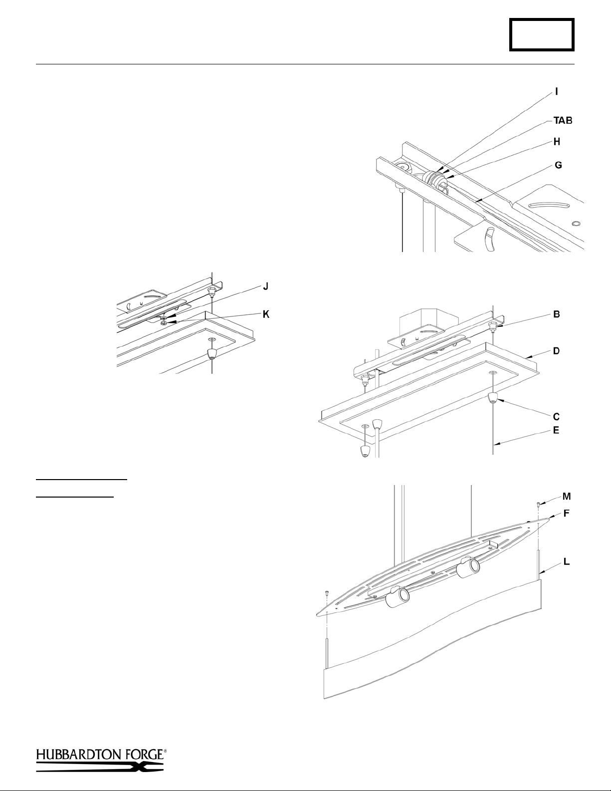
3. Slip gripper nuts (C) onto the support cables
(E) and allow to rest on top of fixture (F).
4. Pull support cables (E) and supply wire (G)
through canopy (D) allowing canopy to rest on
top of fixture (F).
5. Raise fixture and push support cables (E)
through cable grippers (B) until desired fixture
height is accomplished and level.
6. Slip supply wire (G) through strain relief (H)
and push supply wire (G) through slot on the
bottom of ceiling bracket (A) followed by
washer (I). Adjust location of strain relief (H)
on supply wire (G) until it will snap into
location provided on ceiling bracket (A).
7. Snap strain relief (H) onto supply wire (G) and
push into tab on ceiling bracket (Figure 3).
8. Once support cables are at the correct height, excess cable can be cut off. To keep the strands of cable together a
small piece of electrical tape can be applied to the cut end.
9. Cut excess supply wire (G) allowing enough left (approx. 6”) to make connections in the electrical box. Strip
outside jacket being careful not to cut through shielding of the two inner conductors.
G Supply wire
H Strain Relief
I Washer
J Cupped Washer
K Hex Nut
(Figure 1)
(Figure 2)
(continued)
Hand-Forged, Vermont-Made Lighting and Accessories
P.O. Box 827, 154 Route 30 South, Castleton, Vermont 05735
24786
Page 2
Assembly & Installation Instructions A256
For Current Pendant 13-7650 Page 2 of 3
10. Run a pigtail lead from the ceiling bracket (A) using cupped
washer (J) and hex nut (K) to the junction box. Using suitable wire
connectors (not provided) connect unshielded wire from supply
wire (I) to all ground wires (bare copper or green shielded)
(Figure 4).
11. Using suitable wire connectors (not provided) connect fixture
wires to supply (wire with white tracer to white and wire with no
tracer to black).
securely, and no bare wire is exposed.
12. Raise canopy (D) and push firmly to ceiling making sure that no
wires are pinched between fixture canopy and ceiling. Fasten to
ceiling by threading gripper nuts (C) onto grippers (B) (Figure 5).
Caution: Make sure wire connectors are twisted on
(Figure 3)
(Figure 4)
Fixture Assembly
Component Parts
F Fixture
L Center Plate Assembly
M 8-32 Screws (6)
N Outside Plate Assembly (2)
O Diffuser
P Shade
Q Thumb Screw with Washer and Hex Nut (2)
(Figures 6 thru 9)
1. Install two 8-32 screws (M) through the top of fixture
(F) and thread into center plate assembly (L) until
snug (Figure 6).
2. Install two 8-32 screws (M) through the top of fixture
(F) and thread into the first outside plate assembly
(N) until snug (Figure 7).
(Figure 5)
(Figure 6)
Hand-Forged, Vermont-Made Lighting and Accessories
P.O. Box 827, 154 Route 30 South, Castleton, Vermont 05735
(continued)
24786
Page 3

Assembly & Installation Instructions A256
For Current Pendant 13-7650 Page 3 of 3
3. Install diffuser (O) so it rests on top of center plate
assembly (L) and the notch is against the previously
installed outside plate assembly (N) (Figure 8).
4. Install two 8-32 screws (M) through the top of fixture
(F) and thread into the second outside plate assembly
(N) until snug (Figure 8).
5. Install Bulbs (not included).
6. Install shade (P) from the bottom and tilt so it will
pass fixture (F). Lower the shade so it rests on top of
the fixture.
7. Secure the shade (P) with the thumb screw, washer
and hex nut.
8. Restore electricity at the main breaker.
(Figure 7)
If you need further assistance, or find that you are missing
any parts, please contact the dealer from which you
purchased this product. We hope you enjoy your fixture!
* Hubbardton Forge will not be liable for injury or damage caused by improper installation, lamping or use of this fixture.
(Figure 8)
(Figure 9)
Hand-Forged, Vermont-Made Lighting and Accessories
P.O. Box 827, 154 Route 30 South, Castleton, Vermont 05735
24786
 Loading...