

Page 1
Assembly & Installation Instructions A218
For Exos Wave Large Five Light Pendant 13-7547 & 13-7547E Page 1 of 4
CAUTION: FAILURE TO INSTALL THIS FIXTURE PROPERLY MAY RESULT IN SERIOUS PERSONAL
INJURY OR DEATH AND PROPERTY DAMAGE. We recommend installation by a licensed electrician.
This product must be installed in accordance with applicable installation code(s), by a person familiar with the
construction and operation of the product and the hazards involved.*
Caution: Do not exceed maximum wattage noted on fixture. Use only recommended bulbs with fixture.
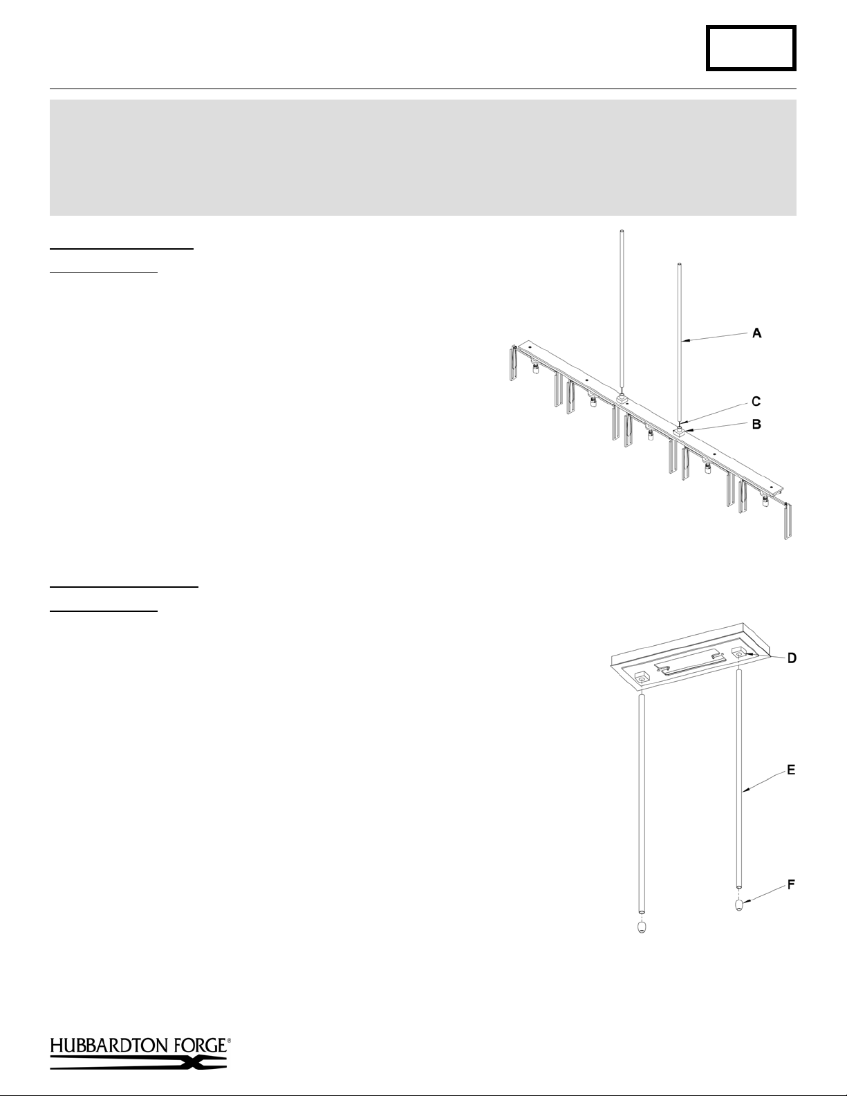
Install Fixture Pipes (Figure 1)
Component Parts
A Fixture Pipe (2)
B Fixture Coupling (2)
C Support Cable
1. Carefully unpack the fixture from the carton.
2. Carefully thread fixture pipe (A), threaded end first, over
fixture wires and support cable (C).
3. Apply a drop of the supplied thread locking compound to the
internal threads of fixture coupling (B) and screw pipe into
fixture, being careful not to twist or pinch the wires.
Note: Application of the thread locking compound is
necessary to prevent the stem from loosening during regular
maintenance and cleaning of the fixture. Be certain to apply
the compound.
4. See instructions following to complete the installation.
(Figure 1)
Install Canopy Pipes
Component Parts
D Canopy Coupling (2)
E Canopy Pipe (2)
(Figure 2)
F Decorative Caps (2)
1. Apply a drop of the supplied thread locking compound to the internal threads
of canopy coupling (D) and screw canopy pipe (E) into coupling.
Note: Application of the thread locking compound is necessary to prevent the
stem from loosening during regular maintenance and cleaning of the fixture.
Be certain to apply the compound.
2. Thread decorative caps (F) to bottom of canopy pipes (E).
3. See instructions following to complete the installation.
(Figure 2)
(continued)
Hand-Forged, Vermont-Made Lighting and Accessories
P.O. Box 827, 154 Route 30 South, Castleton, Vermont 05735
22897
Page 2
Assembly & Installation Instructions A218
For Exos Wave Large Five Light Pendant 13-7547 & 13-7547E Page 2 of 4
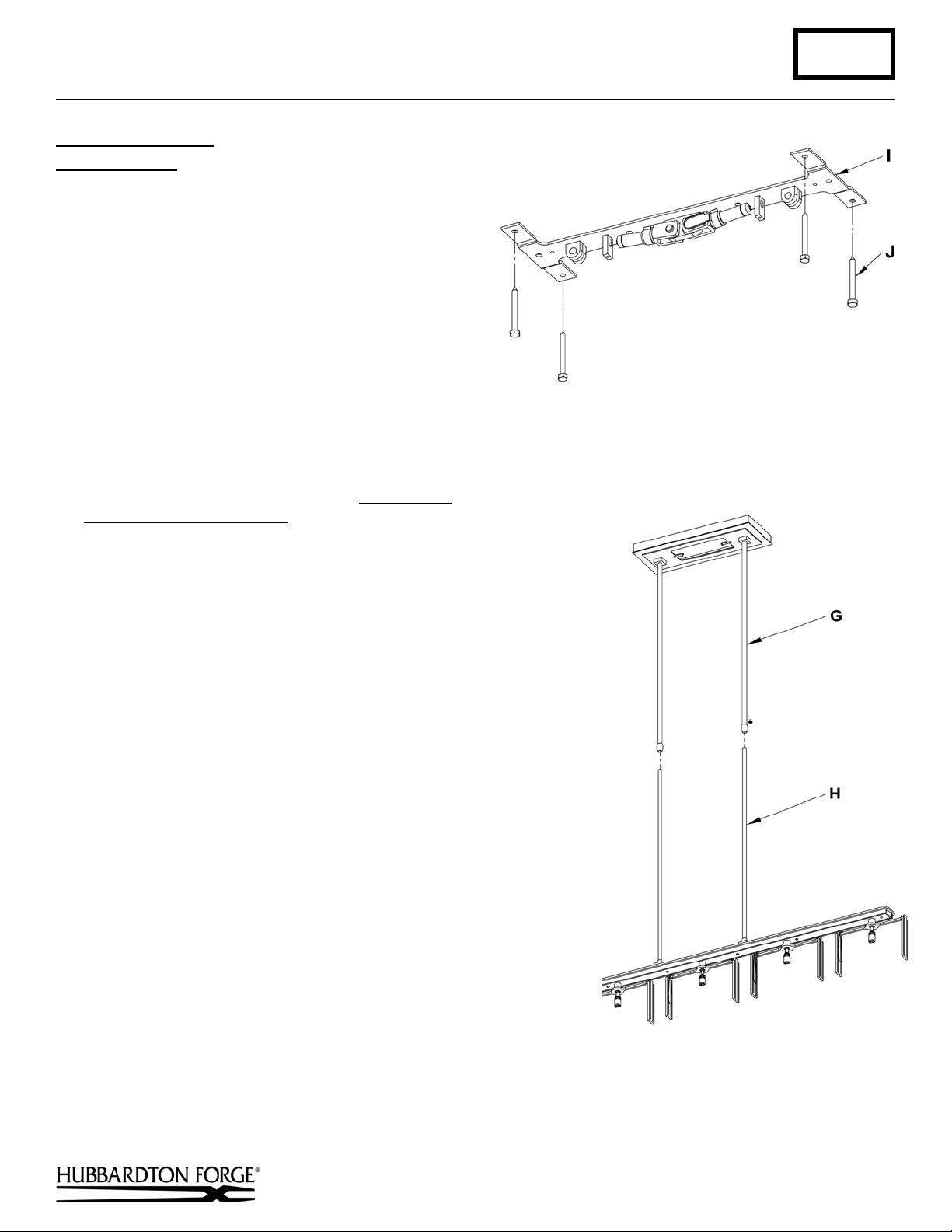
To Install to Ceiling
Component Parts
C Support Cable
G Canopy Assembly
H Fixture Assembly
I Ceiling Bracket
J Lag Screws (4)
K Cable Gripper
L Safety Nut
Caution: Be sure power is off at the main breaker
box prior to
installation.
1. Using four lag screws (J) attach ceiling bracket (I)
to a structural member in the ceiling, centering the
crossbar over the outlet box. We've supplied lag screws
with your fixture; however, different materials and/or
construction methods may require different fasteners. If
in doubt, contact a qualified electrician. Do not attach
crossbar directly to outlet box (Figure 3).
2. Thread wires and support cable (C) from the fixture assembly (H)
through the canopy assembly (G) (Figure 4).
3. Loosen both safety nuts (L) on cable grippers (K). It is not
necessary to completely remove them.
4. Raise fixture and push support cables (C) into cable grippers (K)
threading them through ceiling bracket (I) as shown in Figure 5 until
cables are tight and have no slack. Push cables through grippers
until desired fixture height is accomplished.
5. Raise canopy assembly (G) to ceiling making sure the fixture pipes
and canopy pipes over lap. Fasten to ceiling bracket (I) with flat
head screws (M) (Figure 5).
6. Once support cable is at the correct height, excess cable behind the
gripper can be cut off.
7. Tighten safety nuts (L).
8. Using suitable wire connectors (not provided) connect fixture wires
to supply (white to white and black to black, and bare copper to bare
copper or green supply). Ground the ceiling bracket (I) using the
green ground screw (P) and cupped washer (Q) to secure a pigtail
lead to the bracket. Push wires back into outlet box.
Caution: Make sure wire connectors are twisted on securely, and
no bare wire is exposed.
9. Install the wireway cover (N) and secure with barrel knobs (O)
(Figure 6).
10. Refer to instructions following to install glass.
(Figures 3 thru 6)
M Flat Head Screws
N Wireway Cover
O Barrel Knobs (2)
P Ground Screw
Q Cupped Washer
(Figure 3)
(Figure 4)
(continued)
Hand-Forged, Vermont-Made Lighting and Accessories
P.O. Box 827, 154 Route 30 South, Castleton, Vermont 05735
22897
Page 3

Assembly & Installation Instructions A218
For Exos Wave Large Five Light Pendant 13-7547 & 13-7547E Page 3 of 4
(Figure 6)
(Figure 5)
To Install Glass on G9 Version
Component Parts
R Metal Glass Clip (10)
S Glass Frame (5)
T Bulb (Included) (5)
U Bulb Shield (5)
V Glass (10)
(Figure 7)
1. Install light bulb (T). Be careful not to touch bulb
with bare hands. Oil from the hands will
dramatically reduce bulb life.
2. Thread bulb shield (U) onto socket. Future bulb
changes may be accomplished by snapping glass
bulb shield on and off rather than unthreading the
holder.
3. Turn glass frame (S) to make glass installation
easier.
4. Slide one side of glass (V) into slots in glass
frame (S). Metal glass clip (R) will push against
inside of glass to hold it in place.
5. Slide other side of glass (V) into glass frame (S).
6. Align the glass until it protrudes equal amounts on
both sides of fixture.
7. Turn glass frame (S) to desired angle.
(Figure 7)
(continued)
Hand-Forged, Vermont-Made Lighting and Accessories
P.O. Box 827, 154 Route 30 South, Castleton, Vermont 05735
22897
Page 4

Assembly & Installation Instructions A218
For Exos Wave Large Five Light Pendant 13-7547 & 13-7547E Page 4 of 4
To Install Glass on GU24 Version
Component Parts
R Metal Glass Clip (10)
S Glass Frame (5)
T Bulb (Included) (5)
V Glass (10)
1. Install light bulb (T).
2. Turn glass frame (S) to make glass installation
easier.
3. Slide one side of glass (V) into slots in glass
frame (S). Metal glass clip (R) will push against
inside of glass to hold it in place.
4. Slide other side of glass (V) into glass frame (S).
5. Align the glass until it protrudes equal amounts
on both sides of fixture.
6. Turn glass frame (S) to desired angle.
If you need further assistance, or find that you are missing any parts, please contact the dealer from which you purchased
this product. We hope you enjoy your fixture!
* Hubbardton Forge will not be liable for injury or damage caused by improper installation, lamping or use of this fixture.
(Figure 8)
(Figure 8)
Hand-Forged, Vermont-Made Lighting and Accessories
P.O. Box 827, 154 Route 30 South, Castleton, Vermont 05735
22897
 Loading...