

Page 1
Assembly & Installation Instructions A176
CAUTION: FAILURE TO INSTALL THI S FIXTURE PROPERLY MAY RESULT I N SERIO US PERSO NAL
(Figure 2)
(Figure 1)
Impressions Adjustable Pendant 13-6753 Page 1 of 3
INJURY OR DEATH AND PROPERTY DAMAGE. We rec o mm e nd installation by a licensed electrician.
This product must be installed in accordance with applicable installation code(s), by a person familiar with the
construction and operation of the product and the hazards involved.*
Caution: Do not exceed maximum wattage noted on fixture. Use only recommended bulbs with fixture.
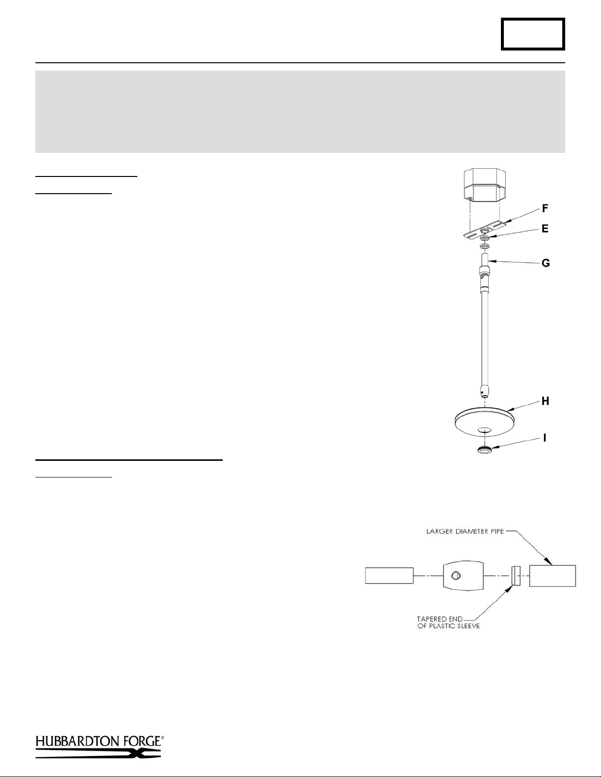
Prepare the Canopy (Figure 1)
Component Parts
E Jam Nut (2)
F Crossbar
G Threaded Nipple
H Canopy
I Canopy Ring
Caution: Be sure power is off at the main breaker box prior to installation.
1. Thread jam nuts (E) and crossbar (F) onto threaded nipple (G); leave parts loose.
2. Using two machine screws (not provided), temporarily fasten the crossbar (F) to the
electric box.
retain the existing screws for use with the new fixture.
3. Adjust the length of threaded nipp le (G ) in cros s bar (F ) so that canopy ring (I) will
hold canopy (H) against the ceiling with no threads showing for best appearance.
When the correct adjustment is established, tighten jam nuts (E) against crossbar (F)
to hold the adjustment.
4. Remove the crossbar and stem from the electrical box and proceed with the assembly
instructions.
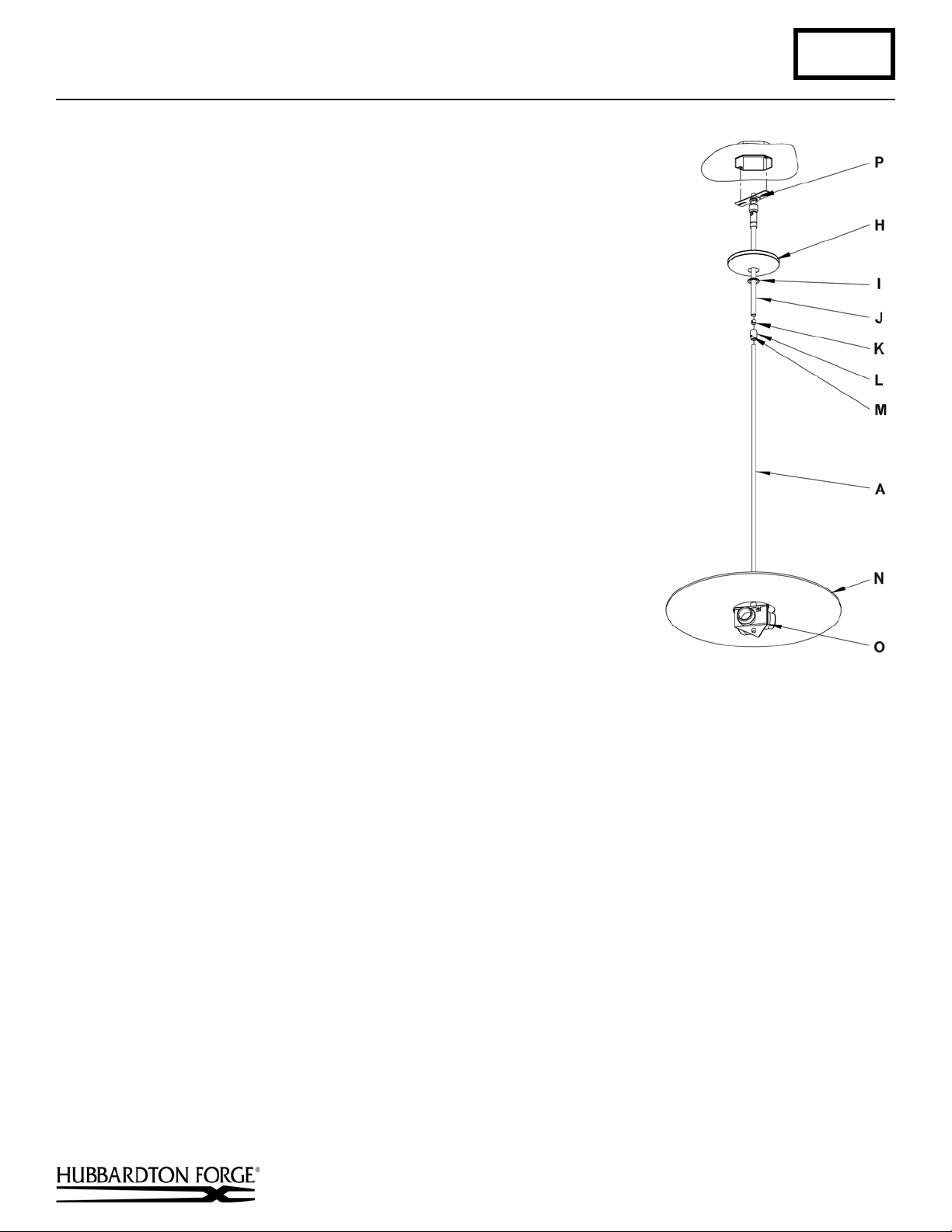
Complete Assembly & Install Fixture (Figures 2 & 3)
Note: A new electric box comes with screws. When replacing a fixture,
Component Parts
A Fixture Pipe
H Canopy
I Canopy Ring
J Canopy Pipe
K Plastic Sleeve
L Clutch
M Set Screw
N Top Diffuser
O Socket Assembly
P Ground Screw
Caution: Be sure power is off at the main breaker box prior to installation.
1. Place canopy (H) over canopy pipe (J), followed by canopy ring (I). Make
sure smaller diameter side of canopy ring is oriented up toward the canopy.
2. Slip diffuser (N) over fixture pipe (A) until it rests on top of socket assembly (O).
Hand-Forged, Vermont-Made Lighting and Accessories
154 Route 30 South, Castleton, Vermont 05735
21362 Rev C
(continued)
Page 2
Assembly & Installation Instructions A176
(Figure 3)
Impressions Adjustable Pendant 13-6753 Page 2 of 3
3. Thread wires from the fixture pipe (A) through the canopy pipe (J).
4. Unscrew the clutch (L) from the canopy pipe (J); slide it across the wires
and onto the fixture pipe (A). Follow this with the plastic clutch sleeve (K),
oriented so the tapered end of the clutch sleeve nests in the clutch
(Figure 3).
5. Slide the canopy pipe (J) as far as necessary to give you the total length of
the fixture which you desire. Be careful not to scratch the pipe surfaces and
to pull excess wire up through the canopy pipe (J). The re must be a
minimum 1-1/2" of inner pipe inside the outer pipe. Hand-tighten the
clutch to temporarily hold this adjustment. The clutch is not securely
fastened at this point; do not depend on it to hold the fixture.
Important: To ensure full connection strength, be sure the tapered end of
the plastic clutch sleeve is oriented toward the clutch when assembled and
securely tighten set screw (Figure 3).
6. Carefully slide canopy ring (I) and canopy (H) down over fixture pipe (A)
until they rest on the fixture.
7. Using two machine screws (not provided), fasten the crossbar to the
electric box.
Note: A new electric box comes with screws. When replacing a fixture,
retain the existing screws for use with the new fixture.
8. Using suitable wire connectors (not provided), connect fixture wires to
supply wires (white to white supply, black to black supply). Run a pigtail
lead from crossbar ground screw (P) to the junction box and connect all
ground wires (bare copper or green to bare copper or green). Push wires
back into outlet box.
Caution: Make sure wire connectors are twisted on securely, and no bare
wire is exposed.
9. Slide fixture canopy (H) against ceiling, and secure with canopy ring (I).
10. Once the fixture is fastened to the ceiling, tighten the set screw (M) firmly
with hex wrench provided. Only after the set screw (M) is tight should you install the glass.
11. Refer to instructions below to install glass and light bulb.
Hand-Forged, Vermont-Made Lighting and Accessories
154 Route 30 South, Castleton, Vermont 05735
21362 Rev C
(continued)
Page 3

Assembly & Installation Instructions A176
(Figure 4)
Impressions Adjustable Pendant 13-6753 Page 3 of 3
Install Glass (Figure 4)
Component Parts
N Top Diffuser
O Socket Assembly
Q Spider Assembly
R Thumb Screw (2)
S Glass
T Bottom Diffuser
1. Place glass (S) into notches of spider
assembly (Q).
2. Lift top diffuser (N) and place spider assembly
(Q) with glass (S) installed on top of socket
assembly (O).
3. Turn spider assembly (Q) so the holes match
the threaded holes in the socket assembly (O).
4. Install thumb screws (R).
5. Install light bulbs.
6. Insert the bottom diffuser (T) up into the
fixture at an angle then level it and gently
lower onto the lowest tabs of the spider assembly (Q).
7. Restore electricity at the main breaker.
If you need further assistance, or find that you are missing any parts, please contact the dealer from which you purchased
this product. We hope you enjoy your fixture!
* Hubbardton Forge will not be liable for injury or damage caused by improper installation, lamping or use of this fixture.
Hand-Forged, Vermont-Made Lighting and Accessories
154 Route 30 South, Castleton, Vermont 05735
21362 Rev C
 Loading...