

Page 1
Assembly & Installation Instructions A230
For Wren Five Light Pendant 13-6605 Page 1 of 4
CAUTION: FAILURE TO INSTALL THIS FIXTURE PROPERLY MAY RESULT IN SERIOUS PERSONAL
INJURY OR DEATH AND PROPERTY DAMAGE. We recommend installation by a licensed electrician.
This product must be installed in accordance with applicable installation code(s), by a person familiar with the
construction and operation of the product and the hazards involved.*
Caution: Do not exceed maximum wattage noted on fixture. Use only recommended bulbs with fixture.
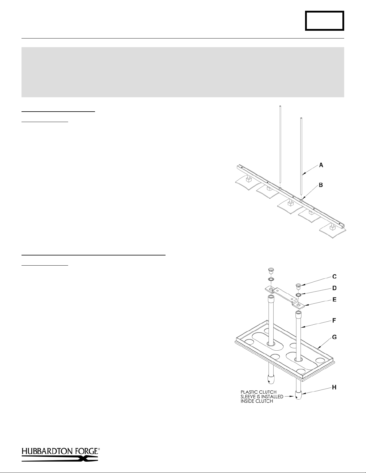
To Attach Fixture Pipes (Figure 1)
Component Parts
A Fixture Pipe (2)
B Fixture Coupling (2)
1. Carefully unpack the fixture from the carton.
2. Carefully thread fixture pipe (A), threaded end first, over fixture
wires.
3. Apply a drop of the supplied thread locking compound to the
internal threads at the top of the fixture (B) and screw stem into
fixture, being careful not to twist the wires.
Note: Application of the thread locking compound is necessary
to prevent the stem from loosening during regular maintenance
and cleaning of the fixture. Be certain to apply the compound.
4. See instructions below to complete the installation.
(Figure 1)
To Assemble Canopy Pipes to Ceiling Bracket
Component Parts
C Hex Nipple (2)
D Lock Washer (2)
E Ceiling Bracket
F Canopy Pipes (2)
G Canopy
H Clutch
(Figure 2)
1. Slip canopy pipes (F) through canopy (G).
2. Insert threaded end of hex nipple (C) down through lock
washer (D), ceiling bracket (E) and into threaded end of
canopy pipe (F) and tighten.
(Figure 2)
(continued)
Hand-Forged, Vermont-Made Lighting and Accessories
P.O. Box 827, 154 Route 30 South, Castleton, Vermont 05735
24158 Rev A
Page 2
Assembly & Installation Instructions A230
For Wren Five Light Pendant 13-6605 Page 2 of 4
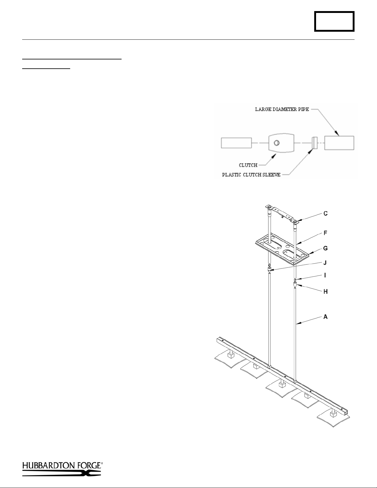
To Complete Fixture Assembly
Component Parts
A Fixture Pipe (2)
C Hex Nipple (2)
F Canopy Pipe (2)
G Canopy
Caution: Be sure power is off at the main breaker box
prior to installation.
(Figures 3 & 4)
H Clutch (2)
I Plastic Clutch Sleeve (2)
J Set Screw (2)
1. Slip canopy (G) over fixture pipes (A). Lower until
canopy (G) is resting on top of fixture. Be careful not to
scratch the pipe surfaces.
2. Run wires through canopy pipes (F) and out hex
nipples (C).
3. Unscrew the clutch (H) from the canopy pipe (F); slide it
across the wires and onto the fixture pipe (A). Follow this
with the plastic clutch sleeve (I), oriented so the tapered
end of the clutch sleeve nests in the clutch (Figure 3).
4. Slide the canopy pipe (F) as far as necessary to give you
the total length of the fixture which you desire. Be
careful not to scratch the pipe surfaces and to pull
excess wire up through the canopy pipe (F). Screw
clutch (H) onto canopy pipe (F). There must be a
minimum 1-1/2" of inner pipe inside the outer pipe.
Hand-tighten the clutch to temporarily hold this
adjustment. The clutch is not securely fastened at this
point; do not depend on it to hold the fixture.
Important: To ensure full connection strength, be sure
the tapered end of the plastic clutch sleeve is oriented
toward the clutch when assembled and securely tighten
set screw (Figure 3).
5. Continue with Ceiling Installation.
(Figure 3)
(Figure 4)
(continued)
Hand-Forged, Vermont-Made Lighting and Accessories
P.O. Box 827, 154 Route 30 South, Castleton, Vermont 05735
24158 Rev A
Page 3

Assembly & Installation Instructions A230
For Wren Five Light Pendant 13-6605 Page 3 of 4
To Install to Ceiling
Component Parts
E Ceiling Bracket
G Canopy
J Set Screw (2)
K Crossbar
L Stud (2)
1. Thread studs (N) through appropriate holes in
crossbar (K) to match holes in canopy (G).
2. Using two machine screws (not provided) fasten
cross bar (K) to the electric box using tab holes to
orient fixture to desired hanging position.
new electric box comes with screws. When
replacing an existing fixture, retain the screws for
use with the new fixture.
Alternate Mounting Option - Using four lag screws
(M) attach crossbar (K) to a structural member in
the ceiling, centering the crossbar over the outlet
box. We've supplied lag screws with your fixture;
however, different materials and/or construction
methods may require different fasteners. If in doubt,
contact a qualified electrician.
3. Raise fixture to ceiling aligning studs in crossbar
(K) with holes in ceiling bracket (E).
4. Thread hex nut (O) onto studs (L) and tighten.
5. Using suitable wire connectors (not provided)
connect fixture wires to supply (white to white and
black to black, and bare copper to bare copper or
green supply). Push wires back into outlet box.
Caution: Make sure wire connectors are twisted on
securely, and no bare wire is exposed.
6. Raise canopy (G) to ceiling over threaded studs (N)
and push firmly to ceiling, making sure that no wires
are pinched between canopy and ceiling. Fasten with
barrel knob (P).
Note: Be sure both swivel notches are aligned in the same direction. For sloped ceilings the notches should face
towards the down side.
7. Once the fixture is fastened to the ceiling, tighten the set screw (J) firmly with hex wrench provided. Only after the
set screw (J) is tight should you install the glass.
8. Refer to instructions below to install glass.
(Figure 5)
M Lag Screw (4)
N Threaded Stud (2)
O Hex Nut (2)
P Barrel Knob (2)
Note: A
(Figure 5)
Hand-Forged, Vermont-Made Lighting and Accessories
P.O. Box 827, 154 Route 30 South, Castleton, Vermont 05735
(continued)
24158 Rev A
Page 4

Assembly & Installation Instructions A230
For Wren Five Light Pendant 13-6605 Page 4 of 4
To Install Glass with G9 Option
Component Parts
Q Glass (5)
R Socket (5)
S Bulb (Included) (5)
T Bulb Shield (5)
U Spacer (5)
(Figure 6)
1. Install light bulb (S). Be careful not to touch bulb with bare hands; oil from the
hands will dramatically reduce bulb life.
2. Slip glass (Q) over socket (R).
3. Place spacer (U) on bulb shield (T) (note orientation of spacer).
4. Thread bulb shield (T) onto socket (R) (be careful not to over tighten). Future
bulb changes may be accomplished by snapping glass portion of barrier on and
off rather than unthreading the holder.
5. Restore electricity at main breaker.
To Install Double Glass with G9 Option
Component Parts
Q Glass (5)
R Socket (5)
S Bulb (Included) (5)
T Bulb Shield (5)
U Spacer (5)
V Inner Glass (5)
W Retaining Ring (5)
X Retaining Ring Tool
(Figure 7)
1. Install light bulb (S). Be careful not to touch bulb with bare hands; oil from the hands
will dramatically reduce bulb life.
2. Slip glass (Q), inner glass (V) & spacer (U) (note orientation of spacer) over
socket (R).
3. Thread retaining ring (W) onto socket (R) using provided retaining ring tool (X).
4. Thread bulb shield (T) onto socket (R) (be careful not to over tighten). Future bulb
changes may be accomplished by snapping glass portion of barrier on and off rather
than unthreading the holder.
5. Restore electricity at main breaker.
(Figure 6)
(Figure 7)
If you need further assistance, or find that you are missing any parts, please contact the
dealer from which you purchased this product. We hope you enjoy your fixture!
* Hubbardton Forge will not be liable for injury or damage caused by improper installation, lamping or use of this fixture.
Hand-Forged, Vermont-Made Lighting and Accessories
P.O. Box 827, 154 Route 30 South, Castleton, Vermont 05735
24158 Rev A
 Loading...