

Page 1
Assembly & Installation Instructions A235
For Axis Pendant 13-6403 & 13-6403F Page 1 of 4
CAUTION: FAILURE TO INSTALL THIS FIXTURE PROPERLY MAY RESULT IN SERIOUS PERSONAL
INJURY OR DEATH AND PROPERTY DAMAGE. We recommend installation by a licensed electrician.
This product must be installed in accordance with applicable installation code(s), by a person familiar with the
construction and operation of the product and the hazards involved.*
Caution: Do not exceed maximum wattage noted on fixture. Use only recommended bulbs with fixture.
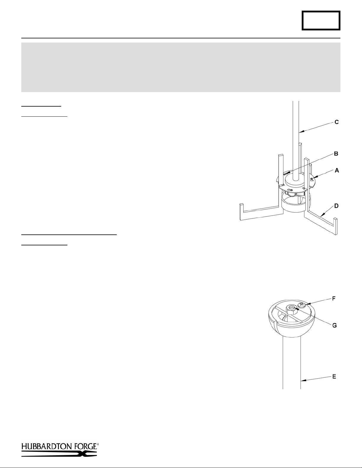
Disassemble (Figure 1)
Component Parts
A Screws (3)
B Locking Screw
C Upper Assembly
D Lower Assembly
1. Carefully unpack the fixture from the carton.
2. Remove locking screw (B) from upper assembly (C).
3. Loosen the three screws (A) remaining. It is not necessary to totally
remove them.
4. Turn lower assembly (D) counter clockwise until both assemblies
come apart. Save all parts for later use.
To Complete Fixture Assembly
Component Parts
C Upper Assembly
E Canopy Pipe Assembly
F 8-32 Screw
G Cable Gripper Assembly
H Canopy
I Aircraft Cable
J Top Diffuser
K Cable Gripper
Caution: Be sure power is off at the main breaker box prior to installation.
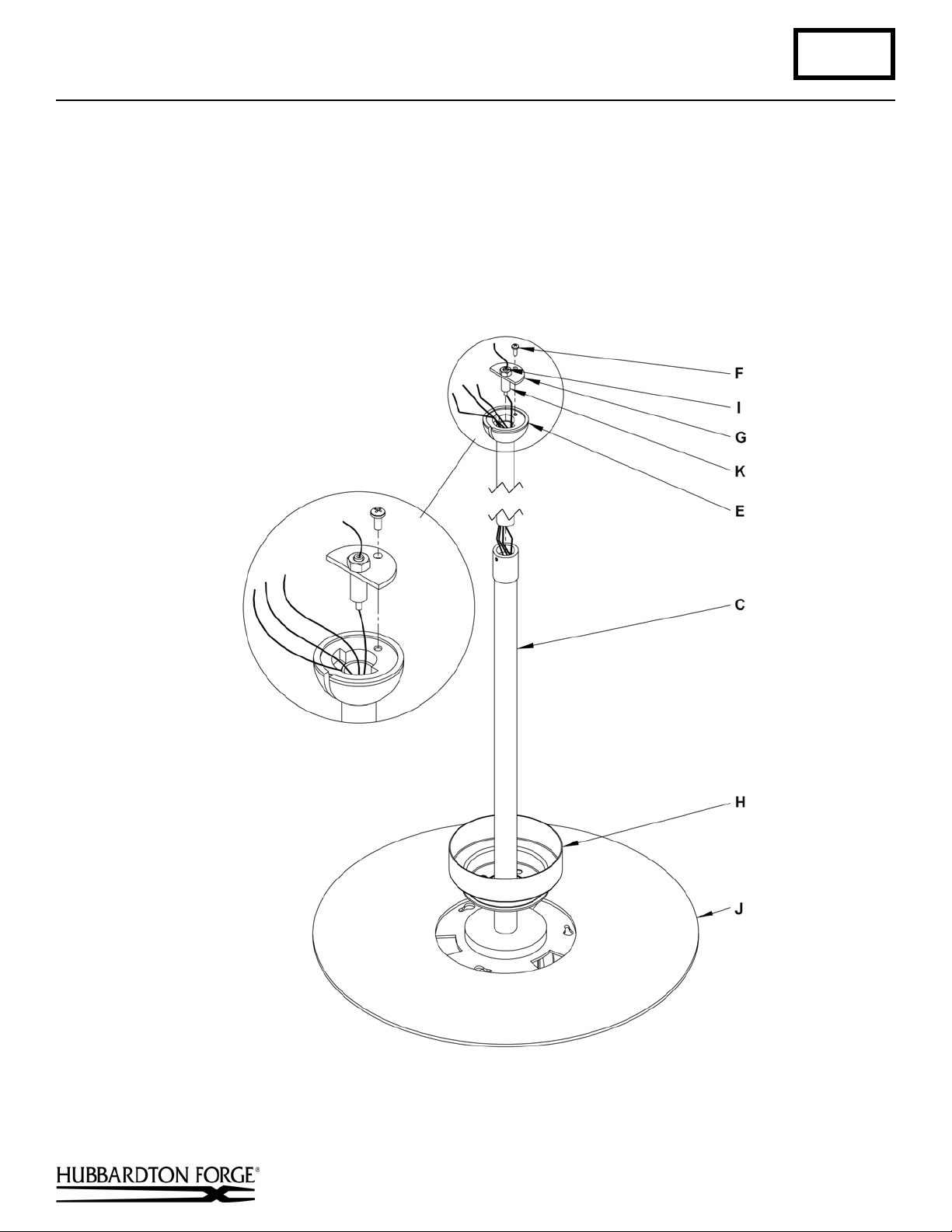
(Figures 2 & 3)
1. Remove 8-32 screw (F) and save for later use.
2. Lift cable gripper assembly (G) from canopy pipe assembly (E) (Figure 2).
3. Slip top diffuser (J) onto upper assembly (C) until it rests above sockets.
4. Slip wires and aircraft cable (I) through hole in the bottom of canopy (H).
5. Slip canopy (H) onto upper assembly (C) and allow it to rest on top of fixture.
6. Thread the wires and aircraft cable (I) from the upper assembly (C) into and
through the canopy pipe assembly (E).
7. Lower canopy pipe assembly (E) into upper assembly (C) until it bottoms out.
(Figure 1)
(Figure 2)
(continued)
Hand-Forged, Vermont-Made Lighting and Accessories
P.O. Box 827, 154 Route 30 South, Castleton, Vermont 05735
24159
Page 2
Assembly & Installation Instructions A235
For Axis Pendant 13-6403 & 13-6403F Page 2 of 4
8. Push the aircraft cable (I) through the bottom of the cable gripper (K). Do not pull the aircraft cable completely
through at this point.
9. Slip canopy pipe assembly (E) up to desired height while pulling the aircraft cable (I) through the cable gripper (K).
Measurement equals from ceiling to desired location of fixture bottom subtract 5 1/8”. (If total length equals 40”
subtract 5 1/8” from 40” and this is the measurement to set the canopy pipe assembly to).
10. Attach cable gripper assembly (G) to canopy pipe assembly (E) using 8-32 screw (F).
11. Pull excess aircraft cable (I) through cable gripper (K) until snug.
(Figure 3)
(continued)
Hand-Forged, Vermont-Made Lighting and Accessories
P.O. Box 827, 154 Route 30 South, Castleton, Vermont 05735
24159
Page 3

Assembly & Installation Instructions A235
For Axis Pendant 13-6403 & 13-6403F Page 3 of 4
Install Fixture to Ceiling
Component Parts
E Canopy Pipe Assembly
H Canopy
L Crossbar
M Ground Screw
N Threaded Studs (2)
O Barrel Knobs (2)
1.
Using two machine screws (not provided), fasten the crossbar (L) to
the electric box using oval slots to orient fixture to desired hanging
position. We've supplied lag screws with your fixture; however,
different materials and/or construction methods may require
different fasteners. If in doubt, contact a qualified electrician.
Note: A new electric box comes with screws. When replacing a
fixture, retain the existing screws for use with the new fixture.
2. Thread studs (N) through appropriate holes in the crossbar (L) to
match hole centers on canopy (H).
3. Using suitable wire connectors (not provided) connect fixture wires
(Figure 4)
to supply (white to white or ribbed and black to black or smooth).
4. Lift canopy (H) and connect all ground wires to green ground
(Figure 4)
screw (M).
5. Slide canopy (H) over threaded studs (N) and push firmly to ceiling, making sure that no wires are pinched between
fixture canopy and ceiling. Fasten with barrel knobs (O). Be sure studs are fully seated in the barrel knobs.
6. Refer instructions following to install bulb and glass.
To Install Glass in Bottom Assembly
Component Parts
D Lower Assembly
P Center Diffuser
Q Bottom Diffuser
R Outer Glass
(Figure 5)
1. Install center diffuser (P) so it sits in the center of the lower assembly (D).
2. Install bottom diffuser (Q) and outer glass (R) into lower assembly (D).
Hand-Forged, Vermont-Made Lighting and Accessories
P.O. Box 827, 154 Route 30 South, Castleton, Vermont 05735
(Figure 5)
(continued)
24159
Page 4

Assembly & Installation Instructions A235
For Axis Pendant 13-6403 & 13-6403F Page 4 of 4
To Install Bulbs and Bottom Assembly
Component Parts
A Screws (3)
B Locking Screw
C Upper Assembly
D Lower Assembly
1. Install light bulbs. “F” version bulbs are included.
2. Raise lower assembly (D) with glass installed so vertical bars
pass through openings in the upper assembly (C) and screws (A)
pass through the larger end of the three slots.
3. Turn lower assembly (D) until it stops in the locked position.
4. Tighten the three screws (A).
5. Install and tighten locking screw (B).
6. Restore electricity at the main breaker.
If you need further assistance, or find that you are missing any parts, please contact the dealer from which you purchased
this product. We hope you enjoy your fixture!
* Hubbardton Forge will not be liable for injury or damage caused by improper installation, lamping or use of this fixture.
(Figure 6)
(Figure 6)
Hand-Forged, Vermont-Made Lighting and Accessories
P.O. Box 827, 154 Route 30 South, Castleton, Vermont 05735
24159
 Loading...