

Page 1
Assembly & Installation Instructions A309
CAUTION: FAILURE TO INSTALL THI S FIXTURE PROPERLY MAY RESULT I N SERIO US PERSO NAL
(Figure 1)
(Figure 2)
Icarus Triple Canopy Pendant 13-3360 Page 1 of 4
INJURY OR DEATH AND PROPERTY DAMAGE. We recommend installation by a licensed electrician.
This product must be installed in accordance with applicable installation code(s), by a person familiar with the
construction and operation of the product and the hazards involved.*
Caution: Do not exceed maximum wattage noted on fixture. Use only recommended bulbs with fixture.
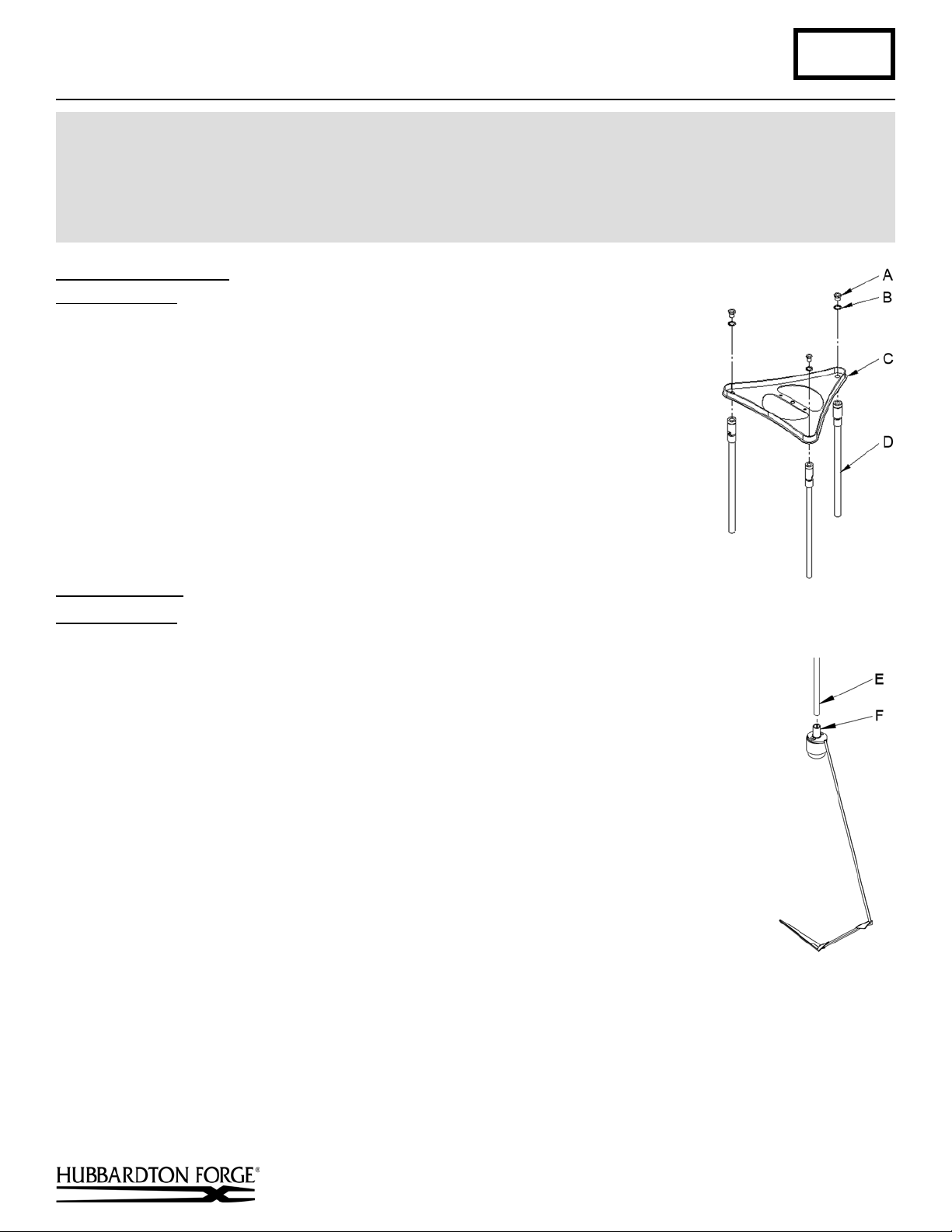
To Assemble Canopy (Figure 1)
Component Parts
A Hex Nipple (3)
B Lock Washer (3)
C Canopy
D Canopy Pipe (3)
1. Carefully unpack canopy from carton.
2. Line up end of canopy pipe (D) with hole in canopy (C).
3. Place hex nipple (A) through lock washer (B), down through holes in canopy and
thread into canopy pipe. Tighten securely.
4. Repeat steps 2 and 3 for the remaining stems.
Stem Assembly (Figure 2)
Component Parts
E Fixture Pipe (3)
F Fixture Coupling (3)
1. Carefully unpack the fixture from the carton.
2. Carefully thread fixture pipe (E), threaded end first, over fixture wires.
3. Apply a drop of the supplied thread locking compound to the internal thr eads of
fixture coupling (F) and screw stem into fixture, being careful not to twist or pinch the
wires.
Note: Application of the thread locking compound is necessary to prevent the stem
from loosening during regular maintenance and cleaning of the fixture. Be certain to
apply the compound.
4. Repeat for all three fixtur es .
5. See instructions below to complete the installation.
(continued)
Hand-Forged, Vermont-Made Lighting and Accessories
154 Route 30 South, Castleton, Vermont 05735
27236A
Page 2
Assembly & Installation Instructions A309
(Figure 4)
(Figure 3)
Icarus Triple Canopy Pendant 13-3360 Page 2 of 4
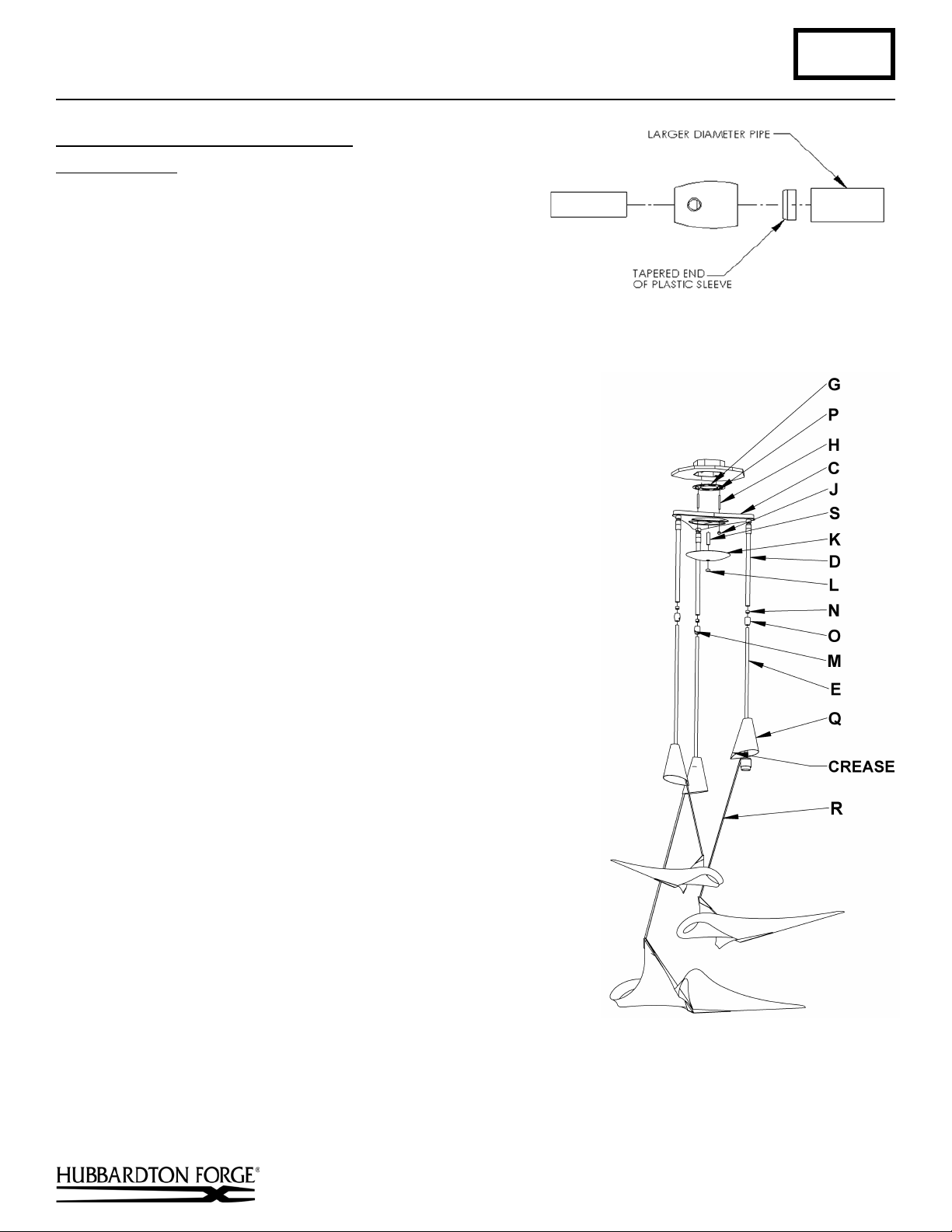
Complete Assembly & Install Fixture (Figures 3 & 4)
Component Parts
C Canopy
D Canopy Pipe (3)
E Fixture Pipe (3)
G Crossbar
H Threaded Studs (2)
J Knurl Ball (2)
K Canopy Cover
L Lock Up
M Set Screw (3)
N Clutch Sleeve (3)
O Clutch (3)
P Ground Screw
Q Bulb Shade (3)
R Fixture Frame (3)
S Canopy Nipple
Caution: Be sure power is off at the main breaker box prior to installation.
1. Slip bulb shade (Q) on fixture pipe (E) and orient so the crease slips onto the
bar of the fixture frame (R).
2. Thread the wires from the fixture pipe (E) into and through the canopy pipe
(D) up through the canopy (I).
3. Unscrew the clutch (O) from the canopy pipe (D) slide it across the wires
and onto the fixture pipe (E). Follow this with the clutch sleeve (N), so it
nests in the clutch (O).
4. Slide the fixture pipe (E) up into canopy pipe (D) as far necessary to give
you the total length of the fixture which you desire. Be careful not to scratch
the pipe surfaces and to pull excess wire up through the canopy (C). There
must be a minimum 1-1/2" of inner pipe inside the outer pipe. Handtighten the clutch to temporarily hold this adjustment. At this point the
adjustment is not securely fastened; do not depend on it to hold the
fixture.
Important: To ensure full connection strength, be sure the tapered end
of the plastic clutch sleeve is oriented toward the clutch when assembled
and securely tighten set screw
5. Repeat steps 1 thru 4 for all fixtures.
6. Thread studs (H) through appropriate holes in the crossbar (G) to match hole
centers in canopy (C).
7. Using two machine screws (not provided), fasten the crossbar (G) to the
electric box using outer oval slots to orient fixture to desired hanging
position.
fixture, retain the existing screws for use with the new fixture.
Note: A new electric box comes with screws. When replacing a
8. Slide fixture canopy (C) with fixture attached, over threaded studs (H) and push
firmly to ceiling making sure no wires are pinched between fixture canopy and
ceiling. Fasten with knurled balls (J). Be sure studs (H) are fully seated in knurled
balls (J).
(Figure 3).
Hand-Forged, Vermont-Made Lighting and Accessories
154 Route 30 South, Castleton, Vermont 05735
27236A
(continued)
Page 3

Assembly & Installation Instructions A309
(Figure 6)
(Figure 5)
Icarus Triple Canopy Pendant 13-3360 Page 3 of 4
9. Check fixtures for height.
10. Using suitable wire connectors (not provided) connect fixture wires to supply (white to white and black to black). Run a
pigtail lead from crossbar ground screw (P) to the junction box and connect all ground wires (bare copper or green to bare
copper or green). Caution: Make sure wire connectors are twisted on securely, and no bare wire is exposed.
11. Thread canopy nipple (S) in to threaded hole directly in center of canopy (C).
12. Install canopy cover (K) on canopy nipple (S).
13. Thread lock up (L) on to canopy nipple (S). Tighten against
canopy cover (K) until snug.
Install Bulb & Shade (Figures 5 & 6)
Component Parts
Q Bulb Shade
R Fixture Frame
U Socket
V Shade
W Magnet
1. Lift bulb shade (Q) to access socket (U) and install bulb (not
included).
2. Fold shade (V) as shown in Figure 7 on next page.
3. Slip shade (V) into back part of the frame and lower until it
rests in the lower area. See Figure 6
4. Install Magnet (W) so it rests inside shade (V).
5. Restore electricity at the main breaker.
(continued)
Hand-Forged, Vermont-Made Lighting and Accessories
154 Route 30 South, Castleton, Vermont 05735
27236A
Page 4

Assembly & Installation Instructions A309
(Figure 7)
Icarus Triple Canopy Pendant 13-3360 Page 4 of 4
If you need further assistance, or find that you are missing any parts, please contact the dealer from which you purchased
this product. We hope you enjoy your fixture!
* Hubbardton Forge will not be liable for injury or damage caused by improper installation, lamping or use of this fixture.
Hand-Forged, Vermont-Made Lighting and Accessories
154 Route 30 South, Castleton, Vermont 05735
27236A
 Loading...