

Page 1
Assembly & Installation Instructions A248
Kirigami Four-Light Pendant 13-3305 Page 1 of 4
CAUTION: FAILURE TO INSTALL THIS FIXTURE PROPERLY MAY RESULT IN SERIOUS PERSONAL
INJURY OR DEATH AND PROPERTY DAMAGE. We recommend installation by a licensed electrician.
This product must be installed in accordance with applicable installation code(s), by a person familiar with the
construction and operation of the product and the hazards involved.*
Caution: Do not exceed maximum wattage noted on fixture. Use only recommended bulbs with fixture.
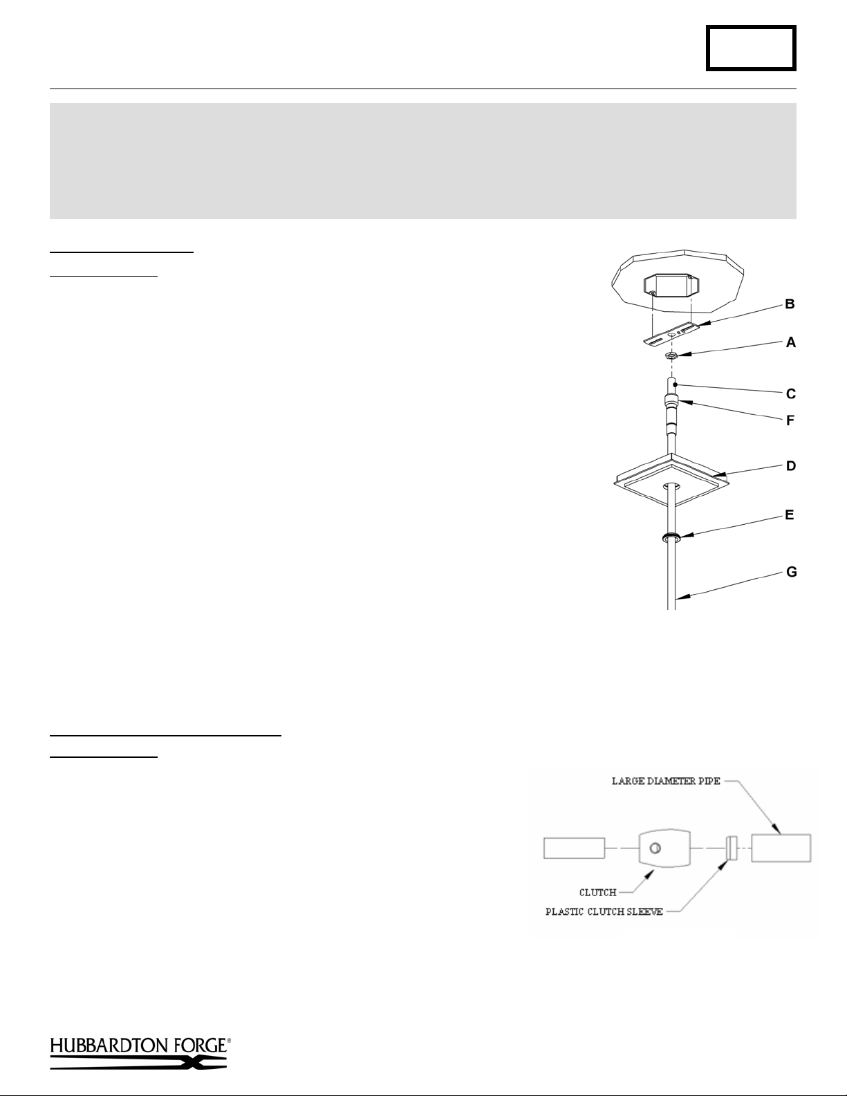
Prepare the Canopy (Figure 1)
Component Parts
A Jam Nut
B Crossbar
C Threaded Nipple
D Canopy
E Canopy Ring
F Coupling
G Canopy Pipe
Caution: Be sure power is off at the main breaker box prior to installation.
1. Carefully unpack the fixture from the carton.
2. Thread jam nut (A) and crossbar (B) onto threaded nipple (C) leave parts loose.
3. Using two machine screws (not provided), temporarily fasten the crossbar (B)
to the electric box.
Note: A new electric box comes with screws. When replacing a fixture, retain
the existing screws for use with the new fixture.
4. Adjust the length of threaded nipple (C) in crossbar (B) so that canopy ring (E)
will hold canopy (D) against the ceiling with no threads showing for best
appearance. When the correct adjustment is established, tighten jam nut (A)
against crossbar (B) to hold the adjustment.
5. Remove the crossbar and stem from the electrical box and proceed with the
assembly instructions.
(Figure 1)
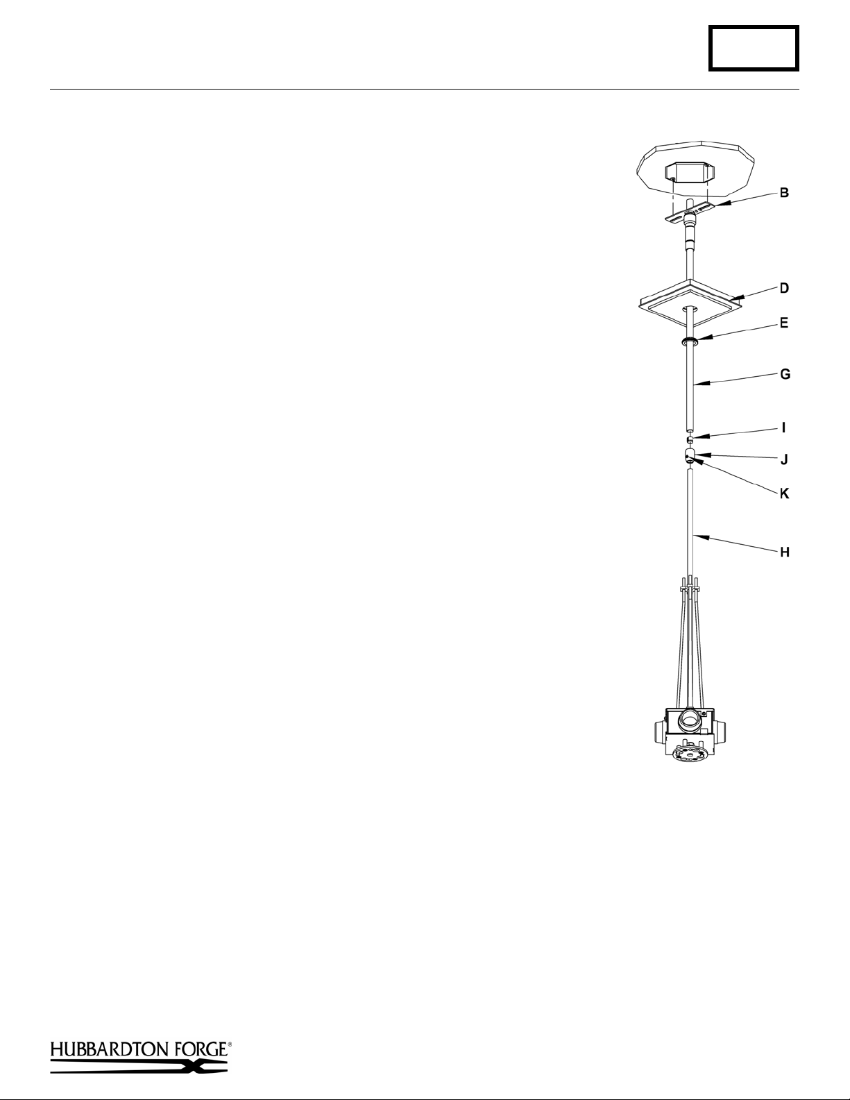
To Complete Assembly & Install
Component Parts
A Jam Nut
B Crossbar
C Threaded Nipple
D Canopy
E Canopy Ring
(Figures 2 & 3)
G Canopy Pipe
H Fixture Pipe
I Plastic Clutch Sleeve
J Clutch
K Set Screw
1. Thread wires from the fixture pipe (H) through the canopy
pipe (G).
2. Unscrew the clutch (J) from the canopy pipe (G); slide it across the
wires and onto the fixture pipe (H). Follow this with the plastic
clutch sleeve (I), oriented so the tapered end of the clutch sleeve
nests in the clutch (Figure 2).
Hand-Forged, Vermont-Made Lighting and Accessories
154 Route 30 South, Castleton, Vermont 05735
24618 Rev A
(Figure 2)
(continued)
Page 2
Assembly & Installation Instructions A248
Kirigami Four-Light Pendant 13-3305 Page 2 of 4
3. Slide the canopy pipe (G) as far as necessary to give you the total length of
the fixture which you desire. Be careful not to scratch the pipe surfaces and
to pull excess wire up through the canopy pipe (G). There must be a
minimum 1-1/2" of inner pipe inside the outer pipe. Screw clutch (J) onto
canopy pipe and hand-tighten the clutch to temporarily hold this adjustment.
The clutch is not securely fastened at this point; do not depend on it to hold
the fixture.
Important: To ensure full connection strength, be sure the tapered end of
the plastic clutch sleeve is oriented toward the clutch when assembled and
securely tighten set screw (Figure 2).
4. Using two machine screws (not provided), fasten the crossbar (B) to the
electric box.
Note: A new electric box comes with screws. When replacing a fixture, retain
the existing screws for use with the new fixture.
5. Using suitable wire connectors (not provided), connect fixture wires to
supply wires (white to white or ribbed side of the fixture cord, black to black
or smooth side). Run a pigtail lead from crossbar ground screw to the
junction box and connect all ground wires (bare copper or green to bare
copper or green). Push wires back into outlet box.
Caution: Make sure wire connectors are twisted on securely, and no bare
wire is exposed.
6. Slide fixture canopy (D) against ceiling, and secure with canopy ring (E).
7. Once the fixture is fastened to the ceiling, tighten the set screw (K) in clutch
(J) firmly with hex wrench provided. Only after the set screw (K) is tight
should you install the lower assembly.
8. Refer to following instructions to install bulb and shade assembly.
(Figure 3)
(continued)
Hand-Forged, Vermont-Made Lighting and Accessories
154 Route 30 South, Castleton, Vermont 05735
24618 Rev A
Page 3

Assembly & Installation Instructions A248
Kirigami Four-Light Pendant 13-3305 Page 3 of 4
To Assemble Bottom
Component Parts
L Hex Nut
M Diffuser Top Plate
N Nipple
O Bottom Assembly
P Shade
Q Threaded Knob (4)
R Threaded Stud (4)
S Diffuser
T Alignment Pin
U Spring
V Flat Head Screw (4)
1. Remove hex nut (L) (Figure 4). Save for later use.
2. Slip diffuser top plate (M) with flat head screws (V)
installed off bottom assembly (O) (Figure 4). Save
for later use.
3. Install shade (P) into bottom assembly by
slipping the holes in the shade over the
threaded studs (R) (Figure 5).
careful when installing shades not to allow the
shade to come in contact with the four
threaded studs. Contact with the studs will
damage the shade and cause visible
scratches.
4. Install knobs (Q) to keep shade (P) in place
(Figure 5).
(Figures 4, 5 & 6)
(Figure 4)
Note: Be
See Figure 6 (next page) for the remaining steps
unless another figure is referenced.
5. Slip diffuser (S) onto nipple (N) aligning the
alignment hole in the diffuser with the
alignment pin (T).
6. Thread the three flat head screws (V) installed
in the diffuser plate (M) so they protrude
slightly out the bottom of the plate.
7. Align the diffuser top plate (M) so the three
flat head screws (V) align with the three holes
in the diffuser (S) and slip onto the nipple (N)
until it rests on top of the diffuser.
8. Thread hex nut (L) onto nipple (N) until it sits
on top of the diffuser top plate (M). Tighten
the hex nut being careful not to over tighten.
9. Thread the three flat head screws (V) until
they are snug.
(Figure 5)
10. Slip the spring (U) onto the nipple.
11. Refer to instructions following to complete installation.
Hand-Forged, Vermont-Made Lighting and Accessories
154 Route 30 South, Castleton, Vermont 05735
24618 Rev A
(continued)
Page 4

Assembly & Installation Instructions A248
Kirigami Four-Light Pendant 13-3305 Page 4 of 4
To Install Bottom Assembly
(Figure 7)
(Figure 6)
Component Parts
O Bottom Assembly
V Flat Head Screws (4)
W Locking plate
1. Raise bottom assembly (O)
aligning flat head screws
with the larger holes in the
slots in the locking
plate (W).
2. Pushing up on the bottom
assembly (O) turn clockwise
until the bottom assembly
stops in the locked position.
3. Install light bulbs. Not
Included
(Figure 7)
4. Restore electricity at main breaker.
If you need further assistance, or find that you are missing any parts, please contact the dealer from which you purchased
this product. We hope you enjoy your fixture!
* Hubbardton Forge will not be liable for injury or damage caused by improper installation, lamping or use of this fixture.
Hand-Forged, Vermont-Made Lighting and Accessories
154 Route 30 South, Castleton, Vermont 05735
24618 Rev A
 Loading...