

Page 1
Assembly & Installation Instructions A168
For Vortis Pendant 13-3255F Page 1 of 3
CAUTION: FAILURE TO INSTALL THIS FIXTURE PROPERLY MAY RESULT IN SERIOUS PERSONAL
INJURY OR DEATH AND PROPERTY DAMAGE. We recommend installation by a licensed electrician.
This product must be installed in accordance with applicable installation code(s), by a person familiar with the
construction and operation of the product and the hazards involved.*
Caution: Do not exceed maximum wattage noted on fixture. Use only recommended bulbs with fixture.
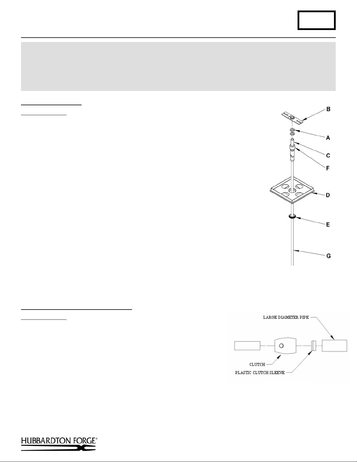
Prepare the Canopy (Figure 1)
Component Parts
A Jam Nut (2)
B Crossbar
C Threaded Nipple
D Canopy
E Canopy Ring
F Coupling
G Canopy Pipe
Caution: Be sure power is off at the main breaker box prior to installation.
1. Carefully unpack the fixture from the carton.
2. Thread Jam Nuts (A) and Crossbar (B) onto threaded nipple (C) leave parts
loose.
3. Using two machine screws (not provided), temporarily fasten the crossbar (B) to
the electric box.
Note: A new electric box comes with screws. When replacing a fixture, retain
the existing screws for use with the new fixture.
4. Adjust the length of Threaded Nipple (C) in crossbar (B) so that Canopy Ring
(E) will hold Canopy (D) against the ceiling with no threads showing for best
appearance. When the correct adjustment is established, tighten Jam Nuts (A)
against crossbar (B) to hold the adjustment.
5. Remove the crossbar and stem from the electrical box and proceed with the
assembly instructions.
(Figure 1)
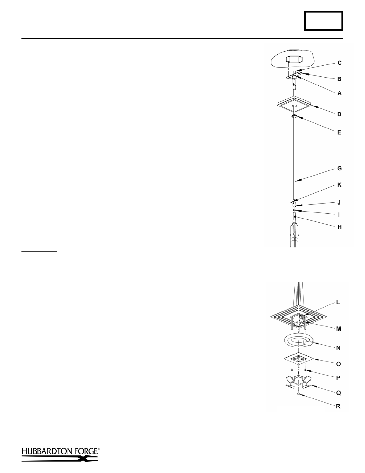
Complete Assembly & Install Fixture
Component Parts
A Jam Nut (2)
B Crossbar
C Threaded Nipple
D Canopy
E Canopy Ring
Caution: Be sure power is off at the main breaker box prior to
installation.
1. Thread crossbar (B) onto threaded nipple (C) until tight against jam
(Figures 2 & 3)
G Canopy Pipe
H Fixture Pipe
I Plastic Clutch Sleeve
J Clutch
K Set Screw
(Figure 2)
nuts (A).
2. Unscrew the clutch (J) from the fixture pipe (H); slide it across the wires and onto the canopy pipe (G). Follow this
with the plastic clutch sleeve (I), oriented so the tapered end of the clutch sleeve nests in the clutch (Figure 2).
(continued)
Hand-Forged, Vermont-Made Lighting and Accessories
P.O. Box 827, 154 Route 30 South, Castleton, Vermont 05735
21337 Rev A
Page 2
Assembly & Installation Instructions A168
(Fig
3
)
For Vortis Pendant 13-3255F Page 2 of 3
3. Thread wires from the fixture pipe (H) through the canopy pipe (G).
4. Slide the canopy pipe (G) as far as necessary to give you the total length of the
fixture which you desire. Be careful not to scratch the pipe surfaces and to pull
excess wire up through the canopy pipe (G). There must be a minimum 1-1/2" of
inner pipe inside the outer pipe. Screw clutch (J) onto canopy pipe and handtighten the clutch to temporarily hold this adjustment. The clutch is not securely
fastened at this point; do not depend on it to hold the fixture.
Important: To ensure full connection strength, be sure the tapered end of the
plastic clutch sleeve is oriented toward the clutch when assembled and securely
tighten set screw (Figure 2).
5. Using two machine screws (not provided), fasten the crossbar to the electric
box.
Note: A new electric box comes with screws. When replacing a fixture, retain
the existing screws for use with the new fixture.
6. Using suitable wire connectors (not provided), connect fixture wires to supply
wires (white to white or ribbed side of the fixture cord, black to black or smooth
side, and bare copper to bare copper or green supply). Push wires back into
outlet box.
Caution: Make sure wire connectors are twisted on securely, and no bare wire
is exposed.
7. Slide fixture canopy (D) against ceiling, and secure with canopy ring (E).
8. Refer instructions following to install bulb and glass.
Install Bulb
Component Parts
L Bulb Retainer
M Ballast
N Bulb
O Retainer Plate
P Screw (4)
Q Glass Retainer
R Tensioning Screw
(Figure 4)
1. Remove glass retainer (Q) from bottom of fixture by removing tensioning
screw (R) and turning the glass retainer 45 degrees to allow it to drop out of the
bottom of the fixture. Set retainer aside.
2. Remove the retainer plate (O) by loosening and removing the four screws (P).
3. Plug connection from ballast (M) to four pin location on bulb (N).
4. Snap bulb (N) in to bulb retainer (L).
5. Replace the retainer plate (O) and the four screws (P) and tighten.
ure
Hand-Forged, Vermont-Made Lighting and Accessories
P.O. Box 827, 154 Route 30 South, Castleton, Vermont 05735
(Figure 4)
(continued)
21337 Rev A
Page 3

Assembly & Installation Instructions A168
For Vortis Pendant 13-3255F Page 3 of 3
Install Glass
Component Parts
Q Glass Retainer
R Tensioning Screw
S Fixture Assembly
T Fixture slot
U Glass
V Retainer Tab
(Figure 5)
1. Place glass (U) into glass retainer (Q).
2. Lift glass (U) and glass retainer (Q) up to fixture assembly (S)
aligning retainer tabs (V) with fixture slots (T).
3. Lift so retainer tab (V) slips completely through fixture slot (T).
4. Turn glass (U) and glass retainer (Q) approximately 45 degrees
so glass retainer stays in place.
5. Turn tensioning screw (R) to secure glass retainer (Q) to fixture
assembly (S). Turn until snug and glass retainer will not spin
freely.
The ballast in this fixture is replaceable without cutting wires.
(Figure 5)
To Replace Ballast
Caution: Be sure power is off at the main breaker box
prior to replacing ballast.
(Figure 6)
1. Remove ballast from fixture by inserting a flat bladed
screwdriver behind tabs, located on the side of the
ballast adjacent to the mounting screws, and prying
outward.
2. Attach new ballast to fixture by aligning tabs
snapping it into place For replacement ballast
information, refer to the phone number printed on the
ballast case.
(Figure 6)
If you need further assistance, or find that you are missing any parts, please contact the dealer from which you purchased
this product. We hope you enjoy your fixture!
* Hubbardton Forge will not be liable for injury or damage caused by improper installation, lamping or use of this fixture.
Hand-Forged, Vermont-Made Lighting and Accessories
P.O. Box 827, 154 Route 30 South, Castleton, Vermont 05735
21337 Rev A
 Loading...