

Page 1
Assembly & Installation Instructions A194
For Four-Light Pendant 13-2205 Page 1 of 4
CAUTION: FAILURE TO INSTALL THIS FIXTURE PROPERLY MAY RESULT IN SERIOUS PERSONAL
INJURY OR DEATH AND PROPERTY DAMAGE. We recommend installation by a licensed electrician.
This product must be installed in accordance with applicable installation code(s), by a person familiar with the
construction and operation of the product and the hazards involved.*
Caution: Do not exceed maximum wattage noted on fixture. Use only recommended bulbs with fixture.
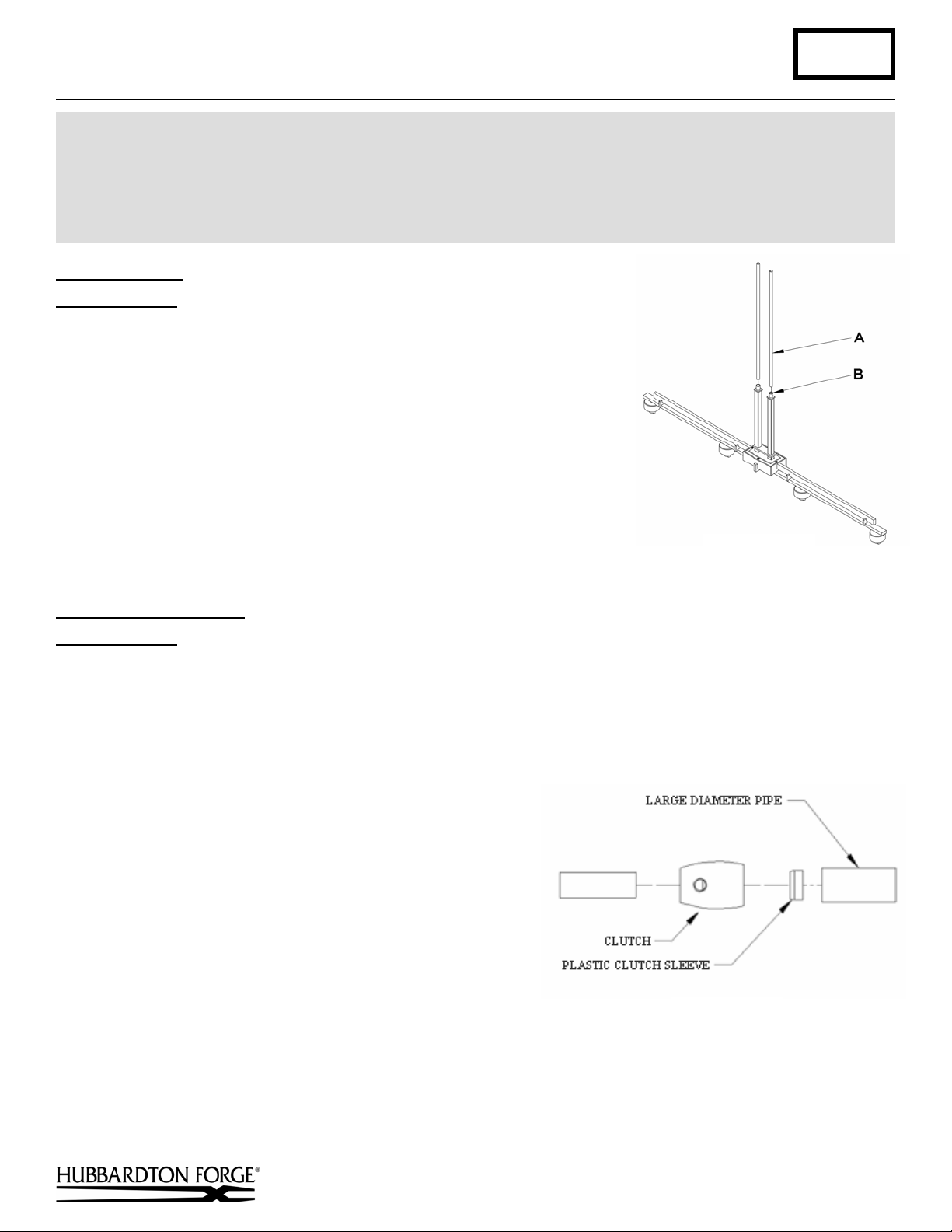
Stem Assembly (Figure 1)
Component Parts
A Fixture Pipe (2)
B Fixture Coupling (2)
1. Carefully unpack the fixture from the carton.
2. Carefully thread fixture pipe (A), threaded end first, over fixture wires.
3. Apply a drop of the supplied thread locking compound to the internal
threads at the top of the fixture coupling (B) and screw stem into fixture,
being careful not to twist the wires.
Note: Application of the thread locking compound is necessary to prevent
the stem from loosening during regular maintenance and cleaning of the
fixture. Be certain to apply the compound.
4. See instructions below to complete the installation.
(Figure 1)
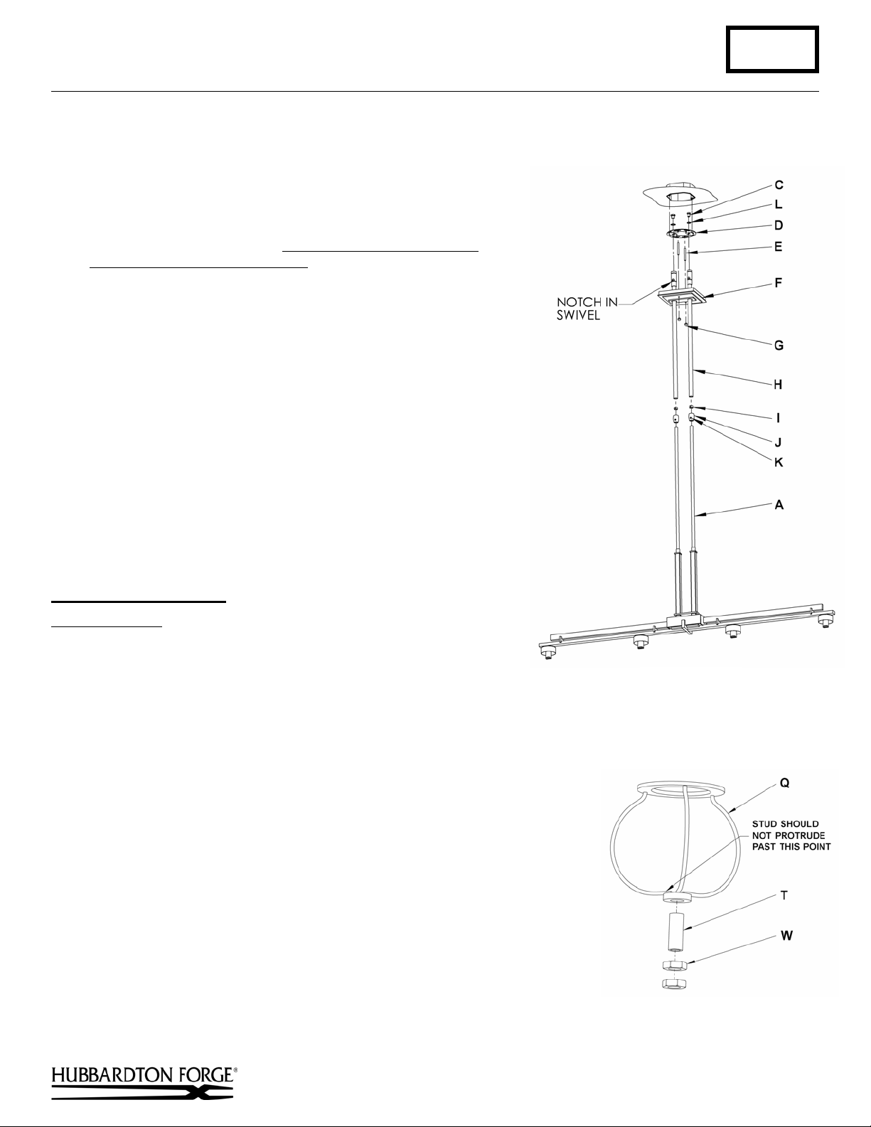
To Complete Assembly
Component Parts
A Fixture Pipe (2)
C Hex Head Nipple (2)
D Crossbar
E Threaded Stud (2)
Caution: Be sure power is off at the main breaker box prior to installation.
(Figures 2 & 3)
F Canopy
G Knurled Ball (2)
H Canopy Pipe (2)
I Plastic Clutch Sleeve (2)
1. Thread the wires from the fixture pipe (A) into and
through the canopy pipe (H) up through the canopy (F).
2. Unscrew the clutch (J) from the canopy pipe (H); slide it
across the wires and onto the fixture pipe (A). Follow this
with the plastic clutch sleeve (I), oriented so the tapered
end of the clutch sleeve nests in the clutch.
3. Slide the canopy pipe (H) as far as necessary to give you
the total length of the fixture which you desire. Be careful
not to scratch the pipe surfaces and to pull excess wire up
through the canopy pipe (H). Screw clutch (J) onto canopy
pipe (H). There must be a minimum 1-1/2" of inner pipe
inside the outer pipe. Hand-tighten the clutch to
temporarily hold this adjustment. The clutch is not securely
fastened at this point; do not depend on it to hold the fixture.
Important: To ensure full connection strength, be sure the
tapered end of the plastic clutch sleeve is oriented toward the
clutch when assembled and securely tighten set screw (Figure 2).
J Clutch (2)
K Set Screw (2)
L Lock Washer (2)
(Figure 2)
(continued)
Hand-Forged, Vermont-Made Lighting and Accessories
P.O. Box 827, 154 Route 30 South, Castleton, Vermont 05735
22423 Rev A
Page 2
Assembly & Installation Instructions A194
For Four-Light Pendant 13-2205 Page 2 of 4
4. Slide canopy (F) over canopy pipe (H) being careful not to scratch finish.
Slide down until the canopy rests against clutch (J).
5. Thread studs (E) through appropriate holes in crossbar (D) to match
holes in canopy (F).
6. Attach crossbar (D) to both canopy pipes (H) using hex nut nipple
(C) and lock washer (L).
aligned in the same direction. For sloped ceilings the notches
should face towards the down side.
7. Using two machine screws (not provided), fasten the crossbar (D) to
the electric box.
When replacing a fixture, retain the existing screws for use with the
new fixture.
Note: A new electric box comes with screws.
8. Using suitable wire connectors (not provided) connect fixture wires
to supply (white to white and black to black). Connect all ground
wires to green ground screw.
are twisted on securely, and no bare wire is exposed.
9. Slide canopy (F) over threaded studs (E) and push firmly to ceiling,
making sure that no wires are pinched between fixture canopy and
ceiling. Fasten with knurled balls (G). Be sure studs are fully
seated in the knurled balls.
10. Refer instructions below and install glass/shade for option
that was purchased.
11. Restore electricity at main breaker.
To Install Shade Option
Note: Be sure both swivel notches are
Caution: Make sure wire connectors
(Figures 4 & 5)
Component Parts
M Socket (4)
N Bulb (Included)(4)
O Top Diffuser (4)
P Shade (4)
Q Harp (4)
R Washer (4)
S Retainer (4)
T Threaded Stud (4)
U Inner Glass (4)
V Threaded Cap (4)
W Hex Nut (8)
1. Install threaded stud (T) into harp (Q) followed by two hex nuts (W)
(Figure 4).
2. Install light bulb (N). Be careful not to touch bulb with bare hands; oil
from the hands will dramatically reduce bulb life.
3. Slip top diffuser (O), shade (P), harp (Q) and washer (R) over socket (M).
4. Thread retainer (S) onto socket (M) until snug to washer (R).
(Figure 3)
(Figure 4)
(continued)
Hand-Forged, Vermont-Made Lighting and Accessories
P.O. Box 827, 154 Route 30 South, Castleton, Vermont 05735
22423 Rev A
Page 3

Assembly & Installation Instructions A194
For Four-Light Pendant 13-2205 Page 3 of 4
5. Slip inner glass (U) onto threaded stud (T) until it rests against the bottom
hex nut (W).
6. Install threaded cap (V) until snug against inner glass (U). Be careful
not to over tighten.
7. Restore electricity at main breaker.
(Figure 5)
To Assemble Cylinder Glass for Double Glass Option
Component Parts
X Cylinder Glass
Y 8-32 Button Head Screw (3)
Z Rubber Washer (3)
AA Diffuser
BB Glass Gripper (3)
CC 8-32 Set Screw (3)
(Figure 6)
1. Install rubber washer (Z) to surface of glass gripper (BB).
2. Slide all three glass grippers (BB) on to diffuser (AA) in approximate
locations to line up with holes in cylinder glass. Gripper should be
placed on diffuser so the set screw is towards the bottom of the glass
cylinder.
3. Tighten set screw (CC) slightly to keep grippers from falling off but
allowing slight movement for alignment.
4. Lower diffuser (AA) inside cylinder glass (X) lining up the first
gripper with the first hole in the cylinder glass (X) and install button
head screw (Y).
5. Install the other two glass grippers (BB) each with a button head
screw (Y).
6. Tighten all three button head screws (Y). Do not over tighten.
7. Align diffuser (AA) to be centered inside cylinder glass (X) and
tighten all three set screws (CC). Do not over tighten.
Hand-Forged, Vermont-Made Lighting and Accessories
P.O. Box 827, 154 Route 30 South, Castleton, Vermont 05735
(Figure 6)
(continued)
22423 Rev A
Page 4

Assembly & Installation Instructions A194
For Four-Light Pendant 13-2205 Page 4 of 4
To Install Double Glass Option
Component Parts
M Socket (4)
N Bulb (Included)(4)
Q Harp (4)
R Washer (4)
S Retainer (4)
1. Install threaded stud (T) into harp (Q) (Figure 7).
2. Install light bulb (N). Be careful not to touch bulb with bare hands; oil
from the hands will dramatically reduce bulb life.
3. Slip outer glass assembly (DD), harp (Q) and washer (R) over
socket (M).
4. Thread retainer (S) onto socket (M) until snug to washer (R).
5. Install rubber stop (EE) to top edge of inner glass (U) equally spaced
around the diameter.
6. Slip inner glass (U) onto threaded stud (T) until it rests against the bottom
of harp (Q).
7. Install threaded cap (V) until snug against the bottom of inner glass (U).
Be careful not to over tighten.
8. Restore electricity at main breaker.
If you need further assistance, or find that you are missing any parts, please contact the dealer from which you purchased
this product. We hope you enjoy your fixture!
* Hubbardton Forge will not be liable for injury or damage caused by improper installation, lamping or use of this fixture.
(Figures 7 & 8)
T Threaded Stud (4)
U Inner Glass
V Threaded Cap (4)
DD Outer Glass Assembly (Assembled above)(4)
EE Rubber Stop (12)
(Figure 7)
(Figure 8)
Hand-Forged, Vermont-Made Lighting and Accessories
P.O. Box 827, 154 Route 30 South, Castleton, Vermont 05735
22423 Rev A
 Loading...