

Page 1
Assembly & Installation Instructions A158
For Impressions Semi-Flush 12-6751 & 12-6751F Page 1 of 2
CAUTION: FAILURE TO INSTALL THIS FIXTURE PROPERLY MAY RESULT IN SERIOUS PERSONAL
INJURY OR DEATH AND PROPERTY DAMAGE. We recommend installation by a licensed electrician.
This product must be installed in accordance with applicable installation code(s), by a person familiar with the
construction and operation of the product and the hazards involved.*
Caution: Do not exceed maximum wattage noted on fixture. Use only recommended bulbs with fixture.
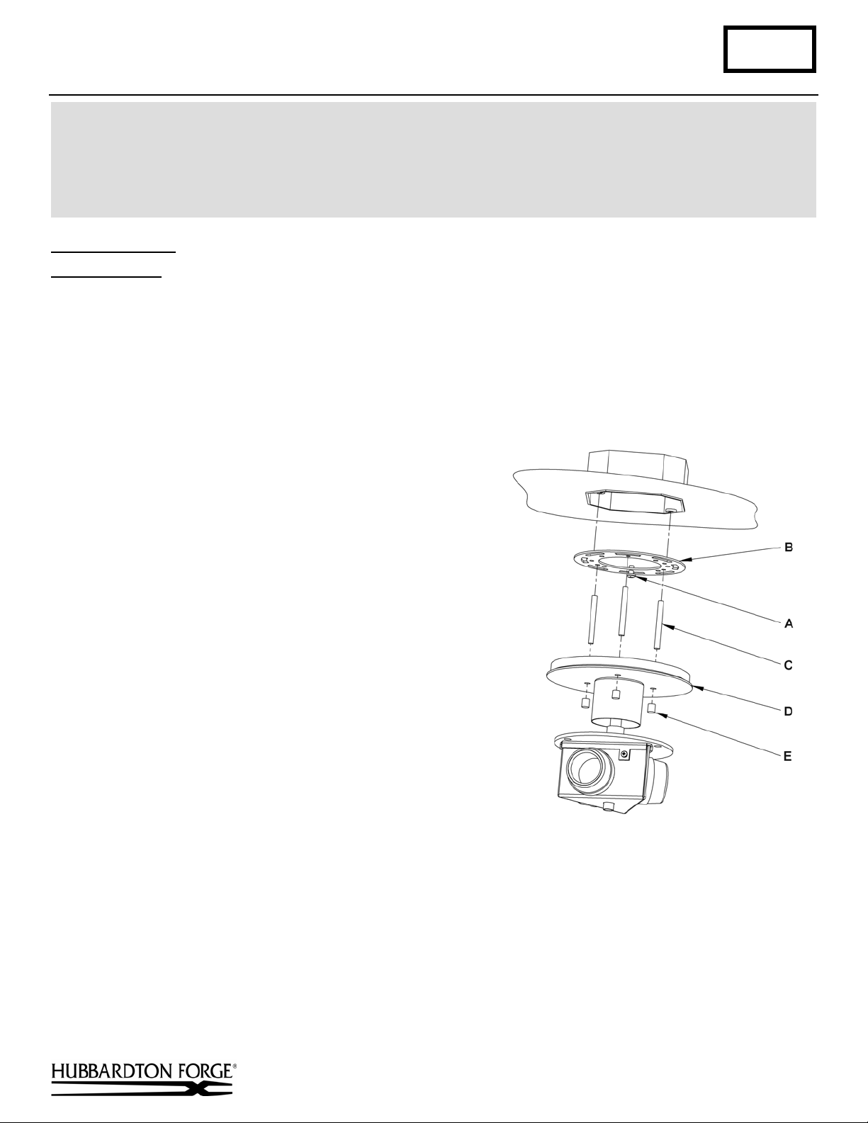
To Install Fixture (Figure 1)
Component Parts
A Ground Screw
B Cross Bar
C Threaded Stud (3)
D Canopy
E Barrel Knobs (3)
Caution: Be sure power is off at the main breaker box prior to installation
1. Carefully unpack the fixture from the carton.
2. Thread studs (C) through appropriate holes in cross
bar (B) to match hole centers in canopy (D). Move
ground screw (A) to another available threaded hole if
necessary.
3. Using two machine screws (not provided) fasten cross
bar (B) to the electric box using outer oval holes to
orient fixture to desired hanging position.
Note: A new electric box comes with screws. When
replacing an existing fixture, retain the screws for use
with the new fixture.
5. Using suitable wire connectors (not provided); connect
fixture wires to supply wires (white to white and black
to black). Connect all ground wires to green ground
screw (A).
Caution: Make sure wire connectors are twisted on
securely, and no bare wire is exposed.
6. Slide fixture canopy (D) over threaded studs and push
firmly to ceiling, making sure that no wires are
pinched between fixture canopy and ceiling. Fasten
with barrel knobs (E). Be sure studs (C) are fully
seated in barrel knobs (E).
(Figure 1)
Hand-Forged, Vermont-Made Lighting and Accessories
P.O. Box 827, 154 Route 30 South, Castleton, Vermont 05735
(continued)
21236
Page 2

Assembly & Installation Instructions A158
For Impressions Semi-Flush 12-6751 & 12-6751F Page 2 of 2
To Install Glass
Component Parts
F Glass
G Spider Assembly
H Socket Assembly
I Screws (3)
J Diffuser
K Washer
(Figures 2 & 3)
1. Place glass (F) into notches of spider assembly (G)
(Figure 2).
2. Lift spider assembly (G) with glass (F) installed over socket
assembly (H) and place on top of socket assembly.
3. Rotate spider assembly (G) until all three holes match up
with the three holes in washer (K).
4. Thread screws (I) from bottom of washer (K) into spider
assembly (G).
5. Install light bulbs. Fluorescent version bulbs are included.
6. Insert the diffuser (J) up into the fixture at an angle then
level it and gently lower onto the lowest tabs of the spider
assembly (G).
(Figure 2)
7. Restore electricity at main breaker.
(Figure 3)
If you need further assistance, or find that you are missing any parts, please contact the dealer from which you purchased
this product. We hope you enjoy your fixture!
* Hubbardton Forge will not be liable for injury or damage caused by improper installation, lamping or use of this fixture.
Hand-Forged, Vermont-Made Lighting and Accessories
P.O. Box 827, 154 Route 30 South, Castleton, Vermont 05735
21236
 Loading...