

Page 1
Assembly & Installation Instructions A258
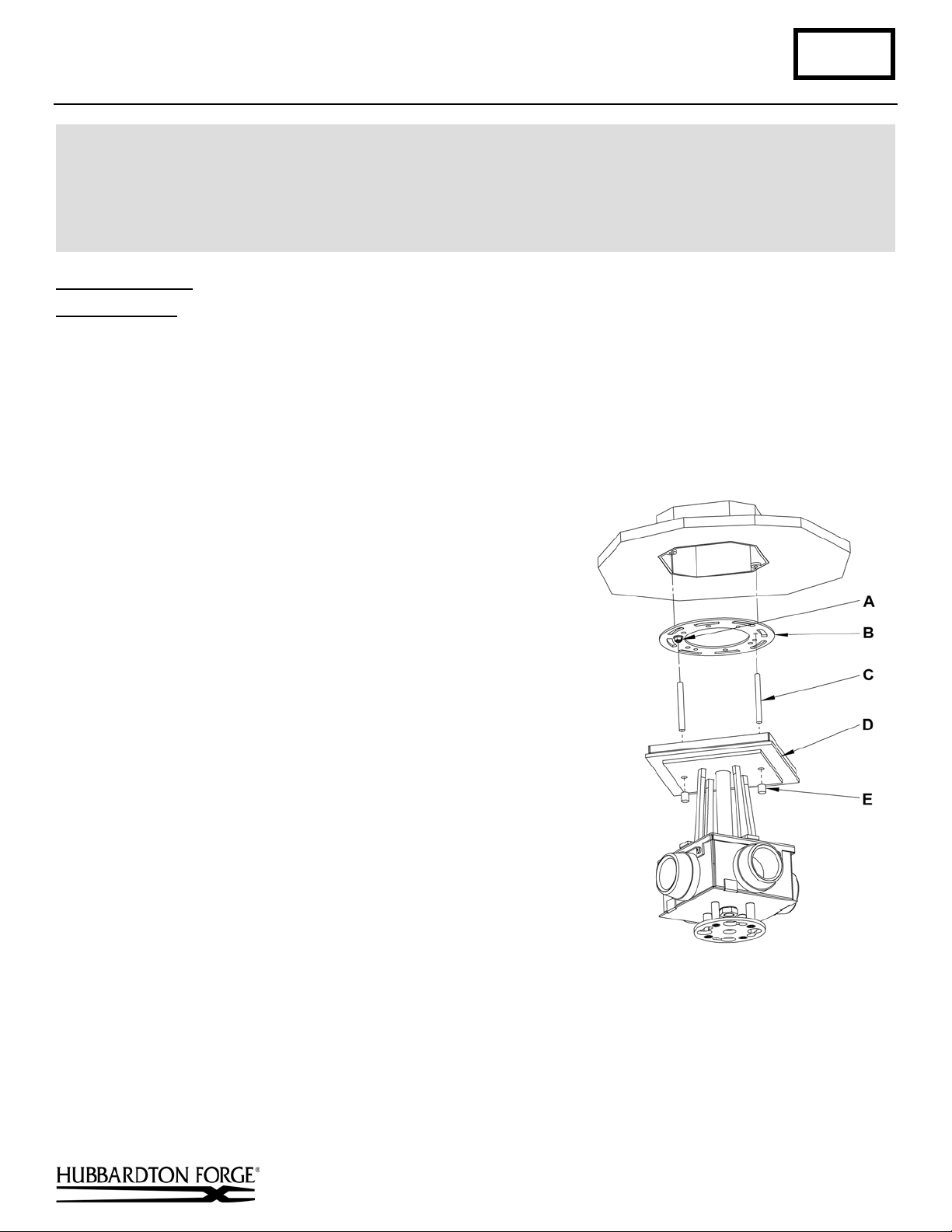
(Figure 1)
CAUTION: FAILURE TO INSTALL THI S FIXTURE PROPERLY MAY RESULT I N SERIO US PERSO NAL
Semi-Flush Kirigami Four Light 12-3305 & 12-3307 Page 1 of 3
INJURY OR DEATH AND PROPERTY DAMAGE. We rec o mm e nd installation by a licensed electrician.
This product must be installed in accordance with applicable installation code(s), by a person familiar with the
construction and operation of the product and the hazards involved.*
Caution: Do not exceed maximum wattage noted on fixture. Use only recommended bulbs with fixture.
To Install Fixture (Figure 1)
Component Parts
A Ground Screw
B Cross Bar
C Threaded Stud (2)
D Canopy
E Barrel Knobs (2)
Caution: Be sure power is off at the main breaker box prior to installation.
1. Carefully unpack the fixture from the carton.
2. Thread studs (C) through appropriate holes in cross bar (B) to
match hole centers in canopy (D). Move ground screw (A) to
another available threaded hole if necessary.
3. Using two machine screws (not provided) fasten cross bar (B) to
the electric box using outer oval holes to orient fixture to desired
hanging position.
Note: A new electric box comes with screws. When replacing an
existing fixture, retain the screws for use with the new fixture.
4. Using suitable wire connectors (not provided); connect fixture
wires to supply wires (white to white and black to black). Run a
pigtail lead from crossbar ground screw (A) to the junction box
and connect all ground wires (bare copper or green to bare copper
or green).
securely, and no bare wire is exposed.
Caution: Make sure wire connectors are twisted on
5. Slide fixture canopy (D) over threaded studs and push firmly to
ceiling, making sure that no wires are pinched between fixture
canopy and ceiling. Fasten with barrel knobs (E). Be sure studs
(C) are fully seated in barrel knobs (E).
Hand-Forged, Vermont-Made Lighting and Accessories
154 Route 30 South, Castleton, Vermont 05735
24793 Rev D
(continued)
Page 2

Assembly & Installation Instructions A258
(Figure 3)
(Figure 2)
Semi-Flush Kirigami Four Light 12-3305 & 12-3307 Page 2 of 3
To Assemble Bottom (Figures 2, 3 & 4)
Component Parts
F Hex Nut
G Diffuser Top Plate
H Nipple
I Bottom Assembly
J Shade
K Threaded Knob (4)
L Threaded Stud (4)
M Diffuser
N Alignment Pin
O Spring
P Flat Head Screw (4)
1. Remove hex nut (F) and the four threaded knobs (K) (Figure 4).
Save for later use.
2. Slip diffuser top pla te (G ) with flat head screws (P) installed off
bottom assembly (I) (Figure 4). Save for later use.
3. Install shade (J) into bottom assembly by
slipping the holes in the shade over the threaded
studs (L) (Figure 5).
installing shades not to allow the shade to come
in contact with the four threaded studs. Contact
with the studs will damage the shade and cause
visible scratches.
4. Install knobs (K) to keep shade (J) in place
(Figure 5).
See Figure 4 (next page) for the remaining steps
unless another figure is referenced.
5. Slip diffuser (M) onto nipple (H) aligning the
alignment hole in the diffuser with the alignment
pin (N).
6. Thread the four flat head screws (P) installed in
the diffuser plate (G) so they protrude slightly
out the bottom of the plate.
7. Align the diffuser top plate (G) so the three flat
head screws (P) align with the three holes in the
diffuser (M) and slip onto the nipple (H) unt il it
rests on top of the diffuser.
8. Thread hex nut (F) onto nipple (H) until it sits
on top of the diffuser top plate (G). Tighten the
hex nut being careful not to over tighten.
9. Thread the three flat head screws (P) until they are snug.
10. Slip the spring (O) onto the nipple.
11. Refer to instructions following to complete
installation.
Note: Be careful when
(continued)
Hand-Forged, Vermont-Made Lighting and Accessories
154 Route 30 South, Castleton, Vermont 05735
24793 Rev D
Page 3

Assembly & Installation Instructions A258
(Figure 4)
(Figure 5)
Semi-Flush Kirigami Four Light 12-3305 & 12-3307 Page 3 of 3
To Install Bottom Assembly (Figure 5)
Component Parts
I Bottom Assembly
P Flat Head Screws (4)
Q Locking plate
1. Install light bulbs. Not Included
2. Raise bottom assembly (I) aligning flat
head screws with the larger holes in the
slots in the locking plate (Q).
3. Pushing up on the bottom assembly (I)
turn clockwise until the bottom assembly
stops in the locked position.
4. Restore electricity at main breaker.
If you need further assistance, or find that you are missing any parts, please contact the dealer from which you purchased
this product. We hope you enjoy your fixture!
* Hubbardton Forge will not be liable for injury or damage caused by improper installation, lamping or use of this fixture.
Hand-Forged, Vermont-Made Lighting and Accessories
154 Route 30 South, Castleton, Vermont 05735
24793 Rev D
 Loading...