

Page 1
Huba Control AG - Type 712 - Edition 07/2015 - 116381
1
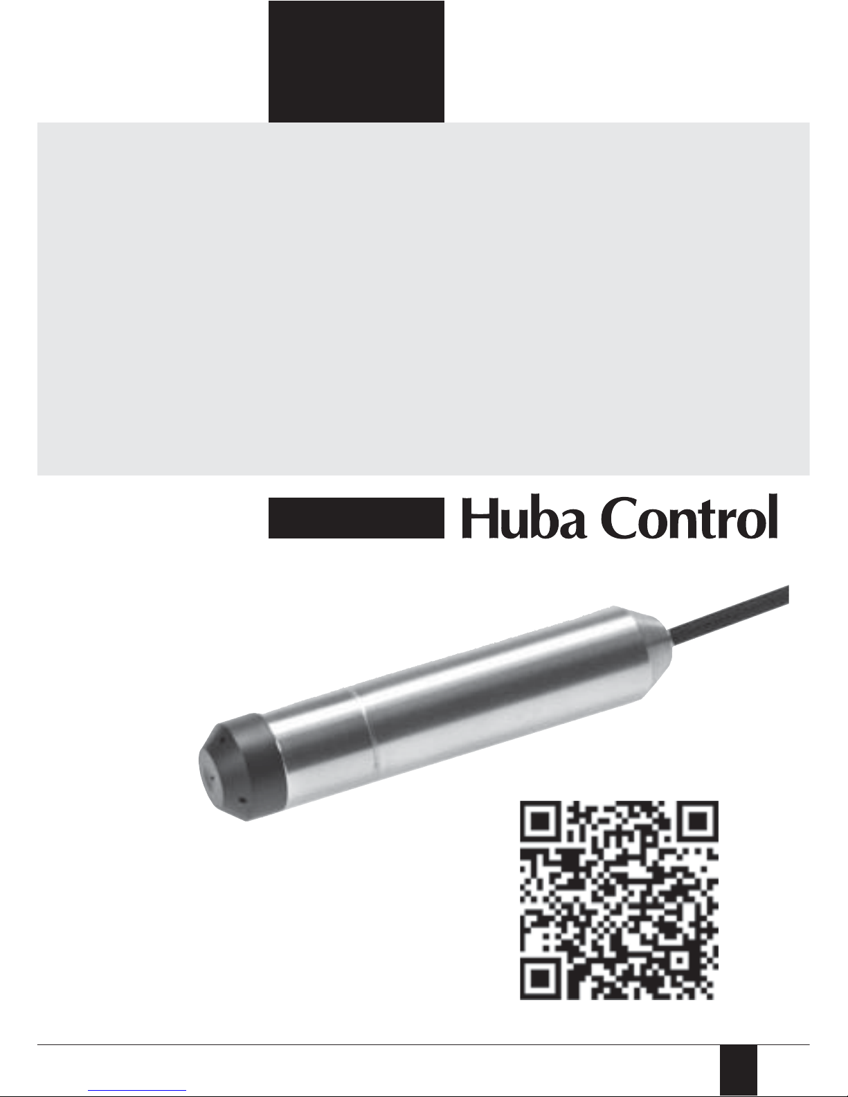
712
OEM Level sensing pressure transmitter
Operating instructions
Page 2
2
Huba Control AG - Type 712 - Edition 07/2015 - 116381
English
Safety Guidelines
These instructions contains notices intended to ensure personal safety, as well
as to protect the products and connected equipment against damage. These
notices are highlighted by the symbols shown below and graded according to
severity by the following texts.
This warning signifies an imminent danger.
Injuries or even death can arise from failing the warnings.
This warning signifies a potential danger.
Injuries or even death can arise from failing the warnings.
This warning signifies a potential dangerous situation,
which can lead to medium or light injuries.
Only trained qualified personnel shall execute this work.
DANGER
CAUTION
ATTENTION
Page 3

Huba Control AG - Type 712 - Edition 07/2015 - 116381
3
General Notes
NOTE
Dear customer,
for reasons of clarity the instructions does not contain detailed information
about all types of products and cannot take into account every conceivable
case of installation, operation or maintenance.
If you require further information or should problems occur which are not
sufficiently explained in the instructions, you can consult your local Siemens
branch to obtain the necessary information.
May we also draw your attention to the fact that the contents of the operating instructions are not part of a previous or existing agreement, approval or
legal relationship or an amendment thereof. All obligations of the Siemens
AG result from the contract of purchase which also contains the full and
solely valid warranty agreement. These contractual warranty conditions are
neither extended nor restricted by the contents of the operating instructions.
The contents reflect the technical state at the time of going to
print. Subject to technical modifications in the course of further
development.
Intrinsically safe devices lose their license as soon as they are operated on circuits which do not meet the requirements of the examination certificate valid
in your country. The device may be operated with high pressure and corrosive
media. Therefore serious injuries and/or considerable material damage cannot
be ruled out in the event of improper handling of the device.
The equipment may only be used for the purposes specified in this
operating instructions.
CAUTION
Page 4
4
Huba Control AG - Type 712 - Edition 07/2015 - 116381
Qualified Personnel
are persons familiar with the insallation, assembly, commisioning and operation of the product and who have the appropriate qualifications for their
activities such as:
training or instruction or authorization to operate and maintain devices/
systems according to the standard of safety technology for elecrical
circuits, high pressures and corrosive as well as hazardous media.
for devices with explosion protection: training or instruction or authori zation to be allowed to work on electrical circuits for potentially explosive
systems.
training or instruction according to the standards of safety engineering in
the care and use of suitable safety equipment.
Only trained qualified personnel shall execute this work.
Modules which are sensitive to electrostatic charge may be destroyed by
voltages which are far below the human level of perception. These voltages
occur already when you touch a component or electrical connections of a
module without first discharging yourself electrostatically. The damage incurred by a module as a result of an overvoltage is not usually immediately perceptible but only becomes noticeable after a long time in operation.
Therefore, a suitable equipotential bonding must be guaranteed when repairing the device.
(1)
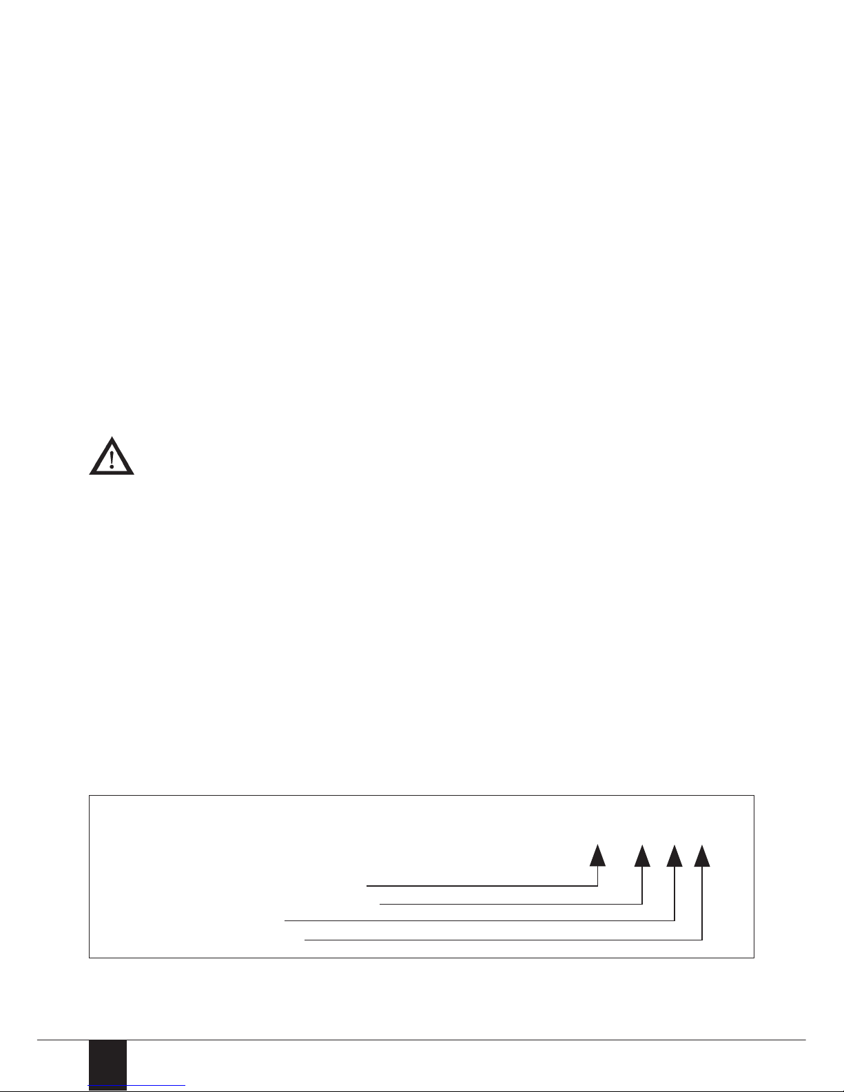
YYMMDD - example 100912
The date of manufacture can be seen on the label of the
pressure level transmitter, for example:
YYMMDD-XXX-XX-XXXX
Date as ıyear-month-day„
3 digits of the order number
Order position
Single part number
(1)
Page 5
Huba Control AG - Type 712 - Edition 07/2015 - 116381
5
Application in hazardous area
with current output 4 ... 20 mA)
The operation is acceptable into the intrinsically safe circuits only, with the
following maximum values:
Power supply Ui ª 30 V
Current Ii ª 100 mA
Power dissipation Piª 750 mW
Consider the following data:
The length of the cable, which conveys the input/output signal, must be taken
in consideration because of its internal inductivity and capacity:
Internal capacitance Ci = 0 nF + 0.08 nF/m
Internal inductance Li = 0 øH + 1.0 øH/m
Mark in accordance acc. RL 94/9/EG
II 1 G
Protection type mark Ex ia IIC T4 Ga
The maximum allowable operating temperature Ta is from -20 to +80C. For
the applications as Category-1- apparatus the maximum allowable operating
temperature should be maximum +60C. The transmitter can be used in
open tanks, channels etc.
For the applications as Category-1- apparatus group IIC is not allowed the
critical electrostatic charging over the protection cap surface.
The valid standards and rules should to be considered during the installation
of devices.
DANGER
Page 6

6
Huba Control AG - Type 712 - Edition 07/2015 - 116381
Application in hazardous area
with ratiom. output 10 ... 90%)
The operation is acceptable into the intrinsically safe circuits only, with the
following maximum values:
Power supply Ui ª 15 V
Current Ii ª 200 mA
Power dissipation Pi ª750 mW
Consider the following data:
The length of the cable, which conveys the input/output signal, must be taken
in consideration because of its internal inductivity and capacity:
Internal capacitance Ci = 0.5 nF + 0.08 nF/m
Internal inductance Li = 0 øH + 1.0 øH/m
Mark in accordance acc. RL 94/9/EG
II 1 G
Protection type mark Ex ia IIC T4 Ga
The maximum allowable operating temperature Ta is from -20 to +80C. For
the applications as Category-1- apparatus the maximum allowable operating
temperature should be maximum +60C. The transmitter can be used in
open tanks, channels etc.
For the applications as Category-1- apparatus group IIC is not allowed the
critical electrostatic charging over the protection cap surface.
The valid standards and rules should to be considered during the installation
of devices.
DANGER
Page 7

Huba Control AG - Type 712 - Edition 07/2015 - 116381
7
Construction
The level sensor consists of a ceramic measuring cell (relative and absolute
pressure) with an amplified electronic and is adjusted in the requested pressure range. The sensor, the electronic and the connection cable are hermetically
encapsulated in a stainless steel case. The measuring diaphragm is protected
from outside influences by a protection cover. A venting pipe is included in the
connection cable for the relative version. The sensor, the electronic and the connection cable are placed in a hermetic encapsulated small case.
The wide temperature range of the level sensor is compensated.
Application
The Type 712 transmitter is used for hydrostatic measurement of liquid levels,
e.g. in water supply, ship installations, in the oil and gas industry etc.
The calculation of the temperature related to the power supply with NTC
resistance is as follows:
T
TEMP
Temperature NTC [ÀC] R 20'000 [Ω]
T0 -273.15 [ÀC] a 0.001204001
T25 25 [ÀC] b 0.000208775
U
TEMP
Voltage at NTC [V] c 0.000000294
Consider the chemical resistance of sensor, case, O-ring and connection cable
with the media.
CAUTION
a + b • In
•
+ c • In
•
3
Page 8

8
Huba Control AG - Type 712 - Edition 07/2015 - 116381
Calculation of level
General level with relative pressure sensor:
General level with absolute pressure sensor:
which
and
Using a second level sensor as barometric air pressure sensor.
For level sensor with current output use nominal signal values for I
TS
... instead of variables UTS ... (resp. I
Baro
... instead of U
Baro
...).
Simplification of formula for level sensor with ratiometric output:
Using a second level sensor as barometric air pressure sensor
Legende:
h level [m] ρ density of media [kg/m3]
g acceleration of fall 9.80665 [m/s2]
∆p measured relative pressure [Pa]
PTS measured pressure of level sensor [Pa] UTS signal on level sensor output [V or mA]
P
BARO
measured pressure of barometer [Pa] U
BARO
Signal on barometer output [V or mA]
P
TS_NP
minimal nominal pressure of level sensor [Pa] U
TS_NP
minimal nominal signal of level sensor [V or mA]
P
TS_EW
maximum nominal pressure of level sensor [Pa] U
TS_EW
maximum nominal signal of level sensor [V or mA]
P
BARO_NP
minimal nominal pressure of barometer [Pa] U
BARO_NP
minimal nominal signal of barometer [V or mA]
P
BARO_EW
maximum nominal pressure of barometer [Pa] U
BARO_EW
maximum nominal signal of barometer [V or mA]
Page 9

Huba Control AG - Type 712 - Edition 07/2015 - 116381
9
Mode of operation
The pressure of the medium acts on the keramic sensor which is deflected to
transmit the pressure to the piezo-resistive bridge in the measuring sensor.
Every sensor is compensated for changes in temperature and operates within
a wide temperature range.
The output signal of the sensor is fed to an electronic circuit which converts
it into a standard voltage and current output. The hydrostatic pressure which
is proportional to the submersion depth acts on the diaphragm of the sensor.
This pressure is compared with the atmospheric pressure which acts on the
other side of the sensor by means of the vent pipe in the connecting cable
(at relative pressure).
Installation
The level pressure transmitter
712 is installed hanging downwards on the cable. In moving
media, the transmitter must
be fixed to prevent measuring
errors. This can be done with a
guide tube. Make sure that the
inlet openings on the protective
cap of the level pressure transmitter are not soiled in order to
guarantee perfect functioning.
Calibration
The transmitter has been calibrated to the measuring range at the factory and
cannot be re-calibrated.
Maintenance
The level transmitter requires no maintenance.
h
h - Fluid level
- Measurement reference height
A - Distance from protection cover to the position of measuring diaphragm
B - distance from beginning of thread to the position of measuring diaphragm
(versions without protection cover)
Page 10

10
Huba Control AG - Type 712 - Edition 07/2015 - 116381
Operating conditions
The following points should be noted particularly when using the device:
The maximum permissible pressure pmax of the transmitter may not be
exceeded.
The temperature of the medium in contact with the transmitter may
not exceed 80ÀC.
Avoid formation of ice on the process input of the transmitter because
this could damage the diaphragm.
Prevent soiling of the transmitter input.
Avoid obstruction to the vent pipes in the special cable (influences the
measuring accuracy).
CAUTION
Page 11

Huba Control AG - Type 712 - Edition 07/2015 - 116381
11
Technical overview
Temperature Medium -20 ... +80 ÀC
Storage -40 ... +80 ÀC
Overload / rupture pressure 3 x fs
Output Power supply Load
4 ... 20 mA 10 ... 30 VDC
Power supply - 10 V
[Ohm]
ratiom. 10 ... 90% 5 VDC μ10% > 10 kOhm / < 100 nF
ratiom. 10 ... 90% 5 VDC μ10% wiht temp. > 10 kOhm / < 100 nF
0 ... 10 V 12 ... 30 VDC > 10 kOhm / < 100 nF
Polarity reversal Short circuit proof and protected against polarity
protection reversal. Each connection is protected against
crossover up to max. supply voltage.
Protection standard IP 68
Materials
Sensor Ceramic Al
2O3
(96%)
Case Stainless steel 1.4404 / AISI 316L
Cable PE
Protection cover PPE
Sealing material FPM, EPDM
Test / Admissions
Electromagnetic compatibility CE-conform
acc. EN 61326-2-3
Drinking water approval WRAS / ACS
Ex-protection 1) Ex II 1G Ex ia IIC T4 Ga
Accessories Order number
Cable hanger 118026
Connection box 118027
Test adapter 118028
Protection cover (pack of 10) 118068
additional weight 118093
Humidity protection element (pack of 10) 118067
1)
Max. cable length is 500 m
0.02 A
Page 12

12
Huba Control AG - Type 712 - Edition 07/2015 - 116381
Electrical connections
Device design with
explosion protection: 4 ... 20 mA
The grounding connection is
conductively connected to the level
transmitter housing. The ground
conductor of level transmitter must
be connected to the equipotential
bonding system of the plant.
Device design with explosion
protection: ratiom. 10 ... 90%
The electronic GND is connected
with a 1MΩ resistor to the level
transmitter housing. The GND conductor of level transmitter must
be connected to the equipotential
bonding system of the plant.
4 ... 20 mA
brown
white
green
brown
white
green
ratiom. 10 ... 90% with temperature
brown
white
green
yellow
brown
white
green
brown
white
green
brown
white
green
yellow
Page 13

Huba Control AG - Type 712 - Edition 07/2015 - 116381
13
Dimensions Accessories
.DEHO
cable hangertest adapteradditional weight
(1) mounting hole
(2) vent valve
(A) measuring value process
(B) vent pipe
(C) to the transmitter
(A)
B)
(C)
Connection box
WARNUNG
In approved -area is be should avoided electrostatic
charge.
~200 g
1) Inside thread Iso 228/1-G ¼ A
hot-dip alvanized
steel PA6 glass
fibre reinforced
Cable
Page 14

14
Huba Control AG - Type 712 - Edition 07/2015 - 116381
Description Lable
Lable ATEX
Lable connection box
12
11
1
10
14
7
13
15
8
1
2
3
7
8
4
9
10
11
5
Page 15

Huba Control AG - Type 712 - Edition 07/2015 - 116381
15
1 - Article number
2 - Nominal pressure range
3 - Max. admissible over pressure
4 - Output signal range
5 - Electrical protection class
6 - CE conformity
7 - Serial number with production date (YYMMDD-xxx-xx-xxxx)
8 - Connector pin assignment
9 - Power supply
10 - Ooperating temperature
11 - Protection standard
12 - Consider warnings, operation instructions
13 - Characteristics fort he use in hazardous area
14 - Max. electrical connection datas
15 - Warnings in connection with product 712
6
13
12
Page 16

16
Huba Control AG - Type 712 - Edition 07/2015 - 116381
Huba Control AG ă Headquarters Schweiz
Industriestrasse 17, 5436 Würenlos
Telefon +41 (0) 56 436 82 00
Telefax +41 (0) 56 436 82 82
info.ch@hubacontrol.com
Huba Control AG ă Niederlassung Deutschland
Schlattgrabenstrasse 24, 72141 Walddorfhäslach
Telefon +49 (0) 7127 23 93 00
Telefax +49 (0) 7127 23 93 20
info.de@hubacontrol.com
Huba Control SA ă Succursale France
Rue Lavoisier, Technopôle Forbach-Sud
57602 Forbach Cedex
Téléphone +33 (0) 387 847 300
Télécopieur +33 (0) 387 847 301
info.fr@hubacontrol.com
Huba Control AG ă Vestiging Nederland
Hamseweg 20A, 3828 AD Hoogland
Telefoon +31 (0) 33 433 03 66
Telefax +31 (0) 33 433 03 77
info.nl@hubacontrol.com
Huba Control AG ă Branch Office United Kingdom
Unit 13 Berkshire House
County Park Business Centre
Shrivenham Road
Swindon - Wiltshire SN1 2NR
Phone +44 (0) 1993 776667
Fax +44 (0) 1993 776671
info.uk@hubacontrol.com
 Loading...