

Huba 692 Service Manual
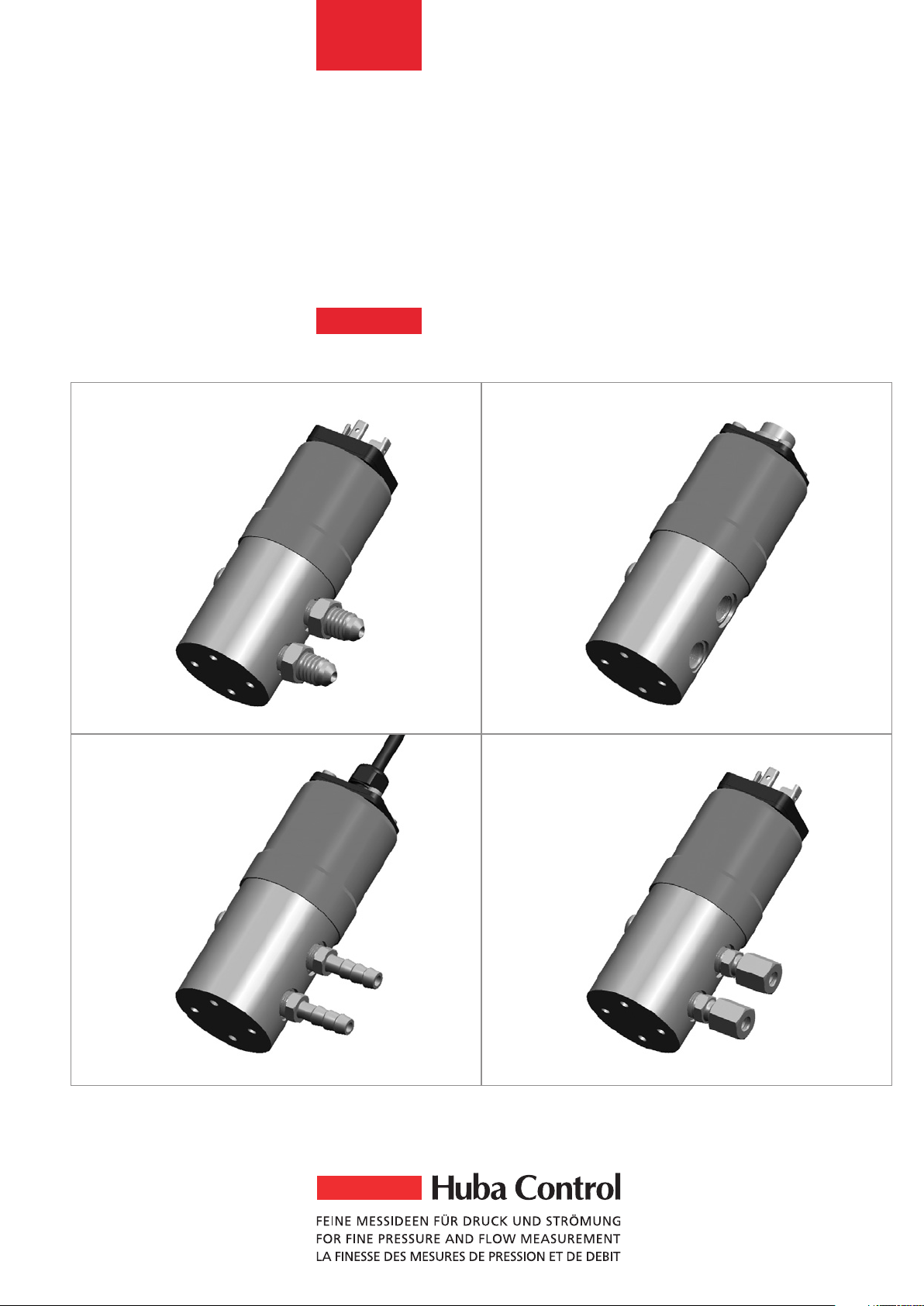
692
Differential pressure transmitter
0 … 0.1 – 25 bar
2
E
Technical overview
The differential pressure transmitter of type
series 692 with proven, unique ceramic
technology, features adjusted and amplified
sensor signals which are available as
standardised voltage or current outputs.
Various application-specific pressure and
electrical connections and housing materials
suitable for different media can be provided.
Medium
Liquids and neutral gases
Pressure ranges
0 … 0.1 – 25 bar
Tolerable overload on one side
See order code selection table
System pressure
25 bar on
differential pressure range <
6bar
50 bar on
differential pressure range >
10 bar
Rupture pressure
1.5 x system pressure
Setting range
(Only adjustable versions)
Zero point and full scale ±10% fs
Materials in contact with the medium
Pressure connection:
Stainless steel 1.4305 / AISI 303, PVDF,
CuZn vni
Diaphragm: Ceramic Al
2O3
(96%)
Sealing material: FPM, EPDM, NBR, MVQ
Case material
Stainless steel 1.4305 / AISI 303
Temperature
Medium and ambient –15 … +85 °C
Storage –40 … +85 °C
Output Power supply
3-wire
0 … 5 VDC 11 … 33 VDC
24 VAC ±15%
0 …10 VDC 18 … 33 VDC
24 VAC ±15%
2-wire
4 … 20 mA 11 … 33 VDC
Load
3-wire > 10 kOhm
2-wire <
[Ohm]
supply voltage – 11 V
0.02 A
Current consumption
At nominal pressure
3-wire < 5 mA
2-wire < 20 mA
Dynamic response
Suitable for static and dynamic measurements
Response time < 5 ms
Load cycle < 50 Hz
Electrical connection
Connector DIN EN 175301-803-A
Round connector DIN EN 60130-9
Cable 1.5 m
Polarity reversal protection
Short circuit proof and protected against
polarity reversal. Each connection is
protected against crossover up to max.
supply voltage.
Protection standard
IP 65
Pressure connections
Pressure-tube tip Ø 4 mm / 6 mm
Screw fitting Ø 6 mm / 8 mm
Outside thread 7/16-20 UNF, G1/8
Inside thread 1/8-27 NPT, G1/8
Installation arrangement
Unrestricted
Mounting
Mounting bracket
Tests / Admissions
CE conformity
Weight
Approx. 430 g
Packaging
Single packaging
in cardboard, accessories included
The distinct advantages
• Very low temperature sensitivity
• High resistance to extreme temperatures
• No mechanical creepage
• Modular system and choice of materials
to suit individual applications
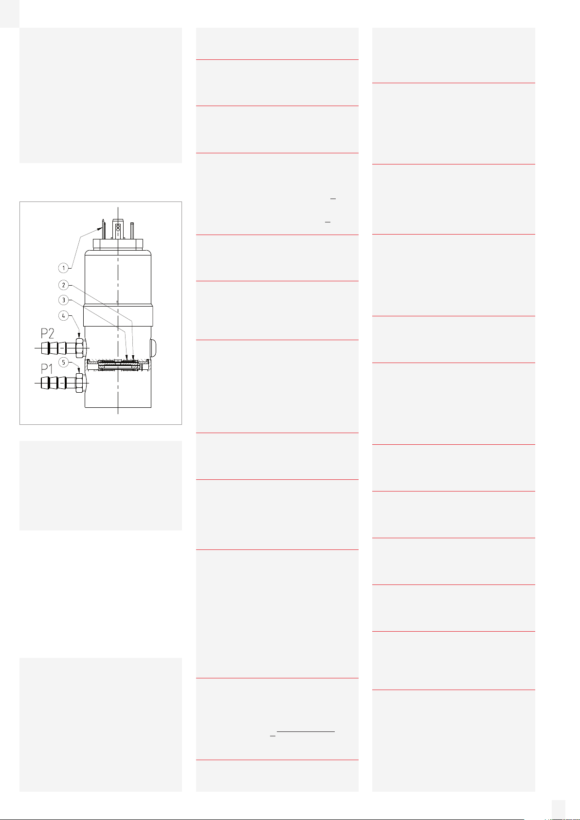
Legend to cross-section drawing
1 Electrical connection
2 Seals
3 Ceramic element
4 P2 Pressure connection (lower pressure)
5 P1 Pressure connection (higher pressure)
692 / EDITION 11/2007, Technical data subject to change.
 Loading...