

Huba 619 Service Manual
HUBA-REGISTERED TRADE MARK
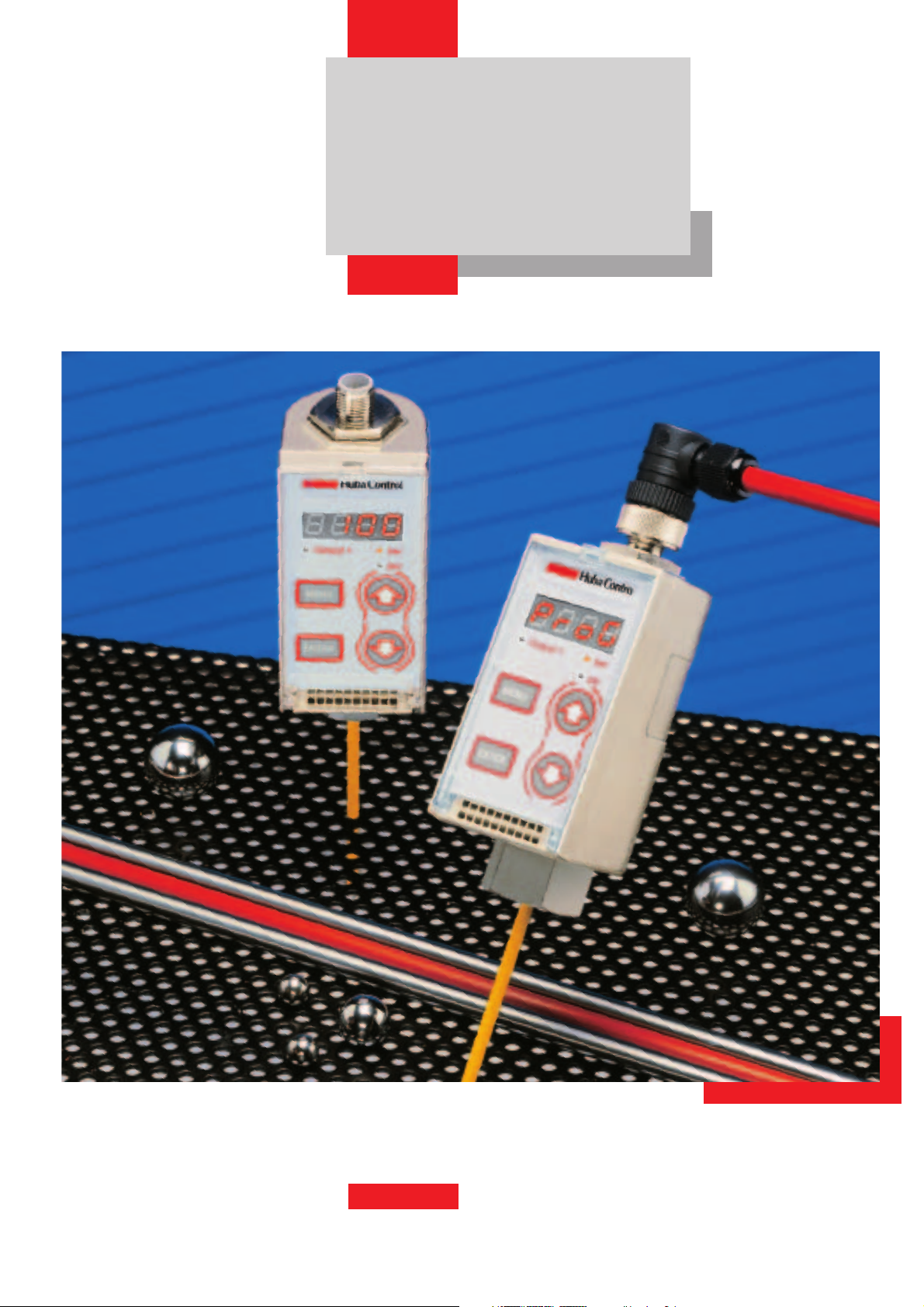
619
Pressure transmitter and
electronic pressure switch
programmable
Relative –1 to 600 bar
EDITION 02/2002
Huba Control
FOR FINE PRESSURE AND FLOW MEASUREMENT
Accuracy
Analogue output:
Total of linearity, hysteresis and
repeatability ≤ 0.6% fs
Zero point rest voltage < 200 mV
Digital output:
Accuracy of switching point
adjustments ≤ 0.6% fs
Housing material
Case: Nickel-plated Zinc pressure
die-casting
Key protection: PC with lettering
In contact with the media:
Ceramic / Stainless Steel (1.4305)
Sealing material: Viton
Temperature influences
Media and ambient
temperature –20 °C … + 80°C
TC zero point < 0.1% fs
TC sensitivity < 0.03% fs
Mechanical rating
Resistant to vibration
5 g (25 … 200 Hz)
35 g (60 … 2000 Hz)
according to IEC 68-2-6
Shock proof
50 g according to IEC 68-2-27
Pressure connection
Inside thread G 1/4
Weight
610 grams
Installation arrangement
Unrestricted
Protection class
IP 67
Power supply
17 … 33 VDC
Diagnostic function
Manual operation with keyboard:
Test of sensor circuit and of ceramic
cell as well as memorizing of pressure peak.
Version with diagnostic input
(shunt-cal): (feed-back with 50% fs
signal 12mA or 5 V
Technical overview
The µP-regulated, programmable
pressure transmitter type 619 has a
robust industry design. Parameters
can easily be programmed with
three different configuration menus.
All systems are equipped with a
diagnostic function. Pressure is
measured by a high resistante ceramic element. Normed analogueand / or open collector outputs are
available depending on the version
chosen.
Outputs
0 – 10 V
4 – 20 mA
Open-collector switching output for
max. 200 mA, programmable NPN
or PNP,
Contact NO or contact NC
Short circuit proof, and protected
against polarity reversal. Each
connection against other with max.
+/– supply voltage.
Load
0 – 10 V > 10 kOhm
4 – 20 mA < 500 Ohm
Current consumption
typ. 50 mA, max. 200 mA
Electrical connection
M 12, Snap-C compatible,
4 contact pins
Admission
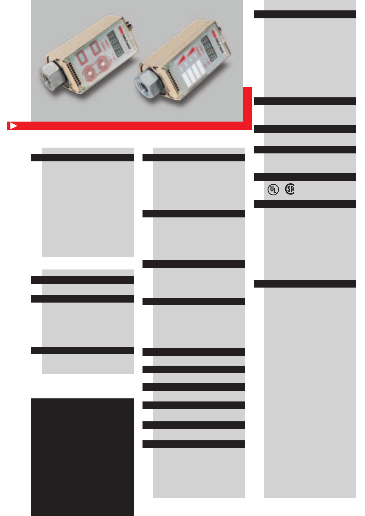
Displays
7 Segment LED, 4 digits for the
indication of
• pressure measuring values
• programming codes
• parameter values
• reaction time
Point-LED for state indication of
switching points
Point-LED for indication of programmed measuring unit
Programming
All settings can made in unpressurized state or during the operation.
Ex works with standard setting. The
diagnostic function is active in all
menus.
Menus: «PROG» Configuration of
different system functions, input of
switching point, diagnostic function
«USER» Input of switching point
«READ» Reading of all configurationand input parameters
Display: Pressure unit in bar/psi or
MPa/psi. Reaction time elegible in
steps 1% fs (slow), 0.5% fs (normal) or
10 ms (fast).
Analogue output: Response time
adjustable of 5 … 500 ms, output
characteristic line adjustable of
75 … 125% fs
Digital output: Measuring range
rising pressure 8 … 100% fs
falling pressure 5 … 97% fs
P or N-switching, open-closecontact, rise-delay time eligible
Rise-delay time 0 – 50 s
Switch off delay time 0 – 50 s
Response time 5 … 500 ms
The distinct advantages
• Robust industry design
• High over pressure
• 4-digit LED display
• Sensitive operation keys
• Ergonomic design
• Diagnostic function
• Front cover
EDITION 02/2002
Kind of pressure
Relative pressure
Overload
–1 … 250 bar
4 x measuring range full scale (fs)
–1 … 400 bar
3 x measuring range full scale (fs)
–1 … 600 bar
2 x measuring range full scale (fs)
Rupture pressure
6 x measuring range full scale (fs),
max. 1800 bar
 Loading...