

Huayi MS2205 Instruction Manual

I
Contents
Safety Requirements .............................................................................................. 1
Safety Instructions .................................................................................................. 1
Safety Sign ............................................................................................................... 2
General Description ................................................................................................ 2
Features ................................................................................................................... 2
Appearance .............................................................................................................. 3
Knob Switch Operations ......................................................................................... 4
Button Switch Operations ...................................................................................... 5
LCD Display .............................................................................................................. 8
Instruction Manual .................................................................................................. 9
Test Data Storage ................................................................................................. 17
Read Saved Data .................................................................................................. 17
RS232C Data Interface ........................................................................................ 18
Input Voltage and Current ................................................................................... 19
Backlight Display ................................................................................................... 19
Auto Power Off ...................................................................................................... 19
Diagram of Safe Holding ...................................................................................... 20
Power curve diagram ........................................................................................... 20
Battery-low Indication .......................................................................................... 22
Battery Replacement ............................................................................................ 22
General specification ............................................................................................ 23
Technical specification ......................................................................................... 23
Accessories ............................................................................................................ 26

1
Safety Requirements
Please carefully read the instruction manual before using the tester, and pay special
attention to “Warning” content. Please follow instructions under “Warning”.
1. Please be very careful when test voltage is higher than AC 30 V, and do keep
in mind that your finger shall not exceed the hand-shielding part of the test
probe.
2. Do not measure voltage which is higher than the allowed input limit.
3. Before use, please check the meter and test probe; do not carry out testing in
case the test probe is naked, tester housing is damaged, or there is no LCD
display, etc..
4. It meets requirements of safety standards only when the meter is used together
with the supplied test probes. In case the test probe is damaged and needs
replacement, it is required to replace it with a test probe of the same model
and identical electrical specifications.
5. Please never carry out any voltage measurement whenever the test probe is
inserted in any current outlet.
6. Please do not expose the meter to strong light, high temperature, or dampness.
Before use, please carefully read this instruction manual.
Especially safety contents!
Safety Instructions
The three-phase clamp-type digital power meter is designed and manufactured in
accordance with international standard, IEC61010-1, and international safety
specification, IEC1010-2-032, and the meter strictly follows the safety standard of
double-insulation AC 600 V CAT III.
Warning
2
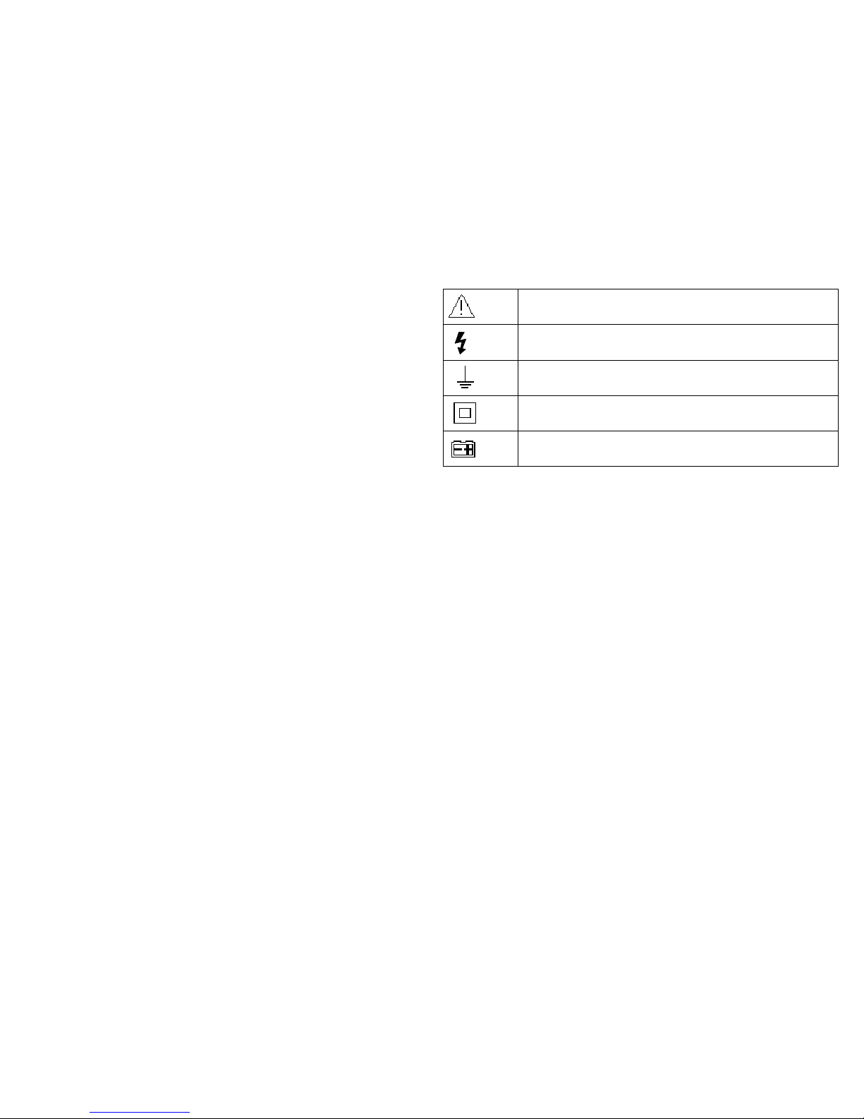
Safety Sign
Important safety signs; please refer to instruction manual
High voltage hazard
Earthing
Double insulation (Category-II safety equipment)
Battery low Indicator
General Description
The 3-phase clamp-type digital power meter is a hand-held intelligent harmonic
power tester, with both functions of digital current testing and power testing. The
tester is comprised of three channels including voltage, current, and power as well
as a micro single chip system, and it is equipped with a powerful software for
measurement and data processing functions; it can measure, calculate, and display
voltage, current, active power, power factor, apparent power, passive power,
frequency, harmonic parameters, with stable performance and operation
convenience. The meter is especially suitable for the measurement and examination
of on-site power equipment and power-supplying circuits; with hand-held clamp
structure, small volume, and light weight, it can be easily carried by the user, which
makes it easy and fast for doing measurement. For measurement of
sing-phase/three-phase power, The meter is your ideal choice.
Features
1. The meter can be used for testing power, voltage, current, peak value, phase,
frequency, power factor, phase angle, and reaction factor, etc. of
single-/three-phase circuit; automatic phase sequence testing is possible for
3-phase measurement.
2. True effective value measurement: accurate measurement is possible even
3
with serious distortion in current waveform.
3. Low-consumption high-speed single-chip microprocessor is employed and
sophisticated algorithm is applied, as a result, results can be obtained rapidly
and precisely, and up to 20 harmonics and distortion value thereof can be
measured.
4. It is equipped with a large-size memory for saving up to 100 groups of test
parameters.
5. It is equipped with RS232C communication and recording interface and
dedicated WINDOWS graphics software.
6. Hand-held, clamp-type structure, with light weight, convenient for carry-on.
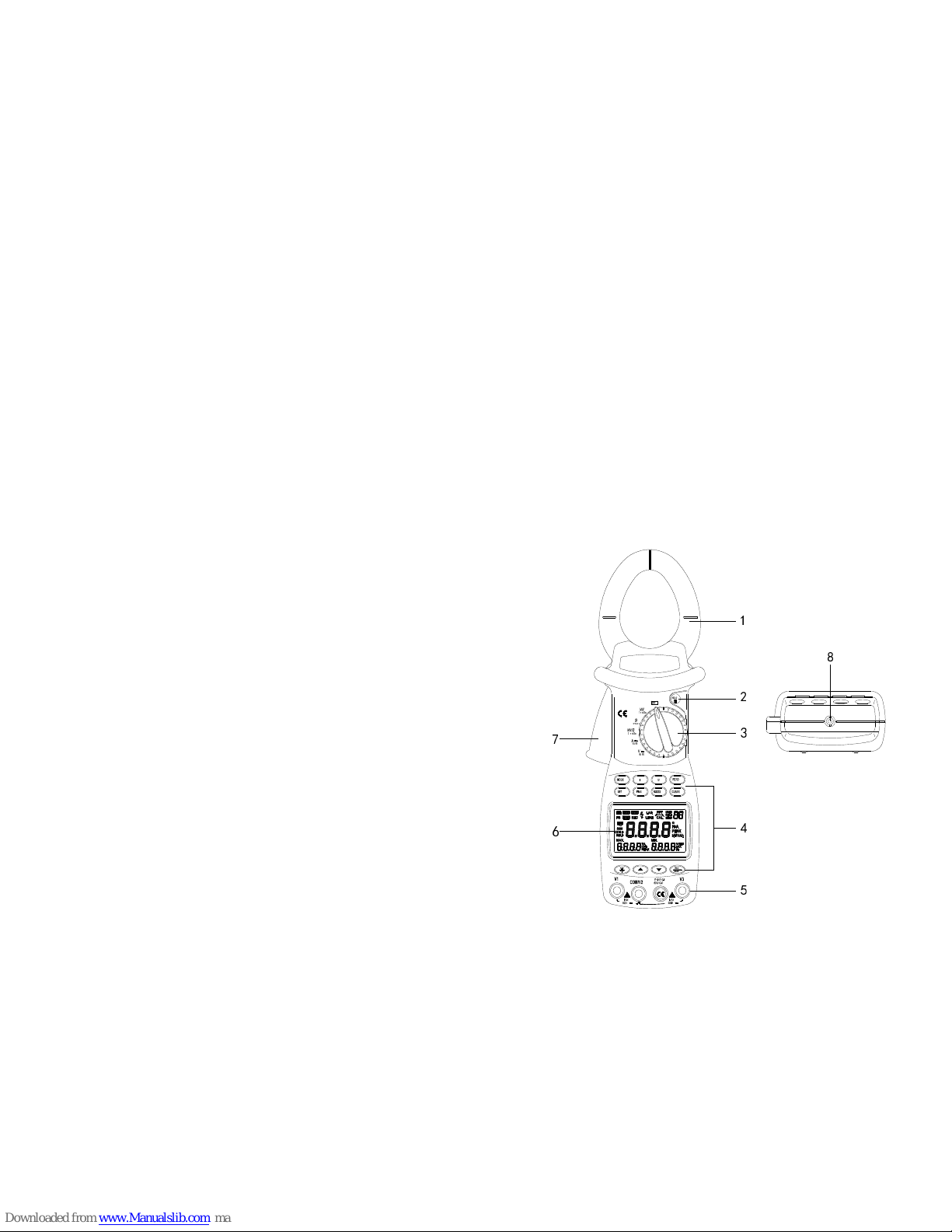
Appearance
3 PHASE
1PHASE
1PHASE
HARM
HARM
1
2
3
4
5
6
7
8
4
1. Current clamp size: Φ 50 mm
2. HOLD button :DATA HOLD button; press down HOLD button, and the last
reading will be held and displayed on the display, and “HOLD” symbol will
be shown; press HOLD button again, and the meter will switch back to
normal measurement mode.
3. Function-switching knob :Rotation knob for selecting different measuring
function
4. Function-selection button: Button for operating the measuring functions
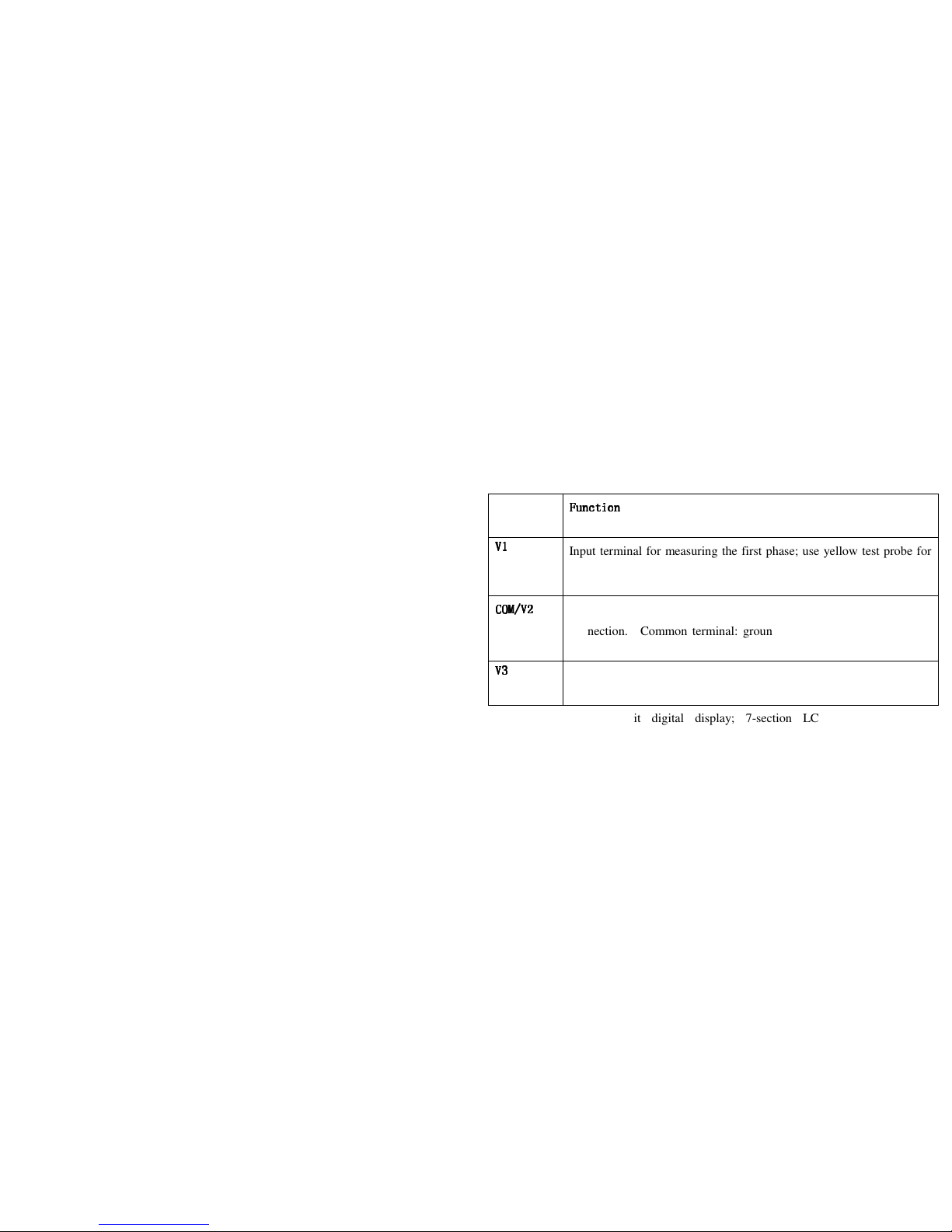
5. Input terminal
Terminal
Function
FunctionFunction
Function
V1
V1V1
V1
Input terminal for measuring the first phase; use yellow test probe for
connection.
COM/V2
COM/V2COM/V2
COM/V2
Input terminal for measuring the 2nd phase; use black test probe for
connection. Common terminal: ground input terminal (earthing) for
all measuring functions; use black test probe for connection.
V3
V3V3
V3
Input terminal for measuring the 3rd phase; use green test probe for
connection.
6. LCD display :4-digit digital display; 7-section LCD for displaying
measurement operation function, test result, and unit sign.
7. Trigger :Press down the trigger, and the clamp will open; release it, and the
clamp will close.
8. RS232C interface: Dedicated optical-electrical interface wire is used for
online communication with PC, as well as for recording data and data trend
curve in PC.
Knob Switch Operations
The function-switching knob is used for powering-on and for switching to any
measurement function in the following table.
5
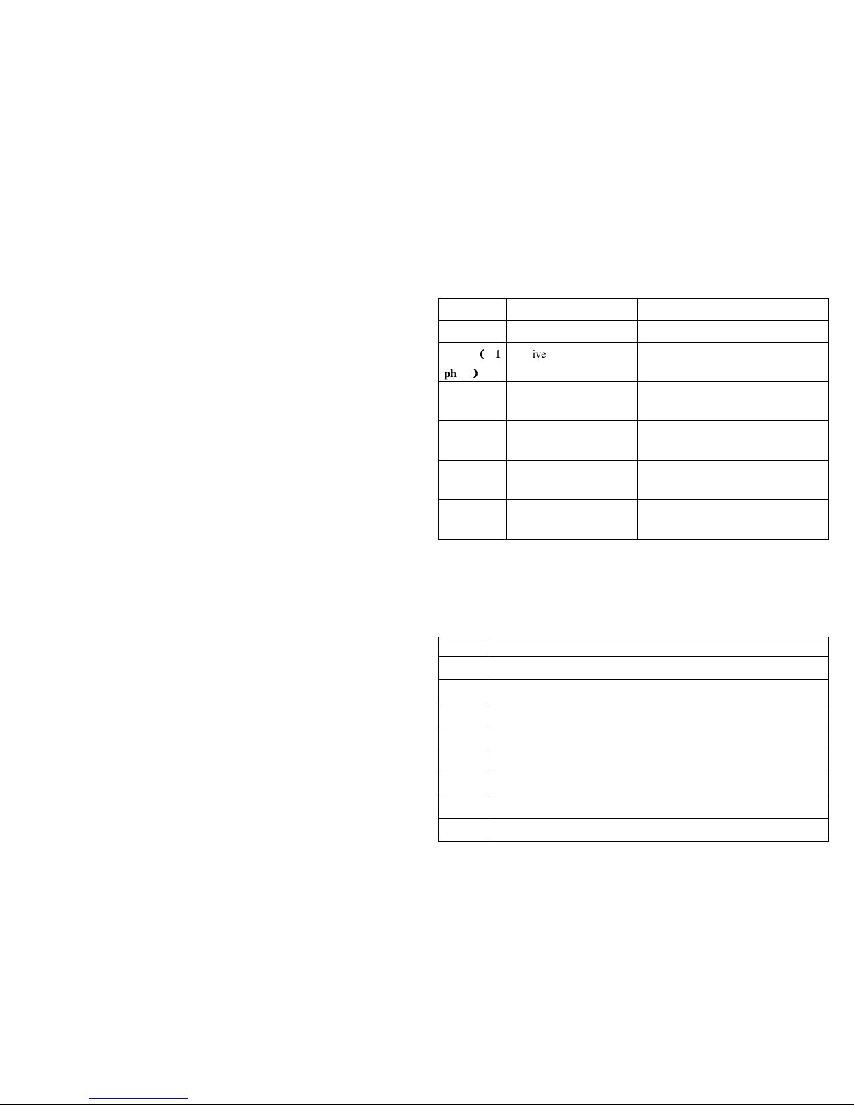
Knob position description
Sign
Knob position
Functions
OFF Powering-off position For powering-off
KW
((((
1
phase
))))
Active power position For measuring active power, etc.
Φ (1 phase) Single-phase/phase-angle
Test position
For measuring phase angle, such as cos
Φ and sin Φ, etc.
KW/Φ(3
phase)
3-phase apparent power
position
For measuring 3-phase apparent pow
er, etc.
A ~ AC-current harmonics te
st position
For measuring AC-current harmonics
, etc.
V ~ AC-voltage harmonics te
st position
For measuring AC-voltage harmonic
s, etc.
Note:
When the meter is automatically powered off, be sure to switch the knob to
“OFF” position; turn on the meter after 5 seconds.
Button Switch Operations
Button descriptions
SN
Function-selection button
1 MODE Test-mode switching button
2 SET SET button
3 I Current test button
4 WATT Power test switching button
5 U Voltage test button
6 READ Data-Reading button
7 RS232 RS232C button
8 CLEAR Clear memory button
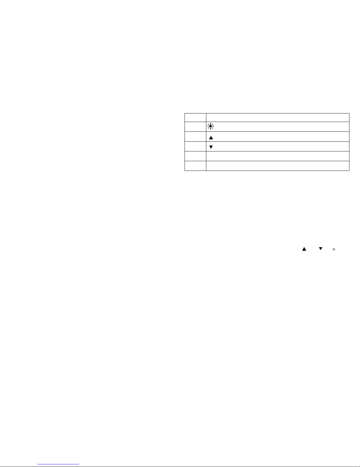
6
SN
Function-selection button
9 Backlight button
10
▲
Reverse-search button
11
▼
Forward-search button
12 REC/SAVE Data recording & storage button
13 HOLD Hold button
The following functions can be realized through button operations:
WATT Button
Under test mode, you can measure active power, apparent power, power factor, and
phase angle and display the results on LCD by pressing WATT button.
MODE Button
Under KW-test mode, you can press MODE button to switch the display of active
power and passive power; under A/V~ test mode, you can switch the display
among total harmonic distortion rate F, r, and harmonic percentage.
SET Button
Under test mode, you can press SET button and then press ▲ and ▼ button to
set the range of current and voltage, and then press this button again to return. This
button serves as CONFIRMATION button during storage and deleting.
U Button
Under test mode, you can press this button to test voltage of the present circuit, and
display the measured voltage of the present circuit on display.
READ Button
Under HOLD mode, you can press this button to display the stored data; press this
button again to return.
I Button
Under test mode, you can press I button to measure current of the present circuit
and display the measured current of the circuit by the clamp on LCD.
RS232 Button

7
Under test mode, you can press RS232 button to transfer the present test result to
PC through a dedicated interface wire supplied for the meter so as to record/print
data and data trend graph.
Before pressing RS232 button for data transferring, the supplied RS232C interface
wire shall be connected to RS232C interface socket of the meter and PC COM port,
before realizing communication functions.
CLEAR Button
Under data-reading mode, you can press CLEAR button and then press SET
button to clear the test data which is stored in the meter under a specified number.
Button
You can press button to turn on or off the backlight. After it is turned on for 20
seconds, the backlight will automatically be turned off.
▲
Button
Under VOLTAGE-RANGE-SETUP mode, you can press ▲ button to change
the voltage test range. During testing harmonics, you can change the times
of harmonics.
When reading the saved data, you can press ▲ button to search backward t
hestored data and show it on LCD. With every press of the button, the sear
chingcursor will move one step backward to the previous data.
▼
Button
Under CURRENT-RANGE-SETUP mode, you can press ▲ button to change
current test range. During testing harmonics, you can change the times of
harmonics.
When reading the saved data, you can press ▼ button to search in the forward
direction the stored data and show it on LCD. With every press of the button, the
searching cursor will move one step forward to the next data.
REC/SAVE Button
Under TEST mode, you can press REC/SAVE button to display the max. /min.
power, current, voltage that is currently measured; under DATA HOLD mode,
press this button to display the stored number; press SET button again to save the
8
held data in the meter. Up to 100 groups of data can be stored in the meter.
HOLD Button
After measurement, press this button to hold this data on LCD; after powering-off,
data will display.
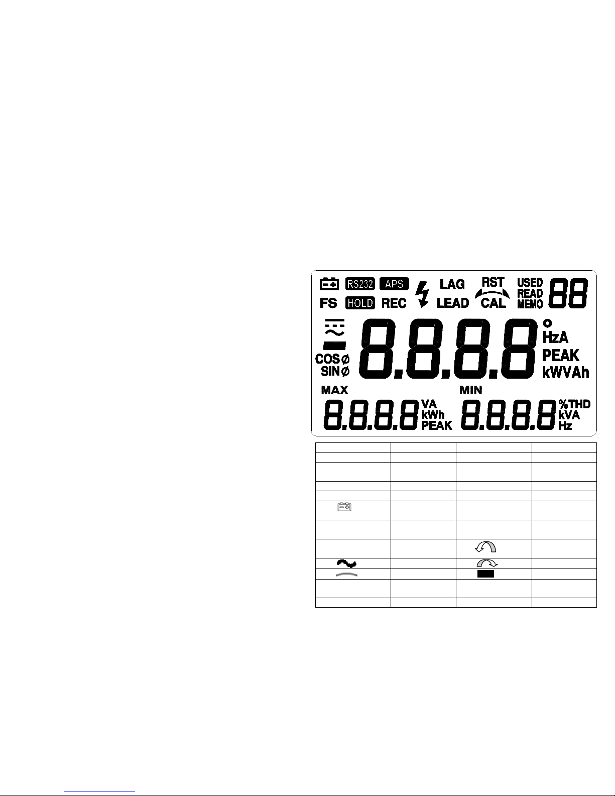
LCD Display
LCD symbol
Description
LCD symbol
Description
RS232
Data transfer
REC
Data recording
APS
Auto
powering-off
F
Fast
HOLD
Data holding
S
Slow
LAG
Phase angle lag
LEAD
Phase angle lead
Battery power
indication
o
Phase angle
(degree)
SINΦ
Reversed power
factor
COSΦ
Power factor
RST
3-phase
Normal phase
AC symbol Reversed phase
Phase lacking
Negative symbol
MIN
Minimum value
MAX
Maximum value
USED
Used
MEMO
Save
 Loading...