

Huayi H782 Instructions Manual

H782
ProcessMultimeter
Instruction

Shenzhen Huayi Instrument Technology Co., Ltd.
H782 ProcessMultimeter
Content
Content
1.
Safety Information
……………………………….……1
1.1
Preparation
…………………………….………1
1.2
Use
…….………………………………2
1.3
Marks
………………………………….…3
1.4
Maintenance
……………………………….……4
2.
Description
…………………………….………6
2.1
Parts name and relevant
description
………………………………….…..8
2.2
Display
……………………………...……10
3.
Specification
……………………………...……12
3.1
Summary
……………………………...……12
3.2
Technical index
……………………………...……13
4.
Operation guidance
……………. ……………….……20

4.1
Power charging
……………………………...……20
4.2
Auto power off
…………………………………...21
4.3
Backlight
…………………………………...21
4.4
Reading hold
…………………………………...22
4.5
Function switch
…………………………………...22
4.6
Relative measurement
switch
…………………………………...23
4.7
Measurement preparation
…………………………………...24
4.8
DC voltage measurement
…………………………………...25
4.9
AC voltage measurement
…………………………………...26
H782 ProcessMultimeter
Content
4.10
DC current measurement
………………………………….…28
4.11
AC current measurement
………………………………….…29
4.12
Resistance measurement
……………………………….……30
4.13
Capacitance measurement
…………………………….………31
4.14
Diode test
……………………………….……32
4.15
Circuit break-and-make
test
……………………………….……32
4.16
Frequency measurement
……………………………….……33
4.17
Triode magnification times
measurement
…………………………….………34
4.18
Temperature
measurement (sensor:
thermocouple)
……………………………….……34

4.19
Battery voltage
measurement
……………………………….……35
4.20
Current output
……………………………….……36
4.21
Voltage output
…………………………….………37
4.22
Frequency output
…………………………….………39
4.23
24VDC output
………………………….…………41
5.
Maintenance
…………………………….………41
5.1
Replace the battery pack
…………………………….………41
5.2
Replace the protective
tube
…………………………….………42
5.3
Replace the test lead
……………………………….……43
6.
Accessories
……………………………….……44
H782 ProcessMultimeter
Safety information
1. Safety information
warning
Please pay special attention when using
this instrument, improper use may cause
electric shock or damage to it. It shall
conform to common safety rules and
completely follow the safety measures
regulated in this instruction.
To make the best of the functions of this
instrument and ensure safe operation, please

carefully read and follow the use method in
this instruction.
H782 ProcessMultimeter (hereafter, also referred to as ―the
instrument‖) complies with GB/T 13978-92 common technical
specifications for digital multimeter and meets GB4793.1-1995
(IEC-1010-1: 1990) safety requirements for electronic measuring
instrument which subjects to Pollution Grade 2 and Overvoltage
Criterion CAT II 1000V/CAT III 600V.
Please follow the safety operation guidance to ensure safe use of
this instrument.
This instrument may serves you well if use and protect it
appropriately.
1.1 Preparation
1.1.1 The user must follow standard safety regulations:
1) Normal protection against electric shock
2) Prevent misuse of the instrument
H782 PrxocessMultimeter
`
Safety information
1.1.2 Check if there is any damage results from transportation after
receiving this instrument.
1.1.3 Check and confirm if there is any damage after keeping or
transporting the instrument in harsh conditions.
1.1.4 The test leads must be in good condition. Check the test leads for
insulativity damage and check the lead wire for exposed metal.

1.1.5 It shall use the test leads attached with the meter to ensure
safety. Otherwise if necessary, it must use the same test leads
or the one with the same grade.
1.2 Use
1.2.1 It must use the proper input/output jack, function and range.
1.2.2 Do not conduct measurement or output out of the indicated value
of protection scope within each range.
1.2.3 Do not contact the tip of test lead (metal part) when connecting
the instrument to a circuit under measured.
1.2.4 When measuring, if the measured voltage is higher than 60V DC
or 30V AC (virtual value), please be noted to keep fingers behind
the finger guard on the probe.
1.2.5 Never measure the voltage higher than 1000V between the
measuring terminal and the earth.
1.2.6 If in range of current, resistance, capacitance, diode,
break-and-make, temperature, triode or amplification times
H782 PrxocessMultimeter
`
Safety information
test, cares shall be taken to avoid connecting the instrument to
the voltage source
1.2.7 Before turning the rotary switch to change measuring function, it
shall remove the test lead from the circuit-under-test.
1.2.8 When measuring the switch power circuit, the high-voltage pulse
on the test point may damage the instrument.

1.2.9 Do not measure the resistance, capacitance, diode and/or
break-and-make that is live.
1.2.10 Do not measure the capacitance before the capacitor is
completely discharged.
1.2.11 Never use this instrument near explosive gas, vapor or dust.
1.2.12 If any abnormality or failure found on the instrument, please be
sure stop using.
1.2.13 Do not use this instrument unless the bottom case is completely
fastened.
1.2.14 Do not store or use this instrument in environment with direct
sunshine, high temperature and high humidity.
1.3 Marks
Important safety information, please refer to the instruction.
There may be dangerous voltage.
Dual insulation protection (Category II)
CAT The level of pulse withstand voltage provided according to
overvoltage (installation) Grade , Pollution Degree 2
H782 PrxocessMeter
`
Safety information
of IEC-1010-1.
CAT The level of pulse withstand voltage provided according to
overvoltage (installation) Grade , Pollution Degree 2 of
IEC-1010-1
Conform to European Union (EU) directives

Earth ground
Protective tube
Low battery power
1.4 Maintenance
1.4.1 Please do not attempt to open the bottom case to adjust or repair
the instrument, which should only be carried out by the
technician who knows the instrument and electric shock risk
well.
1.4.2 Before open the battery cover, the test lead shall be removed
from the measured circuit.
1.4.3 Once the symbol
appears, please charge the instrument with
the attached charger immediately to avoid reading error which
may cause electric shock.
1.4.4 To avoid combustion, the replacing protective tube must meet
specified voltage and current class: F 0.5A/250V (quick fusing)
1.4.5 It shall clean the instrument with wet cloth and detergent, never
use abrasive or solvent.
1.4.6 Rotate the rotary switch to OFF when the instrument is not in
use.
1.4.7 It shall charge the instrument regularly or remove the battery if
it will be not in use for long, in order to avoid damage.
H782 PrxocessMeter
`
Safety information
2. Description

This meter is a portable and specialized process verification
instrument, which presents as a digital verification meter that has
both digital multimeter and signal source function, and can measure
and output signal simultaneously. Its large liquid crystal digital
display can show and measure the output signal value at the same
time, and it is equipped with backlight which makes the user easier
to read the value. It uses large-capacity rechargeable battery pack
and is featured with low voltage indication. Charging and operating
for this instrument can be conducted simultaneously (with a charger).
Signal output and measurement function of the instrument is mainly
designed for on-site verification and service of an instrument in
industrial automation field. This instrument is also featured with
multimeter function, which makes it an ideal option for field
meterman, computer distributed control system maintainer, meter
mounter, and can be used as a multimeter by the meterman.
- It delivers 24V DC voltage output (I
max
=30mA), which may be used
to supply operating source to two-wire system meter.
- Current output.
- mV output.
- Frequency output.
- Voltage output.
- The process verification multimeter is used for DC voltage, AC
voltage, DC current, AC current, resistance, capacitance, frequency,
temperature and break-and-make, diode and triode test.
- When using, the instrument displays the measured value and its unit
symbol.
- The instrument is featured with range auto-switch, reading hold and
relative measurement.
H782 ProcessMultimeter
Description
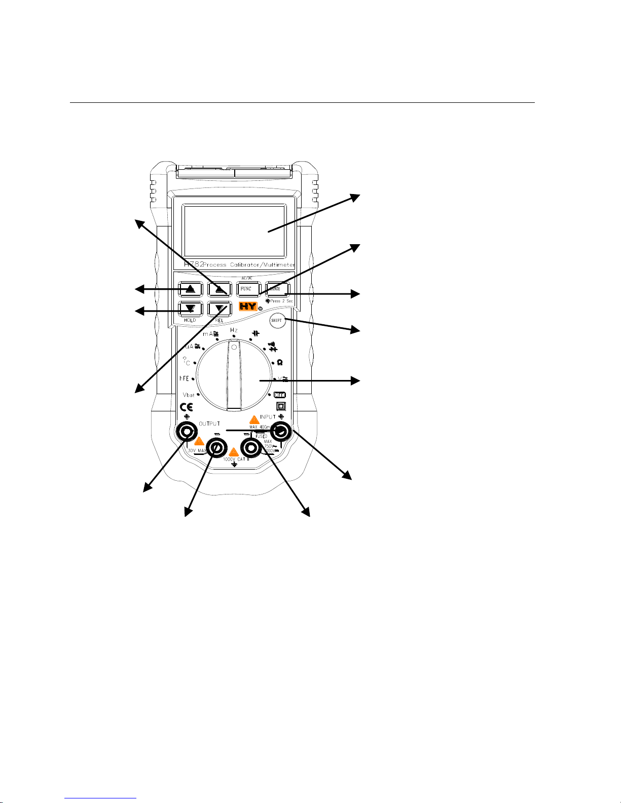
2.1 Parts names and relevant descriptions
1 2 3 4 5 6 7
8
9
10
13
12
11
H782 ProcessMultimeter
Description
1) LCD (Liquid crystal display): displays the measured reading and
see the magnitude of output signal.
2) ▲Key: to control the output signal to a low increasing speed.
3) ▲Key: to control the output signal to a high increasing speed.
4) ▼/HOLD Key: to control the output signal to a high reducing speed
(output display area) or to hold the measured
reading (measurement display area)
5) ▼/REL Key: to control the output signal to low reducing speed
(output display area) or to read the relative
measurement (measurement display area)
6) FUNC Key: to switch among output voltage (output display area),
current, frequency, or to switch input signal types
(measurement display area).
7) RANGE Key: to switch the range of output signal and turn on/off
the backlight.
8) SHIFT Key: to determine whether the key for output or
measurement.
9) Rotary switch: to select output measurement function and power
switch.
14
15
H782 ProcessMultimeter
Description
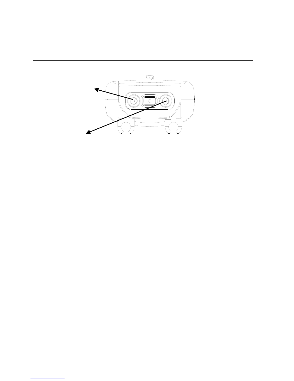
10)INPUT + jack: positive terminal of connection for voltage, current,
resistance, frequency, temperature, capacitance,
diode, triode, break-and-make position input.
11)INPUT — Jack: common terminal for measurement.
12)OUTPUT — Jack: negative terminal for output signal.
13)OUTPUT + Jack: positive terminal for output signal
14)Charge Terminal
15)24VDC Output Terminal
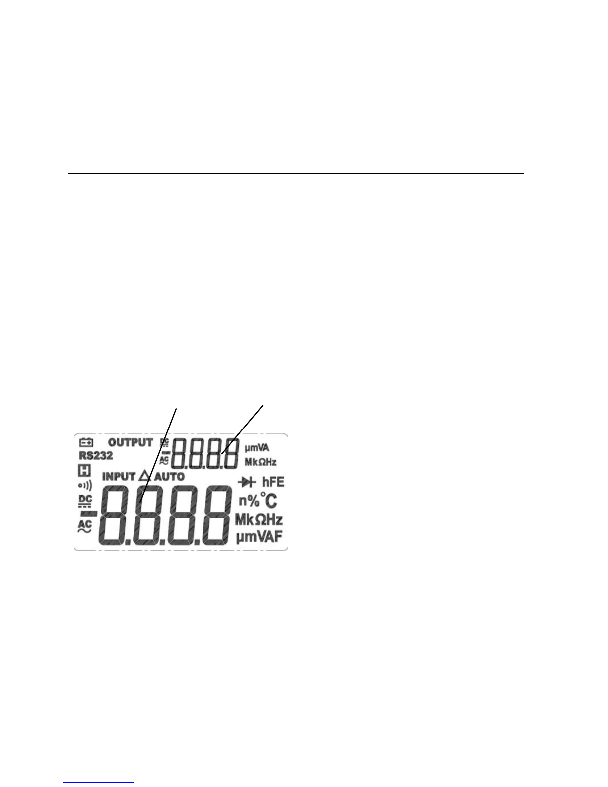
2.2 Display
① ②
H782 ProcessMultimeter
Description
1) ①Measurement display area
2) ②Output display area
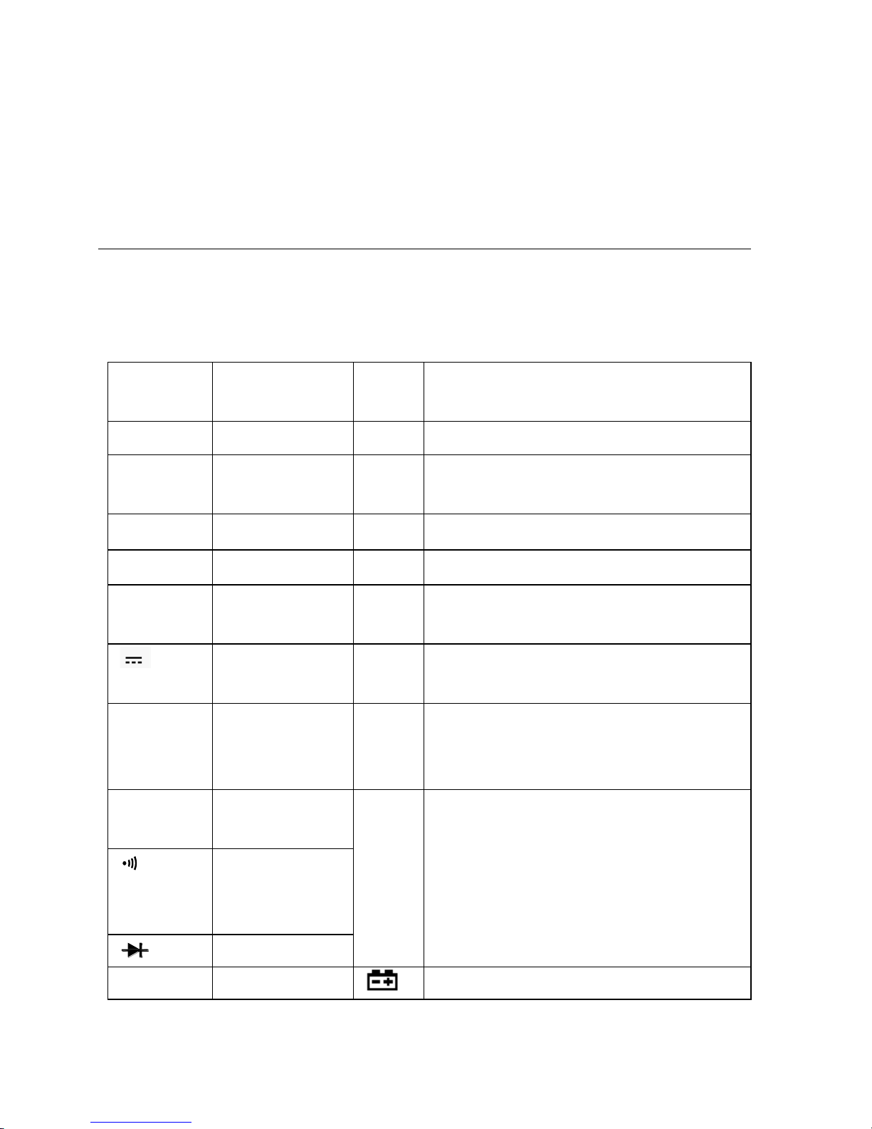
Symbol
Description
Sym
bol
Description
INPUT
Input signal
℃
Centigrade (temperature)
OUTPU
T
Output
signal
F
Farad (Capacitance)
RS232
Reserve
Ω
Ohm (resistance)
AUTO
Auto range
V
Volt (voltage)
~ AC
Alternating
current
A
Ampere (current)
DC
Direct
current
Hz
Hertz (frequency)
Δ
Relative
measuremen
t
%
Duty cycle (square wave)
H
Reading
hold
n、μ
m、k
M
Unit symbol: nano, micro, milli,
kilo, million
Buzzing for
break-andmake test
Diode test
hFE
Triode test
Low battery power

H782 ProcessMultimeter
Specification
3. Specification
It shall define one year as the calibration period of the
instrument, which shall be taken place in environment with
temperature 18℃ ~ 28℃ and relative humidity 75%.
3.1 Summary
3.1.1 30V overload protection for two output terminals.
3.1.2 Auto range.
3.1.3 Overload protection within full range.
3.1.4 The max allowable voltage between the measuring terminal and
the earth: 1000V DC or AC (virtual value)
3.1.5 Operation elevation: max 2000m
3.1.6 Display: LCD, which can show output and measured data
simultaneously.
3.1.7 Max displayed value: 3999 number.
3.1.8 Polarity indication: auto indicating, ‗-‘ refers to the negative
polarity.
3.1.9 Outrange indication: ‗OL‘ or ‘-OL.‘
3.1.10 Sampling frequency: about 0.4sec/time.
3.1.11 Unit display: display function and electric quantity unit.
3.1.12 Time for auto power off: 15 minutes.
3.1.13 Self-recovery fuse specification: 500mA/250V.
3.1.14 Operating source: 1.2V×4 AA battery pack with
 Loading...